
1963 Chevy Nova LS6 Swap


 04-12-2012, 04:50 PM
#82
On The Tree
Thread Starter
Join Date: Sep 2010
Location: San Luis Obispo CA
Posts: 155
Likes: 0
Received 0 Likes
on
0 Posts

 04-25-2012, 01:47 PM
#84
11 Second Club
iTrader: (4)
Join Date: May 2007
Location: Chicagoland
Posts: 342
Likes: 0
Received 0 Likes
on
0 Posts
Ok, I am working on a trade for a 63 nova at the moment, and IF it goes through, I am all over putting a new power plant in it. Unfortunately my funds are limited to next to zero so my build will be completed maybe when I retire...
04-26-2012, 09:51 PM
#85
On The Tree
Thread Starter
Join Date: Sep 2010
Location: San Luis Obispo CA
Posts: 155
Likes: 0
Received 0 Likes
on
0 Posts
 Hopefully your deal goes through!
Mine is taking a while too, but I will get it done!! I think I'll tackle the driveshaft this weekend.
06-18-2012, 09:19 PM
#86
On The Tree
Thread Starter
Join Date: Sep 2010
Location: San Luis Obispo CA
Posts: 155
Likes: 0
Received 0 Likes
on
0 Posts
June 9, 2012 (Do the dates even matter anymore?)
Slowly progressing, but not dead... Looks like my goal of having this thing finished by the end of summer is looking pretty good.
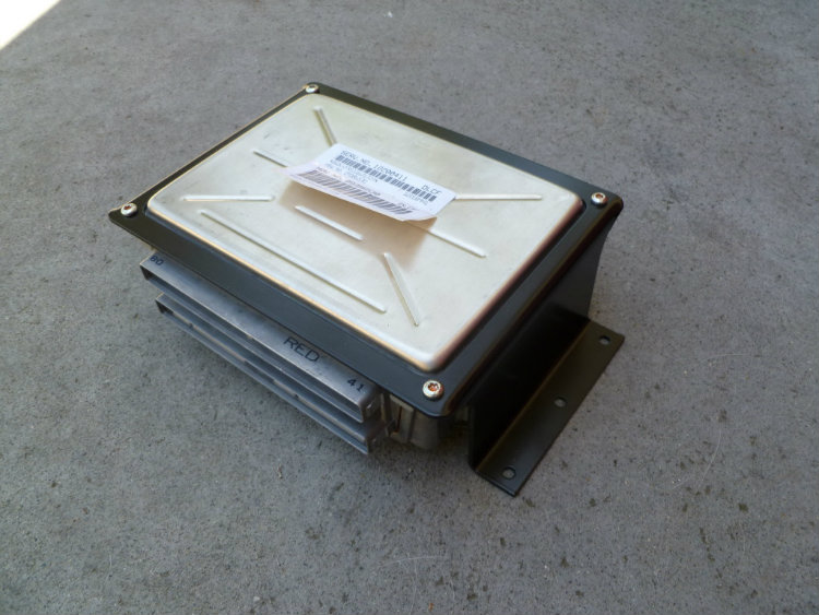
I ordered up an ECM/PCM bracket and had it powder coated. I'll be mounting this under the passenger side seat. Looks pretty good.
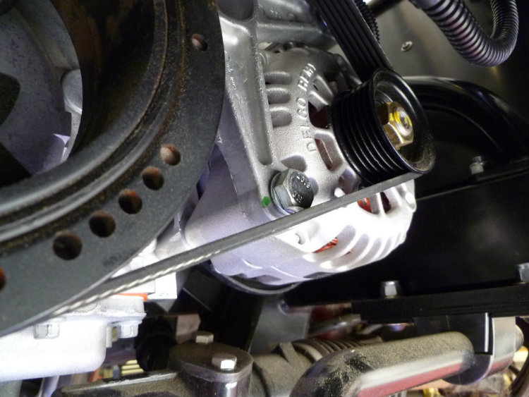
Over the last month, I've just been taking care of little things like the overflow tank, plug wires, etc. (and this little problem below). The belt makes contact with the alternator bolt so I've decided to look for an ARP bolt with the smaller head or replace it with a button head bolt. I didn't really want to buy a larger pulley.
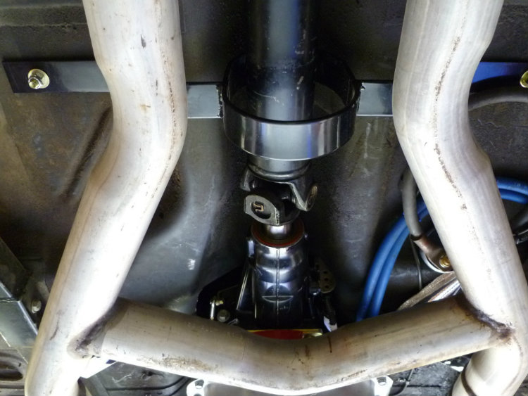
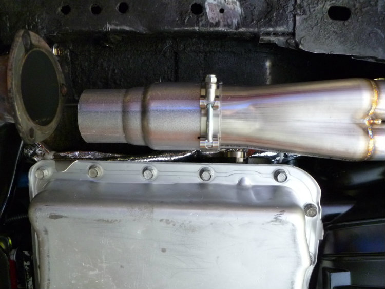
Driveshaft cut down and installed:
Looking to get the exhaust taken care of pretty soon...
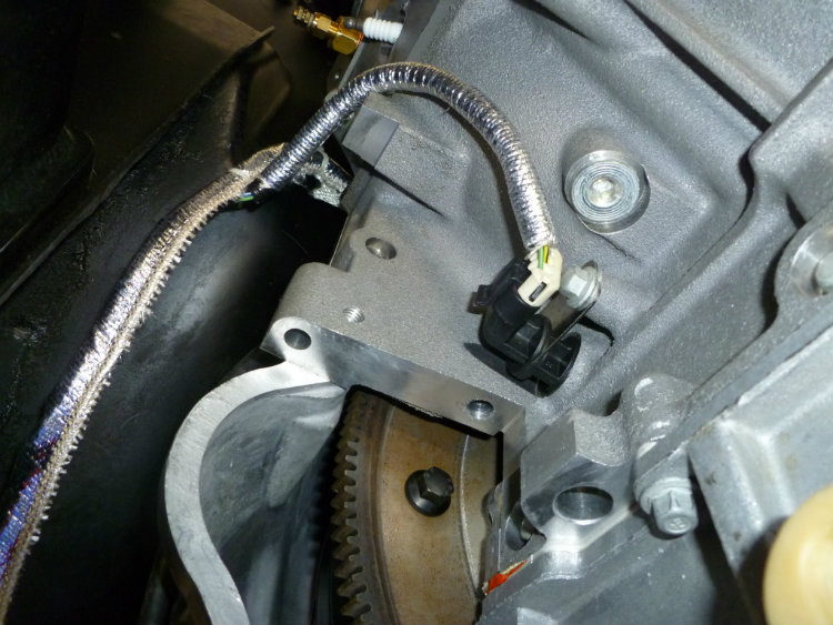
And now for my least favorite part, the wiring.
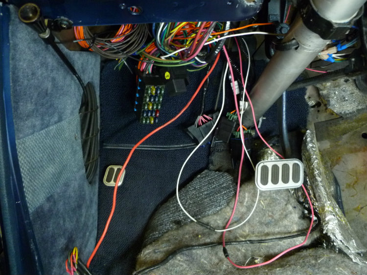
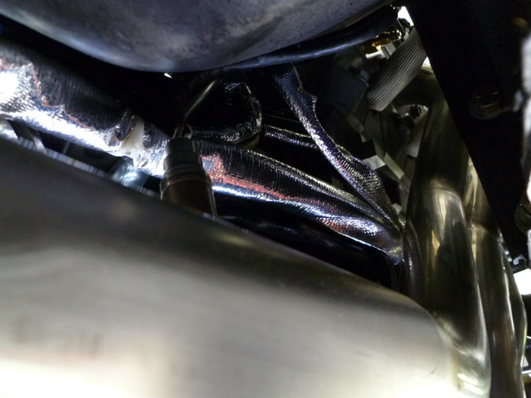
Apparently, you have to take out the header and starter to plug the crank sensor in. I know that now ... bastard sensor
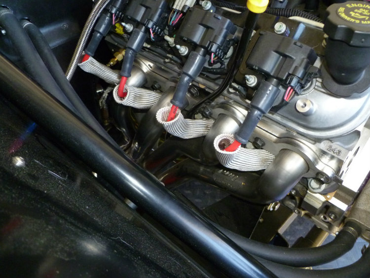
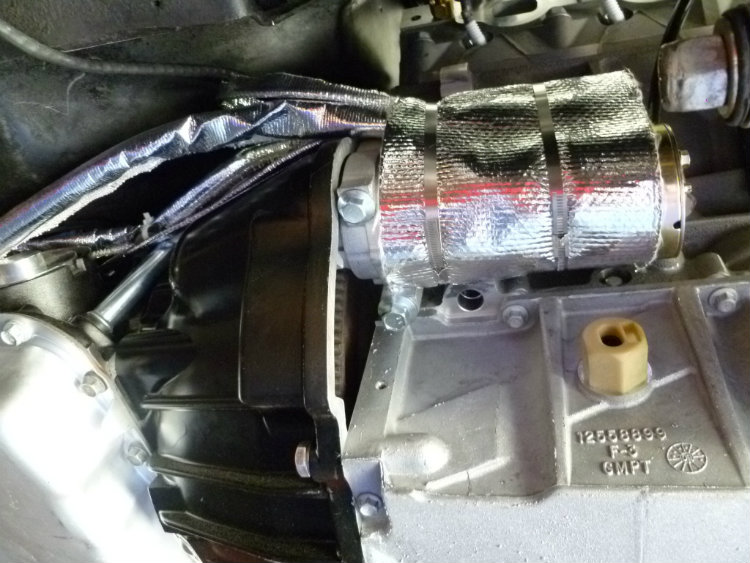
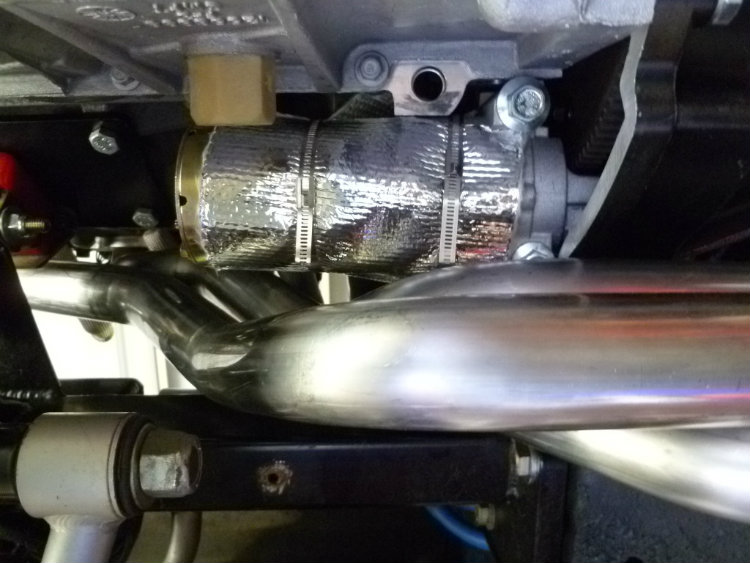
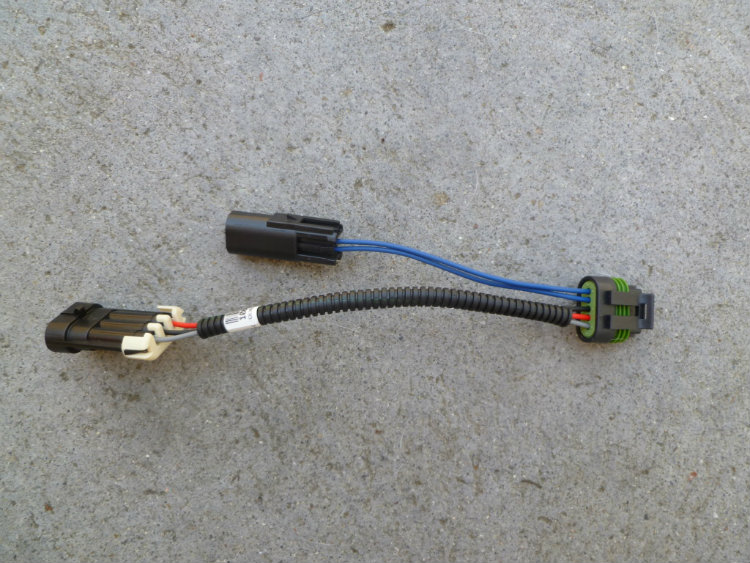
When I ordered my wiring harness, I neglected to tell the company I was using a five pin MAF (which combines the MAF and IAT sensors). I didn't realize this until I started plugging in everything, so I had to get an adapter to convert the 3 pin MAF and IAT sensor to the 5 pin MAF shown below.
Slowly progressing, but not dead...
Looks like my goal of having this thing finished by the end of summer is looking pretty good.I ordered up an ECM/PCM bracket and had it powder coated. I'll be mounting this under the passenger side seat. Looks pretty good.
Over the last month, I've just been taking care of little things like the overflow tank, plug wires, etc. (and this little problem below). The belt makes contact with the alternator bolt so I've decided to look for an ARP bolt with the smaller head or replace it with a button head bolt. I didn't really want to buy a larger pulley.
Driveshaft cut down and installed:
Looking to get the exhaust taken care of pretty soon...
And now for my least favorite part, the wiring.
Apparently, you have to take out the header and starter to plug the crank sensor in. I know that now
... bastard sensor When I ordered my wiring harness, I neglected to tell the company I was using a five pin MAF (which combines the MAF and IAT sensors). I didn't realize this until I started plugging in everything, so I had to get an adapter to convert the 3 pin MAF and IAT sensor to the 5 pin MAF shown below.
Last edited by NovaKid; 06-18-2012 at 09:45 PM. Reason: Adding photos
06-18-2012, 09:49 PM
#88
On The Tree
Thread Starter
Join Date: Sep 2010
Location: San Luis Obispo CA
Posts: 155
Likes: 0
Received 0 Likes
on
0 Posts
06-19-2012, 11:25 AM
#90
On The Tree
Thread Starter
Join Date: Sep 2010
Location: San Luis Obispo CA
Posts: 155
Likes: 0
Received 0 Likes
on
0 Posts
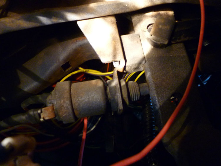
Thank you for the brake switch recommendation. For others reading this thread, Tom recommended an 85' monte carlo brake switch. Another quick question for you: I don't plan on running cruise control, do I need to buy a brake switch capable of supporting cruise control for it to work properly? I know I'm preaching to the choir, but my old brake switch has two connection terminals (pic below)... should the newer switch have four terminals for the CC?
 06-25-2012, 11:20 PM
#92
On The Tree
Thread Starter
Join Date: Sep 2010
Location: San Luis Obispo CA
Posts: 155
Likes: 0
Received 0 Likes
on
0 Posts
June 24, 2012
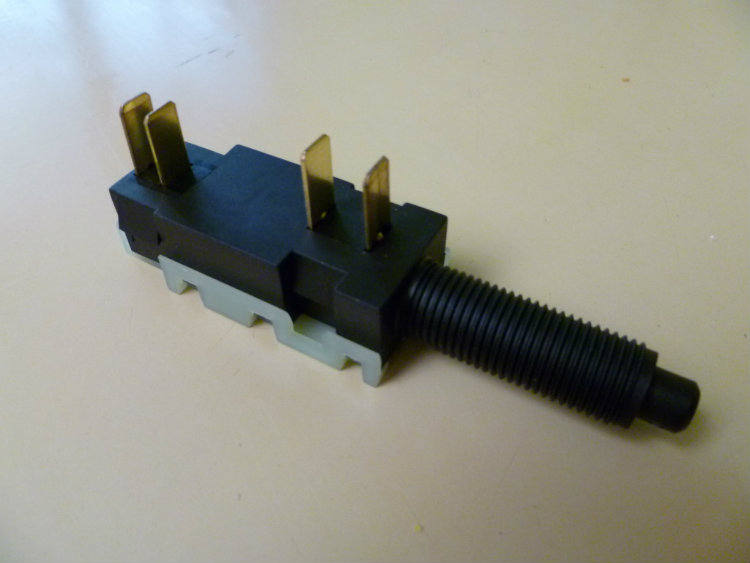
I went with the brake switch Tom suggested, in fact, it's perfect for this type of swap (Thanks Tom). Here's a pic of the 85' Monte Carlo brake switch:
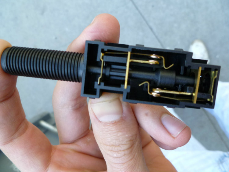
Just in case you were wondering how a majority of these switches work (hell, I was curious so I took it apart):
My finger is pressing the button in, which is the normal position of the brake pedal assembly when the brake is NOT being pressed. When the brake is applied, the button is released and the two electrodes (top portion in the picture) make contact and complete the circuit for your brake lights to come on.
At this same time, the exact opposite happens for the other two electrodes (bottom portion of the switch) . The button is released and the electrodes cease to make contact, breaking the connection and telling the torque converter clutch you're slowing down.
The plastic rod in the middle that runs the length of the switch is moving when the button is pressed or released.
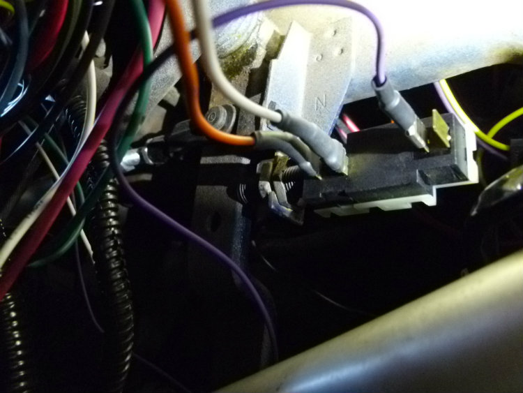
Need to know how to wire it? This is a helpful link: Brake Switch Wiring. I Looked past all the relay stuff... IMO it's not necessary. Here's a pic of my switch installed, except the +12v source, which I still need to connect.
I went with the brake switch Tom suggested, in fact, it's perfect for this type of swap (Thanks Tom). Here's a pic of the 85' Monte Carlo brake switch:
Just in case you were wondering how a majority of these switches work (hell, I was curious so I took it apart):
My finger is pressing the button in, which is the normal position of the brake pedal assembly when the brake is NOT being pressed. When the brake is applied, the button is released and the two electrodes (top portion in the picture) make contact and complete the circuit for your brake lights to come on.
At this same time, the exact opposite happens for the other two electrodes (bottom portion of the switch) . The button is released and the electrodes cease to make contact, breaking the connection and telling the torque converter clutch you're slowing down.
The plastic rod in the middle that runs the length of the switch is moving when the button is pressed or released.
Need to know how to wire it? This is a helpful link: Brake Switch Wiring. I Looked past all the relay stuff... IMO it's not necessary. Here's a pic of my switch installed, except the +12v source, which I still need to connect.
09-05-2012, 09:13 PM
#93
Teching In

Join Date: Mar 2009
Location: Georgia Peach
Posts: 31
Likes: 0
Received 0 Likes
on
0 Posts
so many questions as I am doing a 2004 got and auto in my 67 nova right now. I have complete TCI setup in mine, they told me to buy a muscle car oil pan, I did it today passenger side bolted up but driver side is 1/2" away from the hole! It's hitting the power rack and pinion. I sent pics to them and am awaiting an answer now. Any suggestions?
09-06-2012, 08:25 AM
#94
On The Tree

Join Date: Apr 2011
Location: Vancouver, WA
Posts: 129
Likes: 0
Received 0 Likes
on
0 Posts

so many questions as I am doing a 2004 got and auto in my 67 nova right now. I have complete TCI setup in mine, they told me to buy a muscle car oil pan, I did it today passenger side bolted up but driver side is 1/2" away from the hole! It's hitting the power rack and pinion. I sent pics to them and am awaiting an answer now. Any suggestions?
Muscle Car Pan with a TCI MII clip.
Fbody Pan in a TCI MII clip.
As for the motor mounts not lining up you will probably have to install them with the mounts and adapter plates a little loose so you can move them around. Once everything lines up you will have to tighten them the best you can. Lift the motor up/out and scribe the motor mount location on the adapter plate. Remove the motor mount tighten the hidden bolts on the adapter plates and reinstall the mounts.

 09-10-2012, 02:22 AM
#97
On The Tree
Thread Starter
Join Date: Sep 2010
Location: San Luis Obispo CA
Posts: 155
Likes: 0
Received 0 Likes
on
0 Posts
I just did the exact same thing the other day. It's good to hear that it worked out for you since mine isn't running yet. peace of mind. Thanks for the post.
09-10-2012, 02:27 AM
#98
On The Tree
Thread Starter
Join Date: Sep 2010
Location: San Luis Obispo CA
Posts: 155
Likes: 0
Received 0 Likes
on
0 Posts
As for the motor mounts not lining up you will probably have to install them with the mounts and adapter plates a little loose so you can move them around. Once everything lines up you will have to tighten them the best you can. Lift the motor up/out and scribe the motor mount location on the adapter plate. Remove the motor mount tighten the hidden bolts on the adapter plates and reinstall the mounts.
09-25-2012, 12:47 AM
#100
On The Tree
Thread Starter
Join Date: Sep 2010
Location: San Luis Obispo CA
Posts: 155
Likes: 0
Received 0 Likes
on
0 Posts
Unfortunately, I'm not much help when it comes to the power racks, but I may be able to point you in the right direction. I imagine Church Boys Racing could shed some light on your issue. They deal with power racks quite a bit.