When you click on links to various merchants on this site and make a purchase, this can result in this site earning a commission. Affiliate programs and affiliations include, but are not limited to, the eBay Partner Network.
Since I figured out on 2003 + PCM's there isn't a good way to wire the relays to an ac pressure switch to let the PCM control the fans for AC like the early PCM's I have to re-think it
So the best option is to let the PCM still control the fans based on engine temp and load.
But wire a Vintage air trinary switch into the low fan relay (terminal 85 on relay 1) to control the fans with AC on that way.
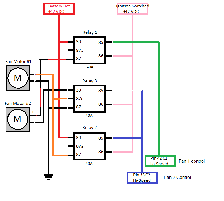
But I am totally confused, I want to wire three relays to control the fans similar to the fbody set up (I have dual Fbody fans)
As you can see here the PCM provides a ground on terminal 85 on relay 1 and relay 3.
I want to tie the ground output of the trinary switch to the same output of the PCM Fan 1 trigger.
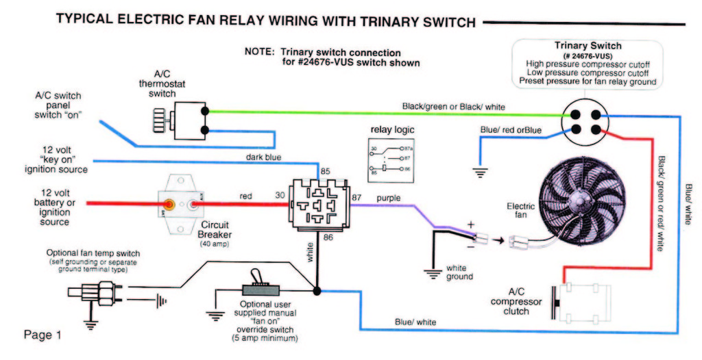
But looking at the trinary switch diagram the ground output of the switch to turn the fan on goes to pin 86 of the relay from the blue / white wire....
But Pin 86 of the fan relay above goes to ignition switched 12v +, so it's essentially reversed.
So i am confused at this point, any idea? Can i still wire the trinary switch trigger to terminal 85 of relay 1 and ignore this diagram below?
The way the 2 speed f body fans are wired are to run in series or parallel.
You can use the trinary switch to provide a ground to one of the ecu speed pins.
If you spice into the low speed, both would be on low any time the trinary switch is closed. High speed would work as it does normally.
If you splice into the hi, only one fan would run at hi speed if engine wasn't hot and the trinary switch closed.
Thanks, so basically what your saying is ignore the 2nd diagram and splice the output from the trinary switch into the same spot the low speed fan control is coming in at on Relay # 1 , terminal 85?
If I want both fans to run at low speed when AC is on
Well the 2nd diagram is doing the same thing, grounding the fan relay with the trinary, a manual switch, or the temp sensor switch (what your ecu does). Just splice the trinary into that low speed fan wire. Even if the engine temp isn't high where you need a fan (ie highway) the fan will kick on at low speed if the AC pressure gets too high.
High speed fan will kick on normally.
Why do you say there is no way for a 03+ to work with a pressure switch? You need to look at an express van or truck. If you are not using that OS then it will have to be programmed to the ac type.
Why do you say there is no way for a 03+ to work with a pressure switch? You need to look at an express van or truck. If you are not using that OS then it will have to be programmed to the ac type.
I have a 2004 PCM with the express van tune. I also have HPtuners so I can change any setting I need to
There's a section in there for adding the AC pressure switch and controls that says "letting the PCM control the fans with an ac pressure switch will not work on 2003+ systems". Something to do with the way GM changed the AC control.
If they are wrong on that I would LOVE to let the PCM control the AC but that's what I was going on.
There's an excerpt of this on the web, I'll see if I can find it
Well the 2nd diagram is doing the same thing, grounding the fan relay with the trinary, a manual switch, or the temp sensor switch (what your ecu does). Just splice the trinary into that low speed fan wire. Even if the engine temp isn't high where you need a fan (ie highway) the fan will kick on at low speed if the AC pressure gets too high.
High speed fan will kick on normally.
Why do you say there is no way for a 03+ to work with a pressure switch? You need to look at an express van or truck. If you are not using that OS then it will have to be programmed to the ac type.
If I can use a 2003+ PCM for what I am wanting to do please let me know, I'm in the middle of wiring everything right now
OK the guy is partially right. None of the vehicles that I know of that use a fixed compressor use dual fans -vans, trucks. The switch does not turn on the fan because it already has a mechanical fan running. The pcm needs to be wired and programmed for a dual fan setup. All the pcm's from 03+ are basically the same with some minor differences such as IAC drivers that some have and some do not. Guys miss the fact that a particular car can have different wiring due to how things are controlled. You need to find a vehicle that has dual fans and wire it as such then program it for the dual fans. Example I am using a 04 GTO tune that turns on my ac with a 12 volt request. It is basically a 02 Camaro wiring setup with a newer pcm an OS. People say it cannot be done or will not work. The GTO uses the BCM to turn on the ac and the fan there is no wiring at all showing what I did. Why did it work? All the 03+ pcms are just newer versions of the old 411 but with faster processors and more memory.
have a express Van tune, with the added wiring converting my 5.3 harness to DBC
I also have the added wiring for Fan 1 and Fan 2 in the correct pin-outs on the PCM connector....going to a set of three relays wired like the Fbody diagram floating around. PCM has the settings for both fans enabled.
So I should be ok adding the three wire AC switch, providing that feature is enabled and the wiring is in the correct pin-outs?
If so I would def rather go that route than adding a trinary switch. I already have the parts to do that
If you're wanting to use the three wire pressure sensor, I believe you'll need a Silverado tune since they are the ones that used it. The Express van uses high and low switches. From what I have been seeing, you have to use what ever system (3 wire sensor, or two on-off switches) your OS was originally set up for. Getting around the serial data request, which is what the guy in the book is referring to, is the easy part. It can be changed in the tune to a 12v request. Here's a thread on it. https://ls1tech.com/forums/conversio...ector-ecu.html
Just an FYI, I'm running 2 truck DBW conversions (02 LQ9 & 05 L59) with aftermarket AC and no AC request to the ecu. No issues at all.
The LQ9 runs a mechanical fan and electric controlled by temp and AC trinary.
The L59 runs 2 electrics. One by ecu temp (lower temp), the other by temp (higher temp) and Trinary. Both single speed.
Both set ups run the motor and cool the AC great.
Thanks for the heads up, I think I am going to do the trinary switch set-up instead. Trying to research this using a PCM control (for my application) gets overwhelming fast.
I also have a 04 silverado system that has no a/c request( serial) . I use the factory a/c request switch and low pressure switch to control the compressor from vehicle it came with ( 82 c10) . I added the high pressure trinary switch from the 04 donor and put the 3 wires in the pcm from the trinary . This controls the fans perfect . This is how gm designed the system to work . I is independent of a/c request . It only sees pressure to control the fans . There is some advantages to this . Delay's fans on engine start . Also will shut off fans at engine speeds above 35 to 40mph when not needed . Mine had worked perfect thru a couple summers . You will need to to use the three relay fan control like gm uses and dual fans for this to work proper .
In my Gen IV computer setup when I send ground from the trinary to the ground output from the PCM to trigger the Fan relay, it causes a Check Engine Light, when the computer sees another ground on that circuit.
A diode could separate, but I chose to wire a parallel relay which triggers the cooling fan just from the trinary pressure switch. I use a small bus bar mounted on the fan shroud to attach the 12V+ outputs from the parallel relays. An isolated stud would work as a bus bar, too.
Of course, at some times, both relays are powering the fan. There is no issue with that.
Hope this alternate solution might help you.
See the busbar in the bottom left corner of the shroud:
Thanks, I thought about adding a 2nd relay just for the trinary switch. Didn't think about the check engine light issue.
I wonder what kind of diode would I need if I went the route of just using that?
I still have some diodes left from my car audio days that I used to isolate grounding sensors for alarms, N1006 or N10046..they were called something like that. They are black with a gray band I think.
Given the low cost and simplicity of wiring another relay, that was a no-brainer for me. I ordered a 100 pack of diodes for $5 from Amazon and then decided I didn't have a good way to cleanly wire them in (they just have the single wire leads attached.) Probably could have used non-insulated butt connectors and then shrink wrapped the whole thing. Still, I was concerned about reliability of the diode and connectors, were it to break.
I used one of those bussman relay / fuse boxes all in ones and located the trinary relay there as well as head light relays (high and low beams). The box has 5 relay circuits and I'm using four. Two for the fans (one triggered by ECU and one by trinary) and then the two for the headlight circuits. I run a large feed lead from alternator lug. Maybe 4 or 8 gauge. Note, my large SPAL fan keeps things cool even in high ambient weather teams (up to 95F, I've driven). But startup current spikes at over 30 amps. Steady state is about 25 amps. I had to track down a 40amp mini fuse for that box to keep it from blowing fuses every time it starts.
Good luck!
I added the fuse / relay box in the driver's wheel well. Lots of ways to do this, of course.
I've heard about the MIL with the additional ground, but never got one on my Gen III. But I think it was wired to the recirc, used on the trucks for 2nd fan too.
7 Most Reliable High-Performance Engines GM Has Ever Built
Slideshow:These GM engines didn't just make huge power, they survived abuse, boost, track days, and six-digit mileage with a reputation for refusing to quit.
6 Common C5 Corvette Failures and What's Involved In Repairing Them
Slideshow: From wobbling harmonic balancers to failed EBCMs, these are the issues that define long-term C5 ownership and what repairs typically involve.
Retro Modern Bandit Pontiac Trans AM Comes With Burt Reynolds' Autograph
Slideshow: A modern Camaro transformed into a retro icon, this limited-run "Bandit" build blends nostalgia with brute force in a way few revivals manage.
Top 10 Greatest Cadillac V Series Performance Models Ever, Ranked
Slideshow: Cadillac didn't just crash the high-performance luxury vehicle party, it showed up loud, supercharged, and occasionally a little unhinged...
Coachbuilt N2A Anteros Is an LS2-Powered C6 Corvette In Italian Clothes
Slideshow: A one-off sports car that looks like a vintage Italian exotic-but hides a C6 Corvette underneath-just sold for the price of a new mid-engine Corvette.