
LS1 Swap FAQs

 04-29-2006, 04:54 PM
#22
On The Tree

Join Date: Oct 2005
Posts: 161
Likes: 0
Received 0 Likes
on
0 Posts
That GTO pan looks almost identical to a Holden pan which I ended up modifying to install an LS1/6 in my '88 BMW M3. This forum is an awesome information source. I wish I had known about it when I was working on the wiring harness for my conversion. I didn't notice pin-outs for an LS7. That would be an excellent addition.
06-06-2006, 04:01 PM
#24
TECH Apprentice
Join Date: May 2006
Location: Kansas City metro area
Posts: 360
Likes: 0
Received 0 Likes
on
0 Posts

Another clutch story!
Just in case anyone else is struggling with a hybrid application like me and is needing to know about an LS1 to non-T56 clutch setup this is what worked for me.
I am installing an LS1 from a '98 Camaro into my '62 Chevy II Nova. I did not want to cut up the floor boards and wanted to feel like I was 18 again so I am using a Muncie 4 speed. I am not sure I wouldn't just use the T56 next time but anyway.
My dropout LS1 had the flywheel and starter. The stock LS1 clutch is a 12" or so. I figured I could just buy a new pressure plate and then a disc to match the Muncie input shaft. Most suppliers do not list the pressure plate separately now. I could not use a stock disc since it was 26 spline instead of 10. Well RAM offers all of the pieces separately. I got an 11 inch LS1 pressure plate (402L) and a new 11 inch 10 spline clutch disc. After removing the locating pins and getting the flywheel surfaced the assembly went together fine. It was at this time that a couple of items became apparent: the big flywheel would not fit in my bell housing and there may be an issue with the pilot bearing.
Chevy IIs were never available with the big 168 tooth flywheel. The 168 tooth flywheel is closest to the LS1 size. Since no stock Chevy II bell housing can be used for the big flywheel there was a problem. Chevy IIs also have the clutch fork at a peculiar angle. Instead of coming out at the 3:00 position like all of the other models it is at a 4:00 to 5:00 position. If not for this a stock bell housing for the big flywheel would have worked. The only solution I could think of was a scattershield. Same issue of clutch fork position with a scattershield of course. Lakewood makes a Chevy II scattershield so that is what I got. First thing I noticed was that the block plate would not bolt on an LS1. The bolt pattern is fine but there are castings that bolt on the back of the block that stick out past the mating surface of the block to bell housing unlike a regular small block. I carefully marked the areas that needed to be cut and went for it. The block plate fit fine then, the scattershield bolted right up, everything cleared.
This is when I read a posting about the pilot bearing being short. The Muncie input shaft started in the stock bearing but did not engage far enough. The back of the LS1 crank has 2 different bores. The deepest one is where the stock bearing sets. The one closest to the clutch is much larger. The posting said that you could either have a longer pilot bushing machined (which is sweet) or get a special bearing that fit in the larger bore. I went with that bearing and left the original bearing there. It did not fit tight in the crank so I used some shim stock to tighten it up. Everything fit great then and was well supported.
Only thing left was the throwout bearing. The scattershield may have messed with the spacing but I ended up needing the old 'long' bearing. With it the clutch fork is positioned right, there is plenty of throw, and it is solid. If that helps with even one question out there I will be pleased.
06-07-2006, 09:51 AM
#25
These were collected from various posts:
For rubber elbows, reducers, connectors and tubing
http://www.intakehoses.com/
http://www.airflow.com
Try www.samcosport.com for silicone tubing
Try www.woolfaircraft.com for pre-bent aluminum tubing
Bobs muffler in bakersfield Ca. can madrel bend up to 4" tubing http://www.bobsmuffler.com/about.htm
Pat
06-07-2006, 11:11 AM
#26
TECH Veteran
iTrader: (3)
Join Date: Feb 2004
Location: Lynnwood, WA (North of Seattle)
Posts: 4,729
Likes: 0
Received 0 Likes
on
0 Posts
Originally Posted by Stu Cool
Bobs muffler in bakersfield Ca. can madrel bend up to 4" tubing http://www.bobsmuffler.com/about.htm
Pat
Pat
 06-12-2006, 02:30 AM
#27
Teching In
Join Date: Oct 2005
Location: Southern California
Posts: 20
Likes: 0
Received 0 Likes
on
0 Posts
The J1 connector wires go from the rest of the car to the ECM and back out. The other two connectors J2 and J3 on the E40 ECM are both for the motor and M6 trans harness. Any wiring wizards want to take a shot figuring out what�s exactly needed for a conversion for the general public? 
2005 GTO LS2 E40 Engine Control Module Pin Assignments for the blue J1 Connector
Pin - Wire Color - Function
1 TN/BK High Speed GMLAN Serial Data Bus+
2 TN High Speed GMLAN Serial Data Bus-
3 Not Used
4 BN/WH Check Engine Indicator Lamp Output
5 Not Used
6 Not Used
7 BN Electronic Throttle Pedal Position Return 1
8 PU Electronic Throttle Pedal Position Return 2
9 Not Used
10 BN Engine Control Relay Coil Control
11 Not Used
12 Not Used
13 YE Starter Relay Output-Coil
14 PK Ignition 1 Voltage
15 Not Used
16 Not Used
17 Not Used
18 YE Accessory Voltage
19 OG Ignition 3 Voltage
20 OG/BK Battery Positive Voltage
21 PU/WH VSS Signal
22 BU Electronic Throttle Pedal Position Signal 1
23 Not Used
24 GN Fuel Tank Pressure Sensor Signal
25 Not Used
26 GN/BK A/C Refrigerant Pressure Sensor Signal
27 Not Used
28 Not Used
29* TN Electronic Throttle Pedal Position 5-Volt Reference 2
30 GN A/C Refrigerant Pressure Sensor Signal 5-Volt Reference
31 GY Fuel Tank Pressure Sensor 1, 5-Volt Reference
32 BU/RD Stop Lamp Switch Signal
33 Not Used
34 Not Used
35 WH/BK Electronic Throttle Pedal Position 5 Volt Reference 1
36 OG/BK Low Speed Cooling Fan Relay Control
37 PU Fuel Gage Sensor Signal
38 GY Extended Travel Brake Switch Signal
39 Not Used
40 Not Used
41 L-BU Electronic Throttle Pedal Position 2
42 YE Reverse Lockout Solenoid Control
43 PU/WH CPP Switch Signal
44 Not Used
45 GN/WH Fuel Pump Relay Feed-Coil
46 BN Cruise Control Release Signal
47 Not Used
48* BN/RD Tachometer Signal
49 Not Used
50 Not Used
51 GN/BU Park/Neutral Position Switch Park Signal
52 PU Crank Voltage
53 Not Used
54* WHT To BCM Connection 1 position 16
55 TN A/C Refrigerant Pressure Sensor Signal
56 BU/WH High Speed Cooling Fan Relay Control
* Denotes a difference from the Factory Service Manual (FSM) and my harness.
29 FSM has the color listed as TH instead of TN.
48 FSM doesn't list the red stripe (BN/RD), only listed as solid brown (BN).
54 Is listed as Not Used. I split open the loom and followed it to the Body Control Module (BCM).
Notes:
The 2005 used the E40 but didn�t use the CANN operating software until the following year.
HP Tuners can delete the VATS in both versions.
Tha E40 does have faster processing then previously used PCM�s and is expected to be used with GM�s Displacement On Demand system (DOD).
This is a semi stand alone unit for the motor and 6 speed trans, a seperate PCM is used with auto trans cars. Information is still shared with the Body Control Module (BCM).
Since this is going to be around for awhile please post tips, relevant links and LS2 information for idiots like me using one for their conversions and I�ll do the same as I figure the wiring out.
Thanks for your time
06-13-2006, 08:50 AM
#28
Teching In

Join Date: Jun 2006
Location: Bartlesville, OK.
Posts: 10
Likes: 0
Received 0 Likes
on
0 Posts
This is what i did, I went to http://www.alldatadiy.com/ and bought a subscription to my year TA (or at least the year of the enging trans i am using), for like 25 bucks you get access to ALLDATA repair document, service bullitens and tons more info along with WIRING diagrams and connector pictures and locations, well worth the money. (And no i don't work for alldata) I spent about an hour and downloaded and printed 40 pages of diagrams for my car, after looking at them I felt much better tackling making the changes to my harness for "stand alone" use, i am also using the dash that came out of the same ta. Hope this helps, I looked at all the free stuff out there and it helped but man it much easyer to log on and get the data i need in one place, and the subscription is for one year. If you don't know, ALLDATA is a big supplier of shop repair manuals closer to OEM than chiltons or haynes, etc. Hope this helps
PS. 25 dollars gets a 1 year subscription to one vehicle
PS. 25 dollars gets a 1 year subscription to one vehicle
06-23-2006, 11:50 PM
#29
I have Alldata through work and used that (for the '98 harness) and Shoebox's site (for my '94 car) and it comes in handy when you reach the 'scratch my head now' times.
Originally Posted by fasthuhpat
This is what i did, I went to http://www.alldatadiy.com/ and bought a subscription to my year TA (or at least the year of the enging trans i am using), for like 25 bucks you get access to ALLDATA repair document, service bullitens and tons more info along with WIRING diagrams and connector pictures and locations, well worth the money. (And no i don't work for alldata) I spent about an hour and downloaded and printed 40 pages of diagrams for my car, after looking at them I felt much better tackling making the changes to my harness for "stand alone" use, i am also using the dash that came out of the same ta. Hope this helps, I looked at all the free stuff out there and it helped but man it much easyer to log on and get the data i need in one place, and the subscription is for one year. If you don't know, ALLDATA is a big supplier of shop repair manuals closer to OEM than chiltons or haynes, etc. Hope this helps
PS. 25 dollars gets a 1 year subscription to one vehicle
PS. 25 dollars gets a 1 year subscription to one vehicle
07-28-2006, 07:50 PM
#30
12 Second Club

Join Date: May 2005
Posts: 41
Likes: 0
Received 0 Likes
on
0 Posts
Originally Posted by SatisTraction
i will have my pan welded locally instead of shipping it off. The question is what material sould i use for the notch?
posted by 'JustDreamin'
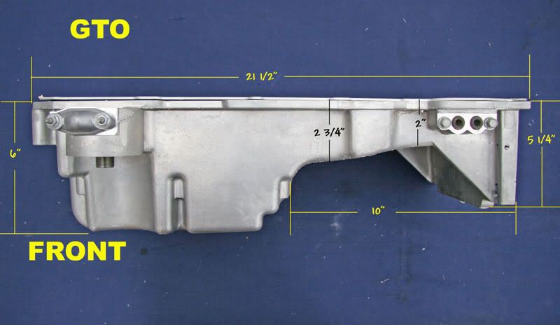
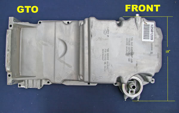
According to Will Handzel's book, the Oil Pan is cast from 356-T6 aluminum (listed in a chart on page 26).
Out of curiosity, I looked up 356-T6 in one of my engineering texts, and that alloy has a fairly high silicon content (~7 %) and 0.4 % Magnesium. In T6 heat treated condition, it should have about 38 kpsi tensile strength.
Knowing that info should help select an alloy to use for parts and pieces.
My texts show there isn't a "perfect" match in a wrought alloy (stuff you'd find in barstock form) but 6061 seems to be the closest.
posted by 'JustDreamin'
According to Will Handzel's book, the Oil Pan is cast from 356-T6 aluminum (listed in a chart on page 26).
Out of curiosity, I looked up 356-T6 in one of my engineering texts, and that alloy has a fairly high silicon content (~7 %) and 0.4 % Magnesium. In T6 heat treated condition, it should have about 38 kpsi tensile strength.
Knowing that info should help select an alloy to use for parts and pieces.
My texts show there isn't a "perfect" match in a wrought alloy (stuff you'd find in barstock form) but 6061 seems to be the closest.
08-21-2006, 03:28 AM
#31
TECH Regular
Join Date: May 2005
Location: Bay Area, CA
Posts: 406
Likes: 0
Received 0 Likes
on
0 Posts
Thought I'd share my fuel system layout for my '73... No pics, but what the hell.
Since Im a cheap *** and demanded perfect reliabilty from my fuel system (I hope, time will tell) and I didn't want an external pump, and didn't want to buy a new tank or have a custom one made... I simply adapted the LS1 bucket system to work. What I did was shorten the stock LS1 bucket as much as possible, down to the height of the pump. I tossed the whole top half of the system in the trash, minus the springs. Then I cut a hole in the top of my stock 73 tank, and dropped the bucket in. I then got a third gen sending unit, tweaked it to fit into the 73 tank, tweaked the float/sending unit to read correctly, and ran a fuel injection hose from the fuel pump to the 3rd gen supply line. The height of the pump and rubber line poses a problem with kinking as it exits the pump as it is right ont the top of the tank. I set the pump in the bucket slightly crooked and then inserted a spring into the fuel injection hose to prevent kinking. Conveniantly, one of the springs you saved from the 4th gen fuel pump assembly fits perfectly in a 3/8 hose. I then ran a return line from the 3rd gen unit back into the bucket assembly. Went ahead and made a cover for the top of the tank and sealed it down. Solves every issue I was concerned with. Works just like a factory setup, only it was $40 bucks for hose and clamps and the 3rd gen sending unit.
Since Im a cheap *** and demanded perfect reliabilty from my fuel system (I hope, time will tell) and I didn't want an external pump, and didn't want to buy a new tank or have a custom one made... I simply adapted the LS1 bucket system to work. What I did was shorten the stock LS1 bucket as much as possible, down to the height of the pump. I tossed the whole top half of the system in the trash, minus the springs. Then I cut a hole in the top of my stock 73 tank, and dropped the bucket in. I then got a third gen sending unit, tweaked it to fit into the 73 tank, tweaked the float/sending unit to read correctly, and ran a fuel injection hose from the fuel pump to the 3rd gen supply line. The height of the pump and rubber line poses a problem with kinking as it exits the pump as it is right ont the top of the tank. I set the pump in the bucket slightly crooked and then inserted a spring into the fuel injection hose to prevent kinking. Conveniantly, one of the springs you saved from the 4th gen fuel pump assembly fits perfectly in a 3/8 hose. I then ran a return line from the 3rd gen unit back into the bucket assembly. Went ahead and made a cover for the top of the tank and sealed it down. Solves every issue I was concerned with. Works just like a factory setup, only it was $40 bucks for hose and clamps and the 3rd gen sending unit.
08-21-2006, 10:17 AM
#32
TECH Apprentice
Join Date: May 2006
Location: Kansas City metro area
Posts: 360
Likes: 0
Received 0 Likes
on
0 Posts
I have searched the site here and got the tips on where to get a plug for the the sensor and have the specifics for how I did it. Advance Auto Parts has a replacement oil drain plug that fits perfectly. It is a M20-1.50 plug with a gasket that looks like an - oil pan drain plug! Cost about $2.00, MotorMite Oil-Tite part number 65221. They are back with the oil change stuff. Fits and looks good.
10-01-2006, 02:40 PM
#34
this is for the corvette fuel pressure regulator, in the 3/8 female outlet side.
hey guys, I was looking through autozone's pipe fittings, and I found exactly what we need. it's part number 27844, and it is the flare on one end, and a 3/8 inverted flare on the other. now all you'd need, is a 3/8 I/F to -6an male fitting. it's about five bucks.
olly
hey guys, I was looking through autozone's pipe fittings, and I found exactly what we need. it's part number 27844, and it is the flare on one end, and a 3/8 inverted flare on the other. now all you'd need, is a 3/8 I/F to -6an male fitting. it's about five bucks.
olly
10-07-2006, 10:26 PM
#35
Originally Posted by SatisTraction
theres one more wire not listed there.. its a thick purple wire that goes to the starter.
when it gets +12v, the starter turns the motor over.

I need to clarify on the thick purple wire for anyone using Wait4Me Performance's harness. The stub of a wire left behind is a little confusing - you'll need to tap your stock starter wire into this stub they've left for you.
It was not clear to me at first.
Last edited by shifty`; 10-08-2006 at 11:20 PM.
10-08-2006, 07:32 AM
#36
Originally Posted by shifty`
I need to ask about this - Does this thick purple wire coming out of the PCM go OUT to the starter solenoid, or do I tie this into the purple wire coming from the ignition switch?
Ign Switch "START" Pole -> Big Purple Wire -> Starter Solenoid
10-08-2006, 10:25 AM
#37
People ask so that information that needs to be clarified is all in one post Search for "purple wire ignition", hte question gets asked frequently
Just in case anyone else is using Wait4Me reworked harness and is installing into an older GM pickup (60-72 at least), take your original purple wire that ran to the starter and tie that into the purple (starter sol) lead that W4M left for you. Your original pink HEI ignition wire (if you have/had HEI) and use that as a tie in for your fan relays (if you have the old white cloth wrapped wire for points, you'll need to run a new one). You can ignore your blue (oil pressure dummy sensor) and your water temp dummy gauge lines. You'll need to supply the appropriate power for the red and orange wires that W4M left for you as indicated on the stickers, and you'll need to setup the relay for the fuel pump as well.
If your engine/swap came with a 1-wire alternator, you can delete your factory regulator which is typically mounted on the radiator support by the horn, under the washer fluid box (at least on 67-72 models). You will need to relocate the ground for the driver's side headlight and tie together your power wires accordingly (take a quick gander at them - it will make sense) so that you're still running a single positive line from the battery into the junction/fuseblock harness.
Search for "purple wire ignition", hte question gets asked frequently Just in case anyone else is using Wait4Me reworked harness and is installing into an older GM pickup (60-72 at least), take your original purple wire that ran to the starter and tie that into the purple (starter sol) lead that W4M left for you. Your original pink HEI ignition wire (if you have/had HEI) and use that as a tie in for your fan relays (if you have the old white cloth wrapped wire for points, you'll need to run a new one). You can ignore your blue (oil pressure dummy sensor) and your water temp dummy gauge lines. You'll need to supply the appropriate power for the red and orange wires that W4M left for you as indicated on the stickers, and you'll need to setup the relay for the fuel pump as well.
If your engine/swap came with a 1-wire alternator, you can delete your factory regulator which is typically mounted on the radiator support by the horn, under the washer fluid box (at least on 67-72 models). You will need to relocate the ground for the driver's side headlight and tie together your power wires accordingly (take a quick gander at them - it will make sense) so that you're still running a single positive line from the battery into the junction/fuseblock harness.
Last edited by shifty`; 10-08-2006 at 11:18 PM.
10-11-2006, 03:15 AM
#38
On The Tree

Join Date: Apr 2004
Location: Oslo, Norway, Europe
Posts: 166
Likes: 0
Received 0 Likes
on
0 Posts
could someone update the first post with 2003 2004 ++ pin out assignments? would be great, im gonna start on installing a 2004 gto engine, and the plugg assignments.
10-11-2006, 05:46 PM
#39
Launching!
Join Date: Dec 2005
Posts: 213
Likes: 0
Received 0 Likes
on
0 Posts
i purchased autozones 27844, dont think it is correct 67rs....nipple is not long enuff to reach o-ring in corvette filter, the collar is too thick to click into place... dont wanna chance damaging filter...
10-11-2006, 09:59 PM
#40
This has been a topic of interest lately. One alternative to connect the steam vent hose is to drill a hole in the top of the water pump. I did this on my engine and it works great. I used a 1/8 NPT elbow fitting. For the 1/8 NPT, the drill size is Letter R, decimal inches is .339. Then carefully tap it. I did this with the water pump on the motor. To safe guard against filings, I put some grease on the drill bit to hold them and also put my shop vac up to the inlet to pull out any shavings. Once you have the hole drilled and tapped screw the fitting in, but don't over tighten it as the NPT is tapered and if you go too far, it might crack the housing. The water pump housing is cast aluminum and it is not real thick. I used teflon tape on mine, but I am not sure if it is needed. I by-passed the throttle body and removed the tubes. Here is a picture of it installed.
Pat
Pat