


Alternator with battery disconnect

Thread Starter
Staging Lane
Joined: Sep 2008
Posts: 92
Likes: 1
I've searched but have not found the definitive answer. What is the best way to wire the alt with a trunk mount 2 pole battery disconnect? The engine and alt is a 99 LS1 from a Camaro. It appears that switching the output lead will blow the regulator (plus long, heavy wiring). Will switching the PCM to alt wire do the job with no problems? (Nice small, light, wires) What is correct? Thanks
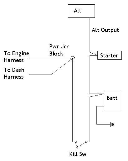
Well you got me interested. this set up looks promising (from http://www.ssdiv.com/master.html). Seems like as long as you kill power to the alt charge lead it will turn off the alternator. No need to interrupt the output lead, although I see many switches say to do so.
The resistor is a ballast-type ignition resistor, and almost any rating from 3 to 15 ohms will work, provided it can handle 10-20 watts. The resistor should come with the cut-off master switch if you get the right one. Pegasus and Racer's Wholesale both carry these switches as complete kits. Calterm, OMP, and Hella are brands that I've used and respect.
Originally Posted by http://www.ssdiv.com/master.html
The resistor is a ballast-type ignition resistor, and almost any rating from 3 to 15 ohms will work, provided it can handle 10-20 watts. The resistor should come with the cut-off master switch if you get the right one. Pegasus and Racer's Wholesale both carry these switches as complete kits. Calterm, OMP, and Hella are brands that I've used and respect.
Thread Starter
Staging Lane
Joined: Sep 2008
Posts: 92
Likes: 1
Thanks guys. That's the first time I saw a resistor mentioned. I guess that bleeds off the spike from the alt when disrupted. The S&S drawing also works well for me since I plan to use a trunk mount remote solenoid which makes the wiring different (no hot lead at starter). The question now is, where should I interupt the ignition? How about the "IGN hot to PCM"? Will that kill everything? Thanks again! (Pop N Wood, you're even older than me! What are we doing with these young guy cars?)
i did mine like Smo's GTO dia, i ran #4 all the way back to the bat side of the switch-if you run to small of a wire, the rest. in the line will burn up the alt, it will see the rest. as a load, and keep charging
the only thing i didnt do was add a fuse, which i need to-curious what kind of heavy duty style, im thinking maybe a cir breaker type-when not using the car, i turn off the switch, but the alt lead is still hot to the front-i did use the split plastic to protect the wire though
the only thing i didnt do was add a fuse, which i need to-curious what kind of heavy duty style, im thinking maybe a cir breaker type-when not using the car, i turn off the switch, but the alt lead is still hot to the front-i did use the split plastic to protect the wire though
Thread Starter
Staging Lane
Joined: Sep 2008
Posts: 92
Likes: 1
I'm beating this subject to death but I try to do things right (I can't afford to do it twice!) When using a resistor to bleed off the alt surge, does that have any bad effects on other electrical components? Not being an electronics guy, does the proper resistor just bleed off surges higher than 12-14 volts and not short out other electronics such as the PCM?
Trending Topics
did you ever get yours done? i need to do this on my 99 vette and from the looks of it i will need to remove the factory large red wire off the back of the alt and connect it over at the power juncution near the fuse box. then run a wire from the back of the alt to the battery positive. does this seem like it would work?
LS1 Tech Stories
The Best V8 Stories One Small Block at Time

6 Common C5 Corvette Failures and What's Involved In Repairing Them
Pouria Savadkouei
Retro Modern Bandit Pontiac Trans AM Comes With Burt Reynolds' Autograph
Verdad Gallardo
Top 10 Greatest Cadillac V Series Performance Models Ever, Ranked
Pouria Savadkouei
Top 10 Most Powerful Chevy Trucks Ever Made!

Hennessey's New Supercharged Silverado ZR2 Has 700 HP
Verdad Gallardo
Coachbuilt N2A Anteros Is an LS2-Powered C6 Corvette In Italian Clothes
Verdad Gallardo
Awesome K5 Blazer Restomod Comes With C7 Corvette Power
Verdad Gallardo
10 Camaros You Should Never Buy

10 LS Engine Myths That Refuse to Die
Verdad Gallardo
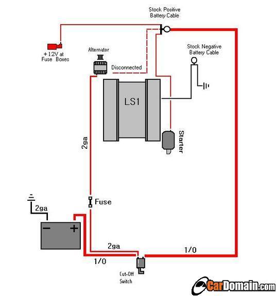
With this diagram where it has the dotted line going from the altenator to the stock positive battery cable, it says disconnected? does that mean it disconnected when i have the switch off or what?
Im doing my s10 and was going to do something like this...
BAttery in the bed, ground from the batt to the frame, positive to one post on the cut off switch then from the other post up to the starter. from the starter run a 4 gauge to a dist block on the fire wall to get all my constant power (to the altenator, and constant power for harness and anything else i need) then a smaller gauge wire from the constant dist block to the ignition then out of the ignition to another dist block that will be for keyed power supply... so basically from the cutoff switch to the starter, from the starter to a dist block, then grab my constants from that block, then run off that block through the ignition to another block to get all my keyed supply off of...
Will this work properly and shut everthing off when i kill the switch?
Thread Starter
Staging Lane
Joined: Sep 2008
Posts: 92
Likes: 1
I'm glad I'm not the only guy trying to sort this out. The only problems I see with the above diagram is that I believe NHRA rules want all power cut from the battery to anywhere else. Your batt to alt line would still be hot. That's why the diagram that Pop N Wood posted would also cut the alt. In doing so, you risk spiking the alt so the resister is added to bleed off the spike. To contradict that, I also have a fused unswitched line from batt to "pcm batt" which should hold any "learned" info. I ended up using a Flaming River fr-1013 which is like the switch in P N W's drawings. I used a remote starter solenoid so that the large start lead would be dead unless cranking. All other power goes through the kill switch (except the pcm batt circuit) to my fuse panel and alt. The resister at the kill switch will bleed this line when hit. The remaining contact on the kill switch has the ground for my ignition relay which should kill the engine when hit. Hope this makes sense. Post or pm any questions and I'll try to help. I wish I knew how to post diagrams!
In addition to what was said above, the problems I see with the above is first I would never trust a body ground like that. A few rust spots or rubber body grommets and you could end up chasing electrical gremlins until you pull your hair out. Second issue is that is a lot of heavy cable. Third thing is with your alternator output tied directly to the battery, then 6 foot of cable from there to anything else you will risk overcharging your battery. The alternator is really going to have to bump up the volts at the battery to overcome any voltage drop along that main line and keep 14V at the fuse panel.
Now having said that watch someone come in and say this is how they do theirs and don't have any problems....
Now having said that watch someone come in and say this is how they do theirs and don't have any problems....
Thread Starter
Staging Lane
Joined: Sep 2008
Posts: 92
Likes: 1
Pop N Wood, how would you suggest grounding a trunk mounted battery vehicle? My own project is unibody and other than an engine ground strap, I thought the body would be a good conductor.
To answer the question you had, 2xr95z28, about the "disconnected" wire in the diagram, I believe it refers to removing that wire when adding the kill switch circuit. Also go to madelectrical.com to see what P N W was talking about. Lots of interesting info on voltage drop, battery charge system, and more. Good reading if you like tech stuff.
To answer the question you had, 2xr95z28, about the "disconnected" wire in the diagram, I believe it refers to removing that wire when adding the kill switch circuit. Also go to madelectrical.com to see what P N W was talking about. Lots of interesting info on voltage drop, battery charge system, and more. Good reading if you like tech stuff.
In addition to what was said above, the problems I see with the above is first I would never trust a body ground like that. A few rust spots or rubber body grommets and you could end up chasing electrical gremlins until you pull your hair out. Second issue is that is a lot of heavy cable. Third thing is with your alternator output tied directly to the battery, then 6 foot of cable from there to anything else you will risk overcharging your battery. The alternator is really going to have to bump up the volts at the battery to overcome any voltage drop along that main line and keep 14V at the fuse panel.
Now having said that watch someone come in and say this is how they do theirs and don't have any problems....
Now having said that watch someone come in and say this is how they do theirs and don't have any problems....
Thanks!

Staging Lane
Joined: Oct 2006
Posts: 70
Likes: 1
Can someone explain exactly how this "Spike" from the alternator occurs and the what it will damage?
Never heard of such a thing. Is it unsafe somehow to kill the power to the car with a std. battery "safety" cut-off switch?
This should be good.
Never heard of such a thing. Is it unsafe somehow to kill the power to the car with a std. battery "safety" cut-off switch?
This should be good.
Thread Starter
Staging Lane
Joined: Sep 2008
Posts: 92
Likes: 1
From what I found on LS1Tech and other sites, it goes something like this:
When the alt is spinning and the big output line is disrupted (such as hitting the kill switch), the regulator and diodes see a sudden surge of up to 50 volts. The diodes then become toast. There are guys on this site that have had this happen (do a search). To stop this, companies like Flaming River (part #fr-1013) make a switch that, as the power is cut, it shorts the lead through a resistor to ground giving any spike a place to go. This isn't a very technical explanation but I hope it's somewhat clear. Go to the site that Pop N Wood has listed and go to Flaming River's instuction sheet page for a diagram. I'm not an expert but I try to research the hell out of things because I'm too cheap to blow things up like alts and pcm's! Hope this helps. Pop N Wood: I'd still like your suggestions on proper grounding (I'm at that point right now!)
When the alt is spinning and the big output line is disrupted (such as hitting the kill switch), the regulator and diodes see a sudden surge of up to 50 volts. The diodes then become toast. There are guys on this site that have had this happen (do a search). To stop this, companies like Flaming River (part #fr-1013) make a switch that, as the power is cut, it shorts the lead through a resistor to ground giving any spike a place to go. This isn't a very technical explanation but I hope it's somewhat clear. Go to the site that Pop N Wood has listed and go to Flaming River's instuction sheet page for a diagram. I'm not an expert but I try to research the hell out of things because I'm too cheap to blow things up like alts and pcm's! Hope this helps. Pop N Wood: I'd still like your suggestions on proper grounding (I'm at that point right now!)

Is this the same as the one on the previous page, so therefore there are those on here who say this will not work? Or will this work? If the problem is that you need to completely remove power to everything, what if you ran just the wire to the starter, another wire to the alternaor from the battery side and also a wire from the alternator to the 12v fuse box? with the switch in the off position, all power would be completely off wouldn't it?
https://ls1tech.com/forums/attachmen...ation_zed2.jpg
https://ls1tech.com/forums/attachmen...ation_zed2.jpg
Last edited by SS125; Jun 15, 2010 at 11:10 PM.
Thread Starter
Staging Lane
Joined: Sep 2008
Posts: 92
Likes: 1
It can get a little complicated trying to meet NHRA rules, run the minimum amount of wires (extra weight), and not blow things up! Read over all the previous posts and go to the websites listed for reference. Feel free to PM me and I'll try to help if I can. Again, I'm no expert but I've researched the hell out of this topic!
In addition to what was said above, the problems I see with the above is first I would never trust a body ground like that. A few rust spots or rubber body grommets and you could end up chasing electrical gremlins until you pull your hair out. Second issue is that is a lot of heavy cable. Third thing is with your alternator output tied directly to the battery, then 6 foot of cable from there to anything else you will risk overcharging your battery. The alternator is really going to have to bump up the volts at the battery to overcome any voltage drop along that main line and keep 14V at the fuse panel.
Now having said that watch someone come in and say this is how they do theirs and don't have any problems....
Now having said that watch someone come in and say this is how they do theirs and don't have any problems....
Guess I hadn't checked back in awhile.
Rather than trusting just body grounds run a cable from the battery to the engine block, then standard grounds from the motor to the chassis.
The fuse on the alternator output has to match the amps rating on the alternator. Most manufactures use fuseable links, which is really just an inexpensive fuse. The alternator I have is an 85 amp Denso unit, so I use an 85 amp fuse.