

First Time Poster - Engine Bay Wiring Questions...


Thread Starter
Teching In
Joined: Jan 2011
Posts: 5
Likes: 0
From: Sugar Land, TX
 First Time Poster - Engine Bay Wiring Questions...
 Hey everyone, I've been lurking here for a while and have got a lot of great info. I have swapped a 5.3 Vortec out of an 05' Avalanche into my 80' CJ5. I think I am just about wrapped up with the electrical part of this project. The last little bit is the engine / alternator wiring and grounds. When the engine came out of the Avalanche, it was stripped of all the wiring and I cannot find a good schematic with wire sizes and where they go, so I made one up myself that I wanted to see if you guys can point me in the right direction. I am a little "electrically chalanged" and can get things done when pointed in the right direction, but the theory behind it all has me questioning myself on this.
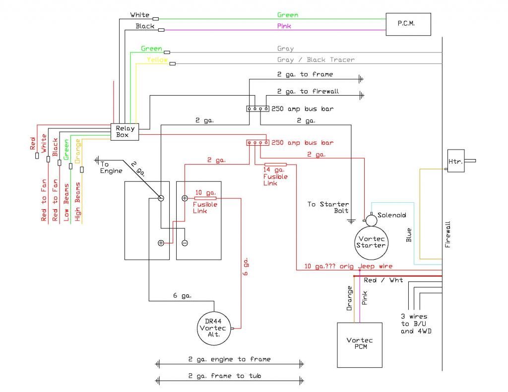
I am comfortable with the majority of the wiring after reading numerous posts on this site and others, but the alternator wiring and fusible link locations have me puzzled. It is a DR44 alternator that puts out 145 amps at full draw is my understanding. I realize it won't be putting out near that much for the majority of its life, but I didn't know if I should be upsizing the wiring for safety sake. I have read a few different posts about locations of the fusible links on different sites and would like your input on those as well. As of right now, I have 6 ga welding cable that should carry approximately 65 amps and a 10 ga fusible link figured into the line. Is it possible to double up the lines and fusible links and run them in parallel to get closer to the 145 amps or is that even needed or possible? I didn't know if the old saying of "rather have it and not need it" then "need it and not have it" counts on something like this.
All of the heavy cable in the Jeep is welding cable. I will have dual batteries, a winch and a mild amp in the Jeep when I finish if that makes a difference. Also, if you see any other grounds that I may need, please speak up. Also just noticed that the bus bars say 250 amp when it should be 350 amp. Any critique of my diagram is welcomed as I am really trying to understand all of this. Thanks for any help and everyone have a safe 4th.
Brad

I am comfortable with the majority of the wiring after reading numerous posts on this site and others, but the alternator wiring and fusible link locations have me puzzled. It is a DR44 alternator that puts out 145 amps at full draw is my understanding. I realize it won't be putting out near that much for the majority of its life, but I didn't know if I should be upsizing the wiring for safety sake. I have read a few different posts about locations of the fusible links on different sites and would like your input on those as well. As of right now, I have 6 ga welding cable that should carry approximately 65 amps and a 10 ga fusible link figured into the line. Is it possible to double up the lines and fusible links and run them in parallel to get closer to the 145 amps or is that even needed or possible? I didn't know if the old saying of "rather have it and not need it" then "need it and not have it" counts on something like this.
All of the heavy cable in the Jeep is welding cable. I will have dual batteries, a winch and a mild amp in the Jeep when I finish if that makes a difference. Also, if you see any other grounds that I may need, please speak up. Also just noticed that the bus bars say 250 amp when it should be 350 amp. Any critique of my diagram is welcomed as I am really trying to understand all of this. Thanks for any help and everyone have a safe 4th.
Brad


Alternator output can go directly to the solenoid and the other two wires go to pins 14 and 15 I think. This alternator is run by the ECU but if you leave the two wires off it will "fail" to 13.8 volts. Other option is to have an automotive electrical shop convert the alternator to a "one wire" that is not run by the ECU. May have some overkill with the size of wire used but that's better than not enough mil. Going in a Jeep I assume you will not have a big stereo and air which will draw lots of power. Biggest draw will be cooling fans.

Thread Starter
Teching In
Joined: Jan 2011
Posts: 5
Likes: 0
From: Sugar Land, TX
Guys,
Thanks for the reply. I didn't show the 2 wires to the PCM or the wires that go to the negative wire sensor. Sorry about that. I was more worried about the bigger charging wires. Specifically the alternator charging wire. The original wire was what looked like a 4 ga with a 8 ga fusible link that jumped between the alternator and a bracket on the side of the alternator. I can't find any 8 ga fusible link, so what do you think of running 2 6 ga welding cables with each of them protected by a 10 ga fusible link. Thanks again and sorry for not labeling the PCM wires.
Brad
Thanks for the reply. I didn't show the 2 wires to the PCM or the wires that go to the negative wire sensor. Sorry about that. I was more worried about the bigger charging wires. Specifically the alternator charging wire. The original wire was what looked like a 4 ga with a 8 ga fusible link that jumped between the alternator and a bracket on the side of the alternator. I can't find any 8 ga fusible link, so what do you think of running 2 6 ga welding cables with each of them protected by a 10 ga fusible link. Thanks again and sorry for not labeling the PCM wires.
Brad
As I said earlier you may have mil overkill. For alternator output I use 8 gauge wire that I get on line used for stereos. It's fine muli-strand wire that will do the job. I do not use fusible links on this wire.