When you click on links to various merchants on this site and make a purchase, this can result in this site earning a commission. Affiliate programs and affiliations include, but are not limited to, the eBay Partner Network.
Hi!
Some greetings from Norway!
After finishing the swap it`s time for sharing some experience here on this forum as a thanks to all the threads and persons that have helped me to make this happen!
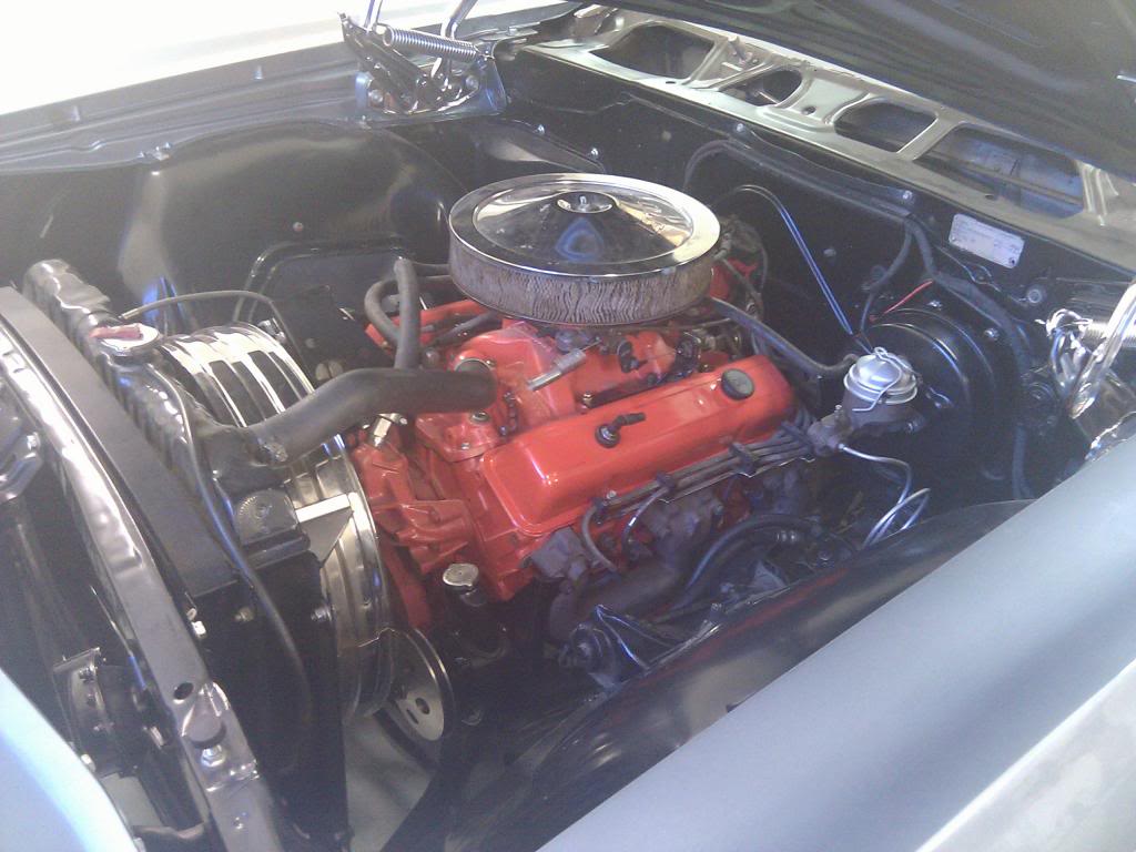
For a while I thought about swapping a LS engine into my 65 Super Sport.
Reading on several forums have proven that this have been done several times before, so about a year ago I took out the 350/TH700R4 that was installed in my car, and sold it.
The primary goal of this project was to manage the complete swap myself, and keep cost at a reasonable level.
After a lot of searching a decision was taken, so from a salvage yard I bought a complete dropout from a 2003 RWD Tahoe Flex-fuel with 90K on the odo.
It included a 5,3L engine/4L60E trans with complete wiring harness, fuse box, throttle pedal, intake pipes and fuel pump (intank type)
After the research I knew I had to get myself a new oil pan, ls1 intake manifold and an exhaust manifold (driver side) from a Trailblazer.
So a new Holley 302-1 GM LS retrofit pan, a used LS1 intake from a 99 Camaro, and a driver side exhaust manifold from a 05 Trailblazer was acquired.
These were assembled with new gaskets, and the engine/trans. was hoisted into place with an elephant crane. I had to make myself a couple of adaptor plates between the engine block and the engine mounts to get the engine in proper position. Plates were made of 10 mm steel.
The transmission mount fit perfect without any modifications. That was because of the TH700R4 swap that I did some years ago. I did move the cross member backwards about an inch or so.
The propeller shaft was shortened a bit to fit.
A new 2,5� dual exhaust system was built and adapted together with the front pipes that included O2 sensors .
Now with the engine/trans bolted up perfect, it was time to modify the front accessories:
-With the lower intake manifold, the outlet waterneck on the waterpump was making interference with the throttle body, so I had to block the upper outlet and make a new one facing forward.
-The generator bracket was also making interference with the throttle body, so it was shaved a bit, and the idler wheel was moved from the waterpump location over to the generator bracket.
- With the LS1 intake, the throttle body will almost touch the top of the waterpump, so I grinded a bit to make some space.
A new front accessories belt was acquired. Optibelt RB 6PK 2620 fit perfect with the new location of idler wheel.
The fan was removed from waterpump, and 2 pc. el.fans was placed behind the aluminium radiator.
Silicone hoses and steel pipes were modified to fit between engine and radiator, so was also cold air intake.
So far so good.
Time for fuel system!!
The stock fuel tank was replaced with a new one from TanksInc. This is bolt-on with built-in fuel pump and fuel gauge sender.
The fuel-filter was mounted right in front of the new tank
On the intake I had to make some small brackets to make the flex-fuel injector rails fit.
So to the wiring system:
This was the most time consuming part for sure
I decided to include the existing wiring through the attached Tahoe fuse box. It means that I had to find available fuse circuits that could take lights, turn signals, horn, wipers, fan and so on.
First of all I found a location for the ECM behind the instrument panel and made some new brackets.
The fuse box was mounted right beside the brake release lever, and the TCM module right above.
The fuse box was mounted as it was on the Tahoe, in other words it can be tilted down to get access to the fuses.
The stock throttle pedal was removed and the one from the Tahoe was modified to fit about at the same location. With this location it wasen`t necessary to modify the wiring harness between the Throttle pedal and the TCM module. Just plug in!!
Next step was to modify the wiring harness to fit my application.
All wires that was connected to sensors/equipment that I didn`t intend to use was removed.
Wiring harness was then placed into the vehicle and each wire was adapted to fit each proper sensor/connector.
4 relays and a separate fuse box were mounted behind the left headlights. These supplies power to high and low beam, and the two cooling fans.
An ODBll connector was mounted under on the left side under the dash panel.
Gauges from Dakota Digital was mounted and connected to the wire harness
Before firing up this thing I had to reprogram the ECU (computer)
A new version og HP Tuners was ordered and after a lot of hours of reading on forums, I was able to flash a new program into the ECM without VATS, EGR and rear O2 sensors.The 2 electric cooling fans is activated by the ecm at two different temps.
Some modifications on the VE table and MAF table was necessary due the change of intake manifold, so after this was done and the speedometer was configurated it fires straight up!!
Still need to do some fine tuning, but overall it runs very good!!
I will make some changes to the fuel system this coming winter. The plan is to integrate the fuelpump reservoir into the stock tank on one way or another.
Will also make som modifications on the fuel rails to make some covers fit over the heads/intake.
Hope this information can be helpful for others that intend to do anything similar.
Like I said I`m very thankful for this and other forums that have helped me alot during this project.
Last edited by bjornas; May 30, 2019 at 03:58 AM.
Reason: Updates
These days I'm finishing the modified wiring diagram in CAD format. Nice to have this updated as long as the whole wiring systems goes through the Tahoe fuse box
When I'm finish I could post it in PDF format here at this forum if it is of interest
These days I'm finishing the modified wiring diagram in CAD format. Nice to have this updated as long as the whole wiring systems goes through the Tahoe fuse box
When I'm finish I could post it in PDF format here at this forum if it is of interest
Sounds like a good idea to me! It never hurts to have more resources/references, especially when it comes to wiring...
Looks nice. I really love the 65/66 Impaled. Especially the Verts. If you ever go for more power you might want to increase the 5/16. Fuel supply line to. 3/8. I like the surge tank idea to make the fuel system more buget friendly.
6 Common C5 Corvette Failures and What's Involved In Repairing Them
Slideshow: From wobbling harmonic balancers to failed EBCMs, these are the issues that define long-term C5 ownership and what repairs typically involve.
Retro Modern Bandit Pontiac Trans AM Comes With Burt Reynolds' Autograph
Slideshow: A modern Camaro transformed into a retro icon, this limited-run "Bandit" build blends nostalgia with brute force in a way few revivals manage.
Top 10 Greatest Cadillac V Series Performance Models Ever, Ranked
Slideshow: Cadillac didn't just crash the high-performance luxury vehicle party, it showed up loud, supercharged, and occasionally a little unhinged...
Coachbuilt N2A Anteros Is an LS2-Powered C6 Corvette In Italian Clothes
Slideshow: A one-off sports car that looks like a vintage Italian exotic-but hides a C6 Corvette underneath-just sold for the price of a new mid-engine Corvette.


 It never hurts to have more resources/references, especially when it comes to wiring...


 Looks nice. I really love the 65/66 Impaled. Especially the Verts. If you ever go for more power you might want to increase the 5/16. Fuel supply line to. 3/8. I like the surge tank idea to make the fuel system more buget friendly.


