When you click on links to various merchants on this site and make a purchase, this can result in this site earning a commission. Affiliate programs and affiliations include, but are not limited to, the eBay Partner Network.
Be warned the plastic clips come apart and dump gas everywhere
Do a lot of people have that issue with these fittings? I guess I haven�t seen that yet in my research. Which ones would you suggest otherwise? Or are you saying in the event of service they come apart and spill gas everywhere?
Or are you saying in the event of service they come apart and spill gas everywhere?
They have been known to blow apart while the engine is running and spray fuel all over the hot engine. The plastic part doesn't fit the aluminum fitting as well as the plastic fitting they were designed for.. There have been known fires from them.
Be warned the plastic clips come apart and dump gas everywhere
Originally Posted by 79LS1FOX
The thread on ones are best...
PART#751166ERL 3/8 to -6
PART# 751156ERL 5/16 to -6
there are others but this is what I use.
Originally Posted by NCDEERE
I used the Summit version of the screw on fittings. Safe and still easy to remove when needed.
Originally Posted by ls1nova71
They have been known to blow apart while the engine is running and spray fuel all over the hot engine. The plastic part doesn't fit the aluminum fitting as well as the plastic fitting they were designed for.. There have been known fires from them.
Everyone, thanks for the warnings and information on the part numbers for the better screw on style fittings. I have processed a return for my plastic clip-on style and the screw on style are arriving today to replace them. For only a few dollars more, I'd rather have a more robust attachment to the fuel rails and the filter/regulator, especially with the potential for spraying gas on hot exhaust.
I have the plastic one, then upgraded to the screw one from Edelbrock, then upgrades to the areoqupp/EARLS (I forget which one) one that pop in and have a retainer clip that�s chained to the fitting. I was afraid the threads(Edelbrock) would gal up on me
Been a while since the last update - I'm waiting on a few parts to come in for the engine and trans, but when they do, it's pretty much going to be full speed ahead.
4L80 updates:
Pump - I sent it out to CK Performance for inspection / rebuild since I wasn't comfortable with the gear pocket and stator half surface finish. Sure enough, it was borderline so I'm having him rework a pump for me.
Valve Body - I completely disassembled the valve body for cleaning and re-assembly. When this trans was rebuilt previously, it's like they did half of the HD2 kit upgrades, but didn't do the dual feed or pump mods. The valve body had been upgraded with the o-ring plugs and valve body filter plug. Other than that, I didn't find any surprises there. I did discover the incorrect separator plate had been sent, but they are sending me the correct one.
Clutch hubs - I have been working on blue-printing my clutch hub assemblies for clutch pack clearance, and I have gotten through the direct and over-run. The direct has 6 face grooved red clutches and 5 of the 0.090" thick Kolene steels and 1 of the thinner 0.060" Kolene steels. This resulted in clutch pack clearance of right at 0.040" which is on the tight end of the spec. With using 6 of the 0.090" steels, I could not get the snap ring installed. This additional clutch and steel are accomodated by using the CK performance kit which includes a new spring retainer and piston.
For the over-run clutch hub, it has 3 Kolene steels and 3 red clutches, so doing the math on the 0.006-0.010" clearance per clutch, it comes out to 0.018-0.030" clearance. This landed right in the middle at 0.025" without doing anything.
Electrical:
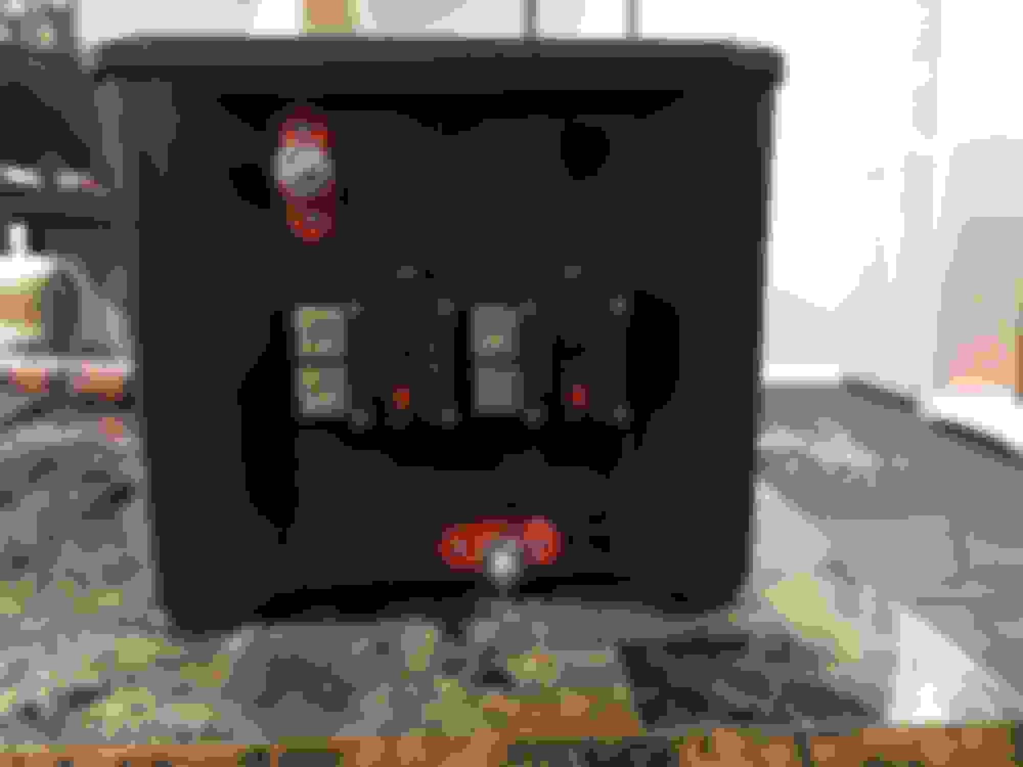
I started working on the layout for my battery box and circuit breakers and going off of the space available in the car, I decided to put the breakers on the short side of the box. The Morosso box is actually really nice to work with so far and seems to be pretty good quality for an aftermarket molded plastic piece.
Lastly, I assembled my other 799 head with the new valve springs and valve seals that came in my gasket kit. I went with a full engine gasket kit that would fit a 2007 TBSS so I could get the right head gaskets, the larger TB gasket, front and rear cover gaskets as well as front and rear main seals. The fel-pro kit I went with (FEL-260-3167) got me all these for pretty close to what it was going to cost to piece them together.
Engine harness is getting close to being done, so hopefully will be picking that up soon. Rotating assembly is going on the balance machine today at the machine shop.
Working on creating a rough wiring schematic for my PCM & fuse box to be integrated with my chassis harness, I am wanting the PCM to have some level input from/to the AC system. I currently have a Vintage Air system with the Gen II compac unit that has 2 relays. I had a binary switch, but might need to go to the trinary switch. There's lots of info out there on this subject, but most people say to forget PCM integration with AC and just wire everything standalone and hope the PCM can compensate for the additional load when the Compressor Clutch engages and the fans come on. I want my install to be a little smarter than that and have the PCM at least know that the compressor clutch has engaged. That seems simple enough to do, I would just interrupt the +12V signal from the Vintage Air to the Compressor clutch and pin it into pin 17 on the red C2 connector. If I wanted the PCM to physically command the compressor clutch on/off for things like high speed / WOT, I could run pin 43 on C2 directly to the ground side of the compressor clutch relay. So far so good right? Here's my proposed wiring schematic:
We don't have any high or low pressure protection yet though, so that needs to be taken into consideration as well. The factory 99-02 trucks used some sort of pressure switches on the low side and apparently one on the high side too, but these trucks had mechanical fans where I am running electric fans. Pins 11 and 55 are for the high and low pressure switches, but I'm not sure how the truck PCM would use that ground signal. Would it just cut the compressor and fans if the AC high side switch tripped? The low pressure switch I can either run to ground so it has signal all the time or figure out what part number switch to use and where to put in on my low side to have some anti-icing protection built in to the system that would cut the compressor clutch when low side pressure drops below the set point.
I did pick up my harness from Swap Specialties earlier this week, and it is a really nice piece from what I have seen so far. Everything on it is new with the exception of a few connectors. All the wiring though is new. It has the correct EV6 injector plugs for my 50lb/hr injectors, they repined my MAF connector for the LS3/7 card style MAF, the fuse box has outputs for 2 fans and a fuel pump, and they even integrated 2 pass through wires for my oil pressure and coolant temp sensors. A tach signal wire and speedometer wire are also included. MAP sensor placement was also addressed for the TBSS intake manifold with the forward position MAP.
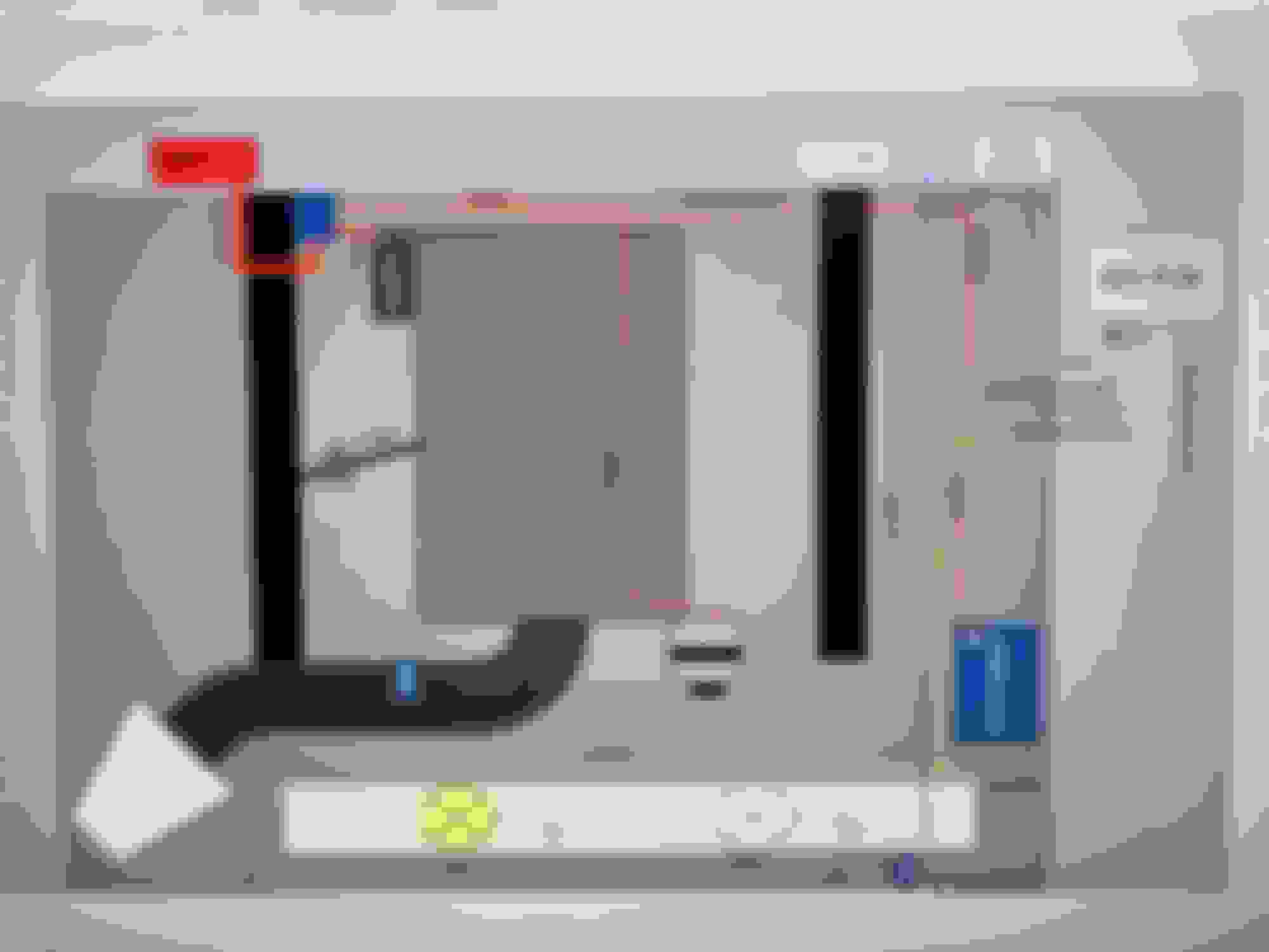
I think I have found a way to mount my PCM on the driver side firewall near under the fender. It is going to require me to mount the PCM at an angle, but no big deal there since I have to provide a place for the PCM bracket to bolt to anyways. Here's my mockup in position using some scrap aluminum 1" flat stock I had laying around:
Still need to figure out my heater hose configuration though. For some reason I'm having a really hard time finding the right combination of parts to clear my upper control arm. a 45 degree -10AN fitting will not clear in the rear port, so I ordered a 90 degree to see if that will clear. I'd like to have AN fittings in this location for a cleaner look, but might have to go the cheaper route of using a street elbow or 2. I think it might be the setback I have on my engine. It's back about as far as I can put it without getting into the firewall - I have about 1/2inch of clearance from the cylinder head to the firewall on the passenger side which is similar to what the Gen 1 SBC had. Don't mind the AC lines, I was trying to mock up something there as well to give me an idea of what I would need, and I think a couple of 90's there will work out well too. worst case I have to buy a 12" section of #8 and #10 AC hardline and bend it up to clear the heater hoses. The rear #8 hardline is from my previous setup and was really just for kicks. The service ports will have to be relocated as they are not serviceable in the spots shown in the below picture.
I wired my AC stand alone but the engine would die occasionally when stopping for alight. I went back through the PCM and its all good now. Much better drivability.
I wired my AC stand alone but the engine would die occasionally when stopping for alight. I went back through the PCM and its all good now. Much better drivability.
What did you end up using for the pressure switches? I tried finding it in your thread, but I didn�t see what exactly you had used. I saw the wiring portion and that helped out quite a bit. But are you just using a pressure switch mounted on the drier? If so, do you have a part number for it?
Vintage Air A/C Wiring with 411 PCM and Gen 4 Rods and Pistons on Gen 3 Crank
Some small changes are being made to my wiring schematic for the A/C wiring to hopefully take advantage of some things built in to the PCM that could control my cooling fan for AC. The way I see if I have 2 options of how to wire the AC into the PCM, and I think Option 2 is how I will do it since the condenser doesn't really need airflow if the compressor is not pumping refrigerant through it. The main difference between option 1 and 2 is how the VA Trinary switch is wired in for high / low pressure protection.
OPTION 1:
+12V A/C request from VA -> goes to Pin 17 (PCM will know A/C is being requested)
PCM Pin 43 (A/C Clutch Ground) -> VA Trinary Switch compressor High/Low cutoff -> A/C Clutch relay ground (this way only allows the compressor to engage when the pressures are in range >30psi or <406psi to complete the circuit)
PCM Pin 55 (low pressure switch) -> ground (essentially this is covered by the VA Trinary switch, since it does both high and low pressure)
PCM Pin 11 (A/C recirc. door) -> VA Trinary switch fan control -> ground (this ground circuit closes when internal pressures >254psi. In theory, this should control fan #2 since my PCM has fan #2 set to recirc. in the tune).
Hopefully this will allow the compressor clutch to cycle with internal pressures, while allowing Fan #2 to cycle on and off when the pressure exceeds or falls below the 254psi threshold. One thing I'm not sure of though, is if the PCM is still seeing the AC request signal and the compressor clutch kicks off, I think my idle will go way out of range because it is in the A/C on idle table. The load would drop off
OPTION 2:
+12V A/C request from VA -> VA Trinary switch compressor High/Low cutoff -> Pin 17 (PCM will know A/C clutch is engaged/disengaged, and will only complete the circuit if pressure is in the range of 30-406psi. Outside that range, the switch will break the connection)
PCM Pin 43 (A/C Clutch Ground) -> A/C Clutch relay ground (clutch relay only gets sent a ground signal when Trinary switch is closed)
PCM Pin 55 (low pressure switch) -> ground (essentially this is covered by the VA Trinary switch, since it does both high and low pressure)
PCM Pin 11 (A/C recirc. door) -> VA Trinary switch fan control -> ground (this ground circuit closes when internal pressures >254psi. In theory, this should control fan #2 since my PCM has fan #2 set to recirc. in the tune).
Another update on the rotating assembly. I am changing to the Gen 4 rods and Flat Top pistons and since they are heavier than the Gen 3 rods and Dished pistons, I wanted the balance checked and it was out 50grams on the front and 50 grams on the rear. Just FYI to anyone thinking about putting Gen 4 rods and pistons on their Gen 3 crank - most likely it will need to be balanced. If I could have found an LQ9 crankshaft it probably would have been cheaper, but this way I know it is all matched, crank is polished, wrist pins are polished, all pistons were mic'd and came out to 0.0020-0.0022 clearance to the bore (had to replace 2 that were out of spec - they were scuffed on the skirts and had a high clearance of 0.0035-0.0040)
Future search terms: Vintage Air 411 PCM ECM Computer Control Wiring Trinary Switch Recirc Door Fan #2 AC A/C compressor clutch
Gen 4 IV Rods Flat Top Pistons LS2 LQ9 on Gen 3 III crank crankshaft balance balancing rotating assembly
Finally got some time in the garage to button up the 4L80e build. For being the first 4L80 I have been into, it wasn't really that challenging for me at least and I had a lot of fun building it. I would definitely do another at some point if the opportunity presents itself. I had to disassemble and reassemble it several times checking and rechecking clearances and endplay, but in the end I think I have a pretty good setup now.
Here's how my clearances worked out on what I was able to measure / adjust:
rear section endplay: 0.007"
front section endplay with rear loaded: 0.005"
front section endplay with rear not loaded: 0.012"
output shaft endplay: 0.005"
More info on the build for future reference:
no wave plates
internal dual feed mod
accumulator delete (CK performance)
CK Performance pump
bleed hole in direct clutch housing (to eliminate clutch soft apply at high rpm)
new bushings and seals everywhere
6 clutch direct
air checked everything I could
On to some pictures:
Reverse band servo installed and torqued down
Check ***** installed. Note no check ***** for the accumulators since they are deleted:
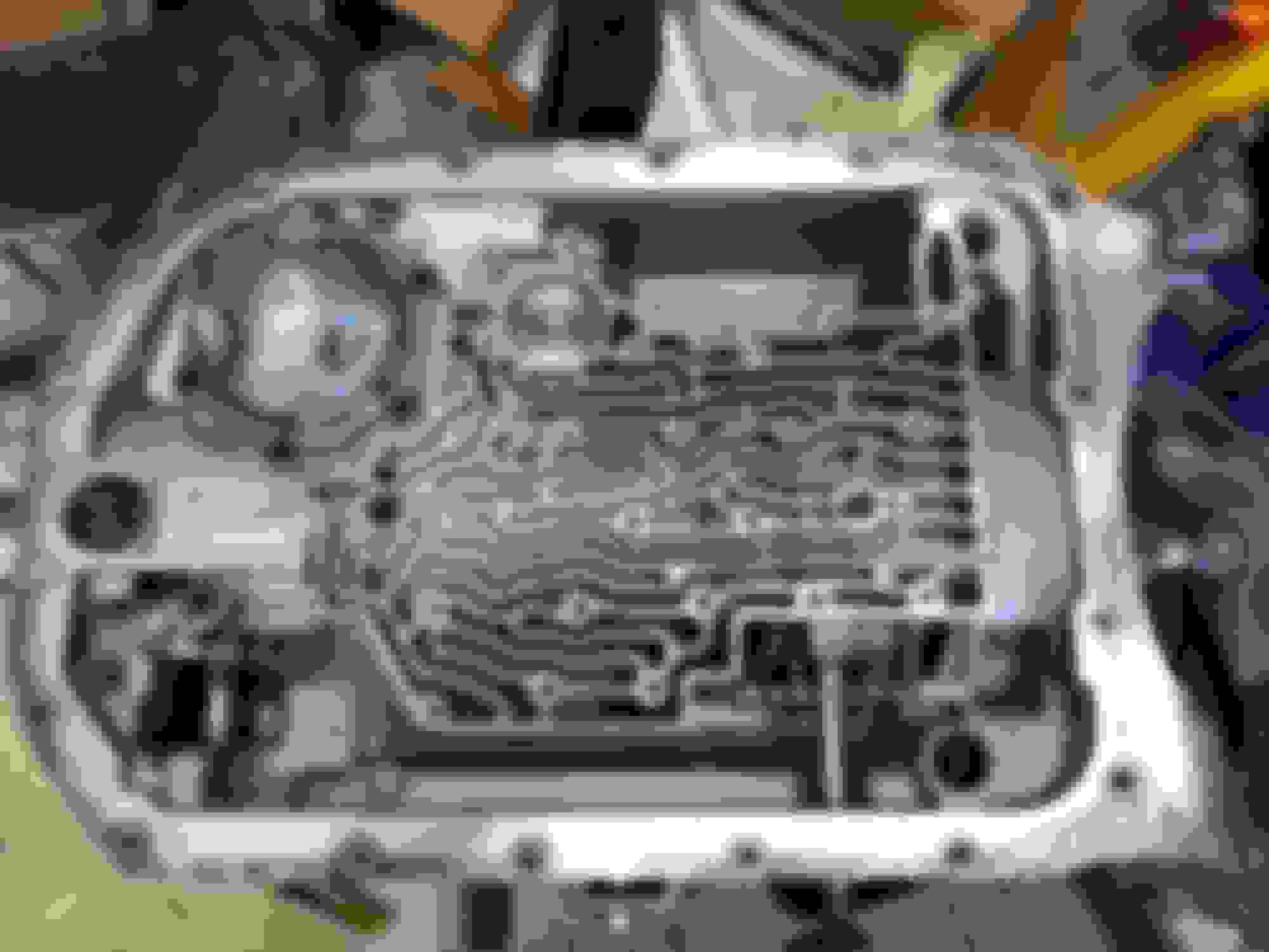
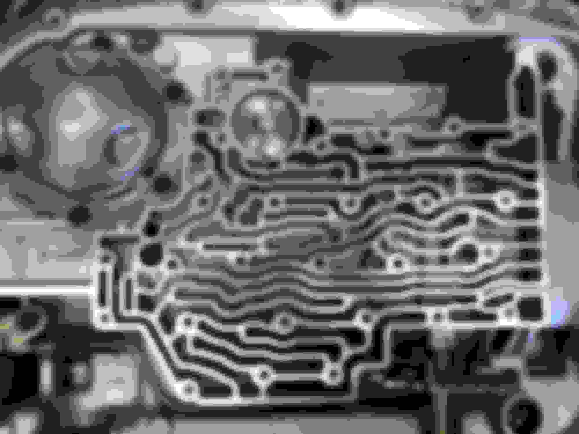
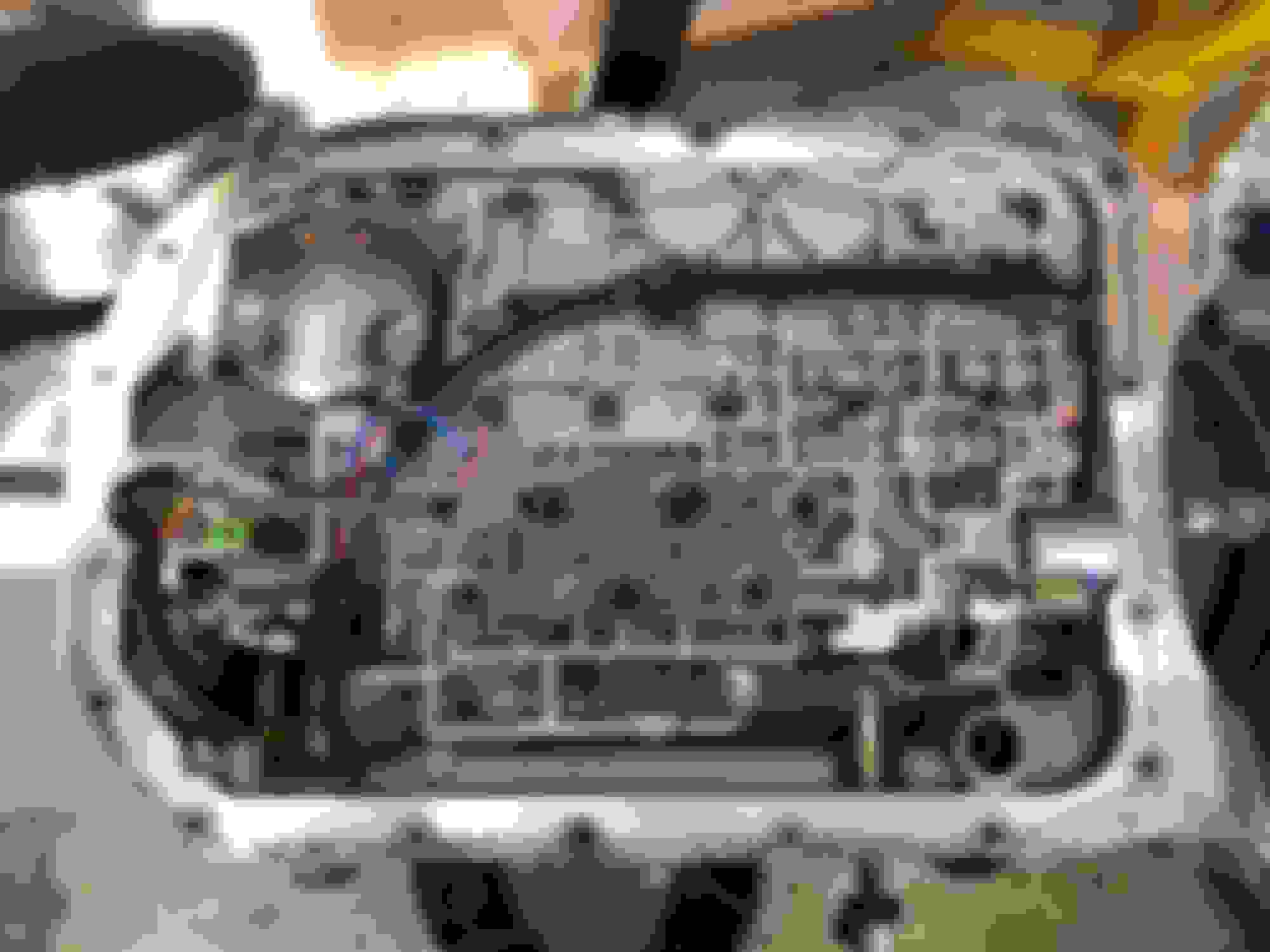
Valve body bolted down, all bolts torqued to 118in-lbs. New rostra harness installed. It was really tough to push through the hole so hopefully that means that the o-ring will seal well.
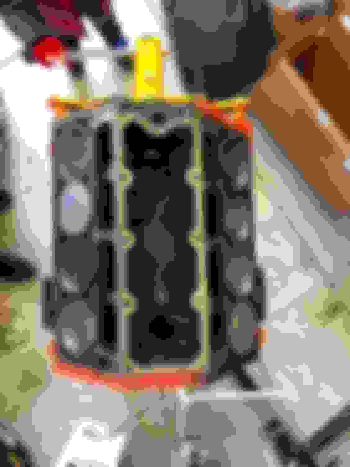
Tailshaft housing mocked up for photo-op. In this pic you can see my marks on the bell housing ears for where I need to trim to fit the headers. Now I've got one heck of a mess to clean up, lol.
Hopefully in the next few days I will be pulling the block and mockup up trans out of the car to start on the 6.0 build.
Got the engine pulled from the car and started on the build about 2 weeks back. Everything has checked out so far, only had a small snafu on the rear cam bearing - there was a ridge all the way around that would not allow the cam to slide in all the way. Other than that, everything has been fairly straightforward and quite smooth for my first LS build. I can now see why people do not like the cheap angle gauges with the dial - way too difficult to get it to stay still without moving. I'm guessing my accuracy to the gauge is +/-2degrees in addition to whatever tolerance it has itself due to this movement.
Crankshaft in and torqued down
All pistons in, rod bolts torqued with my helper holding it from "falling" as he said.
Camshaft installed, new thrust plate torqued, LS2 style damper, new LS2 timing chain, and new Melling oil pump.
The oil pickup needed to be modified to reach the main stud, and then I had to cut out a section of the oil baffle to clear it. I am using an LS1 baffle with this TSP (Top Street Performance) oil pan. I also cleaned up the factory balancer and put a coat of paint on it to make it look a little better. Wishing now that I would have painted the front cover an aluminum color, but I don't want to take it back off just for that since it will be largely hidden behind the water pump, accessory brackets and Intake tube.
Late yesterday my new LS7 lifters showed up and I was able to measure for pushrods and came up with 7.425" to land me right at 0.080" preload on the LS7 lifters. Going with chromoly 5/16 diameter pushrods for more RPM protection.
Lastly, I had to buy different piston rings. The ones I got were not correct for the LS2 pistons. The E972K had a 1.5, 1.5, 3.0mm pack. The LS2 pistons need a 1.2, 1.5, 2.5mm ring pack, so I was quite frustrated while trying to assemble them and having to drop another $100+ on a new ring pack. The correct ring pack for the LS2/LQ9 pistons is E979K.
Then engine quickly went from just a short block to the complete package - oil pan to intake manifold. This engine was almost easier to assemble (to me at least) than the GEN 1 SBC I built several times. I knew I was going to have some difficulty finding the right length serpentine belt as I was mixing and matching accessory drives and I did an idler pulley re-location. I measured the length with the tensioner at about mid travel and came up with 82" but that ended up being way too short. Next I tried 83.5" and that didn't even engage the tensioner!. Finally landed on an 82.5" belt that put the tensioner right at the middle of the adjustment window. Gates K060825 is what I landed on for the main serpentine belt using the L99 pump & tensioner, the truck accessory bracket with 145amp alternator and the ICT billet idler relocation bracket.
Hopefully in another month or so. My tank is on backorder, so that will most likely be the limiting factor as I�m getting ready to drop the engine in for next weekend. Hopefully engine and trans will be installed and I can start on the AC plumbing, heater hose plumbing, and planning out my cold air intake box / shield. I did a little re-work to my harness to incorporate a few more engine wires and added some pins for AC control and I�m planning to run my wideband through the pcm via the EGR pintle position pin which is a 0-5V signal.
I ended up going with a TanksInc setup on the recommendation of a bunch of my co-workers that have used it. Not going to be doing auto-crossing, road racing, or things like that - just a nice cruiser. I've heard that if you do auto crossing or road racing with the Tanks stuff, you can get into fuel starvation issues at low fuel levels.
On to some progress updates. I got the engine and trans bolted in the car over the weekend. My parents came over and my dad helped me drop the engine and trans in - we decided to put them in together as a unit to avoid having to slide the heavy 4L80 under the car and then heave-ho it up onto my sketchy-home-made trans jack.
I wanted to mock up as much as I could on the engine before dropping it in, and I had a few things to button up before it could be installed too. I drilled and tapped my L99 water pump for the steam vent in a similar location that the Holley mid-mount pump is to give a cleaner look. My pump was already customized on the heater hose side anyways, so if I ever need to get a new pump, I'm going to be doing some work for that as well.
Here you can see my solution to the heater hose outlets being too close to the upper control arm. I used a combination of 90deg NPT fittings and 45 degree NPT to -10AN. I need to slightly tweak the rear fitting to more closely follow the line that the front one takes, but this gives an idea of what I was going for. Also, you can see my weather pack connector for the AC clutch wire that I integrated into my engine harness. All in I must have added 10+ wires to this harness, but it was well worth it.
For my in dash temp gauge, I needed an attometer sending unit placed in the head, so I drilled out the plugged hole to 9/16 and tapped it for 3/8 NPT.
For my alternator, I integrated a 6AWG wire from my painless high amp charging kit into my engine harness that will go to my 200amp fuse on the firewall and feed power to the engine & chassis harnesses. I also tested out the routing of the injector harness between the rails and the manifold, and I do have enough wire length to make it work for hiding the wires.
Here, we wanted to test fit the engine to the transmission to make sure there was clearance between the headers and the trans bell housing since the ears stick out quite a ways. The driver side cleared by a mile, but the passenger side did need some trimming - basically flush with the starter bump gave a minimum of 1/4" clearance.
Torque converter installed - I had to do it 3 times because I figured there was no way it went on fully the first time since I only got one click. Long story short, I got really lucky and it was actually on all the way. This is a 2800-3200 stall lockup converter. If you follow Bad Luck Garage on YouTube, this is the same converter that is in the DR Nova. In that car which is a similar setup to mine, it foot brakes to about 3200.
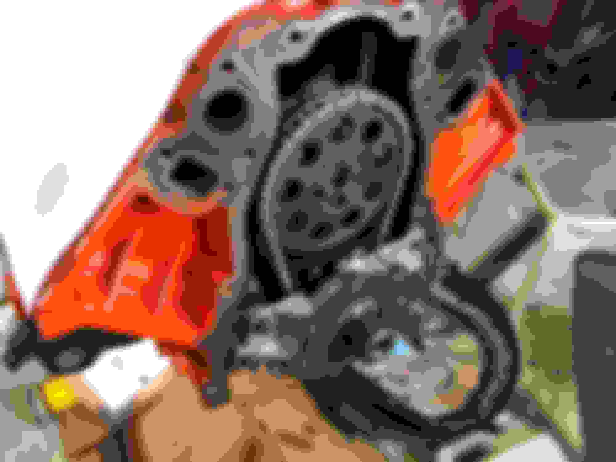
Engine and trans mated together. I am using the factory 2002 Silverado 2500HD dipstick as it fits the tunnel nicely when installed - it's actually closer to the engine / trans than the actual tunnel. However, it has to be installed before the engine/trans go in - otherwise there just isn't room due to the very long end that goes into the trans. Also, if you look closely, you can see the portion of the 4L80 bell housing that was trimmed for header clearance.
Lastly, I thought this was kind of a cool shot. We did end up having to take the AC compressor and bracket off to get the engine to go in, but it only took 30 mins or so of maneuvering to get it on the engine mounts. Much easier this way than doing it separately.
I have more updates than this, but will save that for another post. The engine and trans are in the car, but I didn't take any pics right after it went in.
6 Common C5 Corvette Failures and What's Involved In Repairing Them
Slideshow: From wobbling harmonic balancers to failed EBCMs, these are the issues that define long-term C5 ownership and what repairs typically involve.
Retro Modern Bandit Pontiac Trans AM Comes With Burt Reynolds' Autograph
Slideshow: A modern Camaro transformed into a retro icon, this limited-run "Bandit" build blends nostalgia with brute force in a way few revivals manage.
Top 10 Greatest Cadillac V Series Performance Models Ever, Ranked
Slideshow: Cadillac didn't just crash the high-performance luxury vehicle party, it showed up loud, supercharged, and occasionally a little unhinged...
Coachbuilt N2A Anteros Is an LS2-Powered C6 Corvette In Italian Clothes
Slideshow: A one-off sports car that looks like a vintage Italian exotic-but hides a C6 Corvette underneath-just sold for the price of a new mid-engine Corvette.