

ANOTHER Alternator Question!

Thread Starter
TECH Resident
iTrader: (1)
Joined: Jan 2014
Posts: 897
Likes: 33
From: Colorado Springs, CO
Yes, I know. Another alternator question. There are dozens of threads and questions about this, and seemingly endless answers. This appears to be much more complicated issue than you might think. I have spent hours reading through a variety of threads, on a number of message boards.
I'm installing a stock LS1 into a non-GM car. The drive train came out of a 2001 Firebird. I have an aftermarket ECU to run the engine. And a Painless Wiring basic chassis harness for everything else. I do not want to run the alternator through ECU for a variety of reasons. So I'm using Alternator Exciter wire from the chassis harness.
As I read in a lot of places, I placed a 470 ohm, 1/2 watt resistor in the exciter wire, which cuts the power down to 8.56 volts (engine off). Unfortunately, the brand new alternator will not charge.
So then I started perusing the Painless Wiring tech section. And I came across something not mentioned anywhere else.
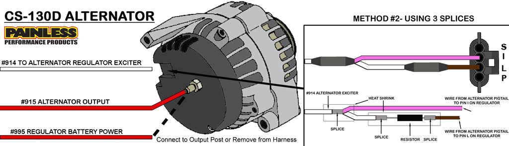
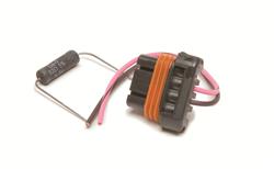
This shows two wires for this alternator - one with the resistor, and one with 12v. Painless also sells an adaptor kit, with the right plug and a 85 ohm 5 watt resistor in it (which can certainly be purchased cheaper), designed to adapt the new alternator to older cars.
So, has anyone used this method? Am I on the right track? Since no one else has mentioned this, am I way off track?
I'm installing a stock LS1 into a non-GM car. The drive train came out of a 2001 Firebird. I have an aftermarket ECU to run the engine. And a Painless Wiring basic chassis harness for everything else. I do not want to run the alternator through ECU for a variety of reasons. So I'm using Alternator Exciter wire from the chassis harness.
As I read in a lot of places, I placed a 470 ohm, 1/2 watt resistor in the exciter wire, which cuts the power down to 8.56 volts (engine off). Unfortunately, the brand new alternator will not charge.
So then I started perusing the Painless Wiring tech section. And I came across something not mentioned anywhere else.

This shows two wires for this alternator - one with the resistor, and one with 12v. Painless also sells an adaptor kit, with the right plug and a 85 ohm 5 watt resistor in it (which can certainly be purchased cheaper), designed to adapt the new alternator to older cars.
So, has anyone used this method? Am I on the right track? Since no one else has mentioned this, am I way off track?
Thread Starter
TECH Resident
iTrader: (1)
Joined: Jan 2014
Posts: 897
Likes: 33
From: Colorado Springs, CO
Interesting. I spent a lot of time looking for information before I posted this. I read dozens of posts on multiple forums. You're the first one that presented information like this. Image #6 appears to follow the diagram that I got from Painless Wiring. I'm going to pick up a new plug and a resistor, and wire it like you and PW recommend. Thanx for your help. I'll let you know how it works out.
Thread Starter
TECH Resident
iTrader: (1)
Joined: Jan 2014
Posts: 897
Likes: 33
From: Colorado Springs, CO
OK, it's fixed. This is the Real Answer.
The F-body LS1 uses a single wire alternator. This single wire is connected to the ECU, which controls the charging rate. The charging rate is controlled by a program that varies the charge depending on things like temperature, engine load, throttle position, etc. Mostly an attempt to gain more fuel mileage.
If you install the LS1 along with the stock ECU and wiring harness, just plug everything in and don't sweat it.
But if you're using an aftermarket ECU or a carb, then you'll need to use a 2 wire plug, a resistor, and a diagram similar to the one I posted above. Which is essentially the same as Russ's image #6. There are a couple of different ways to accomplish this goal, as Russ shows, but this is the one I found easiest to do. I connected this up this afternoon, and immediately got 14.10v.
Unfortunately, I did not find this information in the instruction book for the Painless Wiring harness.
In previous reading, I found many people who stated to simply place a 470K ohm 1/2 watt resistor in the line, and it would work. But, that didn't work for me; I don't know why.
I am using a Megasquirt MS3+ ECU. I could connect that one wire into the ECU, and it would control it in the same way the stock ECU does. But I was concerned that if the alternator started to fail and got noisy, it could take out the ECU. Maybe that can't happen, and I was worried about nothing. But keeping them separate like that helps me sleep at night.


