07+ E67 BCM Brake Signal Verification


Thread Starter


Joined: Feb 2010
Posts: 907
Likes: 366
From: Champaign, IL
 07+ E67 BCM Brake Signal Verification
 I am looking for someone with an 07+ LS4 to verify the on/off conditions for the brake switch signal between the BCM and the ECM/TCM.

What I need is for someone to verify two conditions on ECM Connector 1 (Blue), Pin 7 (or TCM Pin 42).
When brake pedal is pushed, does it see 12V?
When the brake pedal is released, is it an open circuit or goes it go to ground?
I am not running a BCM for my swap and want to verify that I have C1, Pin 7 wired correctly (12V when brakes applied, Open Circuit when released).
Any help would be greatly appreciated!
What I need is for someone to verify two conditions on ECM Connector 1 (Blue), Pin 7 (or TCM Pin 42).
When brake pedal is pushed, does it see 12V?
When the brake pedal is released, is it an open circuit or goes it go to ground?
I am not running a BCM for my swap and want to verify that I have C1, Pin 7 wired correctly (12V when brakes applied, Open Circuit when released).
Any help would be greatly appreciated!


Hey Guru,
Not anywhere near mine at the moment, but seem to recall its a 5V ref signal from switch to BCM then BCM 12v to lights.
Still cracking at DOD or you run into another issue?
Not anywhere near mine at the moment, but seem to recall its a 5V ref signal from switch to BCM then BCM 12v to lights.
Still cracking at DOD or you run into another issue?


Thread Starter
Joined: Feb 2010
Posts: 907
Likes: 366
From: Champaign, IL
I am more concerned about the output signal coming "from" the BCM "to" the ECM, not the signals between the brake switch sensor and the BCM. I do not have a BCM, so the signal between BCM C5, Pin 6 and ECM C1, Pin 7 & TCM Pin 42 is what I want to replicate (or have tried to replicate), so I would like real confirmation on what the signal is with the brake applied and released.
Many of the outputs from the BCM are 12V signals to activate other chassis functions. But the diagram doesn't specify what the signal is, so I would like to have it verified.
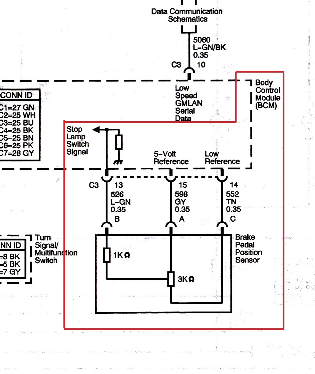
For those interested in the Brake Pedal Position Switch, here is its diagram for how it connects to the BCM. I have confirmed it is a 4K ohm variable resistor so from this diagram the signal back to the BCM should vary be between 5V and 0V.
However, another section of the FSM has this to say... both simply can't be true:

Many of the outputs from the BCM are 12V signals to activate other chassis functions. But the diagram doesn't specify what the signal is, so I would like to have it verified.
For those interested in the Brake Pedal Position Switch, here is its diagram for how it connects to the BCM. I have confirmed it is a 4K ohm variable resistor so from this diagram the signal back to the BCM should vary be between 5V and 0V.
However, another section of the FSM has this to say... both simply can't be true:
Thread Starter
Joined: Feb 2010
Posts: 907
Likes: 366
From: Champaign, IL
One good thing about the move is that my current garage is too small to do work for others, so my focus for the next year will be on my LS4/F40 swap (redoing the interior, better wheel/tire package, revisiting DoD or eliminating it all together, and possibly adding a turbo...).