


Delteq Opti Box from inside pic.
Thread Starter
Teching In
Joined: Jan 2009
Posts: 39
Likes: 0
Since I got ripped off from a guy on the Corvette Forum, he sold me a defect opti box with the complete system. I thought since the box doesn't work I might as well take it apart and see if anyone has some schematics that could help me out. I have a few people on hand, electronic engineers, which might be able to help.
I already have the wiring harness schematics from the Delteq site. Any help would be appreciated and maybe we can get down to fixing these damn opti boxes.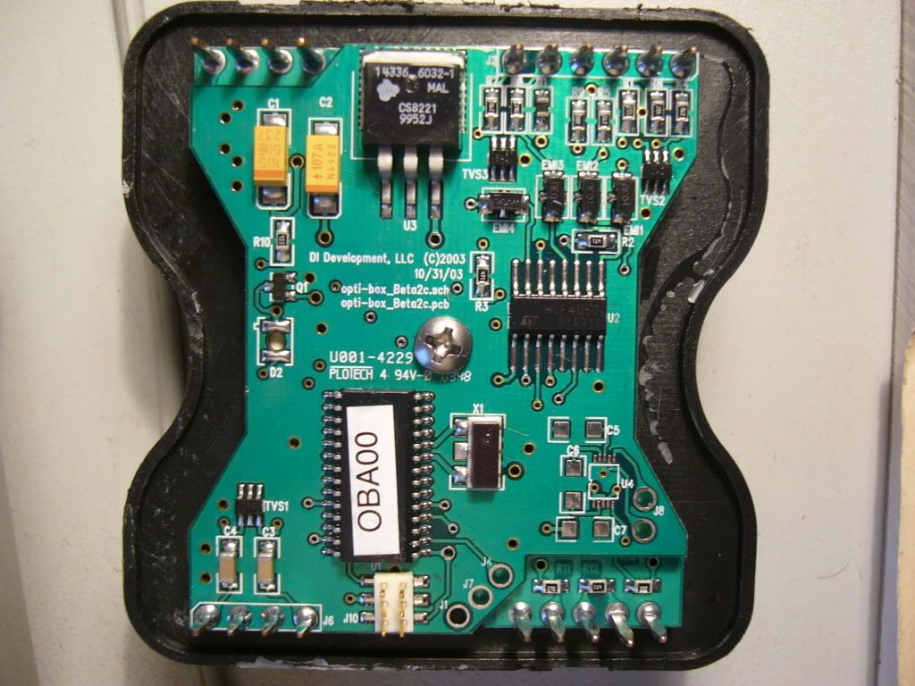
I already have the wiring harness schematics from the Delteq site. Any help would be appreciated and maybe we can get down to fixing these damn opti boxes.
good eye dave but thats a diode lol............D1 is a diode its actually there and in place.......however that output transistor is showing signs of excessive heat see the darker black spot in the middle that looks like its wet?......OP what are the symptoms of the box? also pull out the center screw and check the back of the board for broken/cold solder joints
On The Tree
Joined: Oct 2011
Posts: 179
Likes: 3
From: Eastern Kentucky
however that output transistor is showing signs of excessive heat
The only transistor that I see is Q1 located on the left side between R10 and D2. That big thing with the label on it will probably be some sort of EAPROM that is programmed for a specific sequence of events.
SMD's are fairly easy to remove and troubleshoot. There's not much on there to fail and just wonderin' if you're sure that's the problem. The Delteq site mentions a troubleshooting LED on the board somewhere. Is that D2 mounted to the rear of the board? Have you checked the LED for what it "thinks" is wrong with it? If you could get me the part number off U2 and a pic of the back side of the board I could maybe reverse engineer a schematic for you. Peel the label back off OBA00 and see if there's a number there also.
I need to open me up an electronics repair shop. There's money to be saved and made.
 I've been involved with troubleshooting components at board level most of my life and although I have no formal electronics training, (Other than 50 years of OJT) I rarely get stumped.
Good luck ---Gunny---
I don't really see the "output transistor". The big device at the top/center is a 5 volt regulator. Probably designed to get all the 12 volt signals down to 5 volts that the PCM/ECM can better work with. Anything marked TVS 1,2,3 is only a transient voltage suppressor and they are very low current devices that rarely fail.
The only transistor that I see is Q1 located on the left side between R10 and D2. That big thing with the label on it will probably be some sort of EAPROM that is programmed for a specific sequence of events.
SMD's are fairly easy to remove and troubleshoot. There's not much on there to fail and just wonderin' if you're sure that's the problem. The Delteq site mentions a troubleshooting LED on the board somewhere. Is that D2 mounted to the rear of the board? Have you checked the LED for what it "thinks" is wrong with it? If you could get me the part number off U2 and a pic of the back side of the board I could maybe reverse engineer a schematic for you. Peel the label back off OBA00 and see if there's a number there also.
I need to open me up an electronics repair shop. There's money to be saved and made. I've been involved with troubleshooting components at board level most of my life and although I have no formal electronics training, (Other than 50 years of OJT) I rarely get stumped.
Good luck ---Gunny---
The only transistor that I see is Q1 located on the left side between R10 and D2. That big thing with the label on it will probably be some sort of EAPROM that is programmed for a specific sequence of events.
SMD's are fairly easy to remove and troubleshoot. There's not much on there to fail and just wonderin' if you're sure that's the problem. The Delteq site mentions a troubleshooting LED on the board somewhere. Is that D2 mounted to the rear of the board? Have you checked the LED for what it "thinks" is wrong with it? If you could get me the part number off U2 and a pic of the back side of the board I could maybe reverse engineer a schematic for you. Peel the label back off OBA00 and see if there's a number there also.
I need to open me up an electronics repair shop. There's money to be saved and made.
I've been involved with troubleshooting components at board level most of my life and although I have no formal electronics training, (Other than 50 years of OJT) I rarely get stumped.Good luck ---Gunny---
On The Tree
Joined: Oct 2011
Posts: 179
Likes: 3
From: Eastern Kentucky
im a BSEE but i been doing automation design for the past 4 years
 It happens all the time.....to me also. Familiarity breeds contempt.
Between your engineering experience and my troubleshooting knowledge we should be able to fix this for the OP. Compared to what's required to make a robot work autonomously this should be a walk in the park. If we got together with all the parts, on a test bench with a 12 pack I'm sure it would be no problem. LOL
On The Tree
Joined: Dec 2011
Posts: 109
Likes: 0
From: Kissimmee, Florida
Damn, that suks that you cannot return it, but electronic parts have a "really" small window of return that just about everyone adopts! Hopefully these guys will get u fix'd up in a jiffy...
Trending Topics
This is a great topic! For awhile i was debating about getting a delteq or ltcc but with the lack of customer support with both of them going out of business and there brain boxes going bad i stayed away. Couple really good deals came up but never got to pull the trigger on one. Im sure there will be alot of happy people that if this is the common issue with these boxes and theres a cheap solution they might see a come back and more people using them again.
LS1 Tech Stories
The Best V8 Stories One Small Block at Time

Gas Monkey Built a 6-Wheel Ferrari Testarossa With a Corvette LT4 Engine
Verdad Gallardo
7 Most Reliable High-Performance Engines GM Has Ever Built
Verdad Gallardo
Amazing '71 Camaro Restomod Is Modern Muscle Car Under the Skin
Verdad Gallardo
6 Common C5 Corvette Failures and What's Involved In Repairing Them
Pouria Savadkouei
Retro Modern Bandit Pontiac Trans AM Comes With Burt Reynolds' Autograph
Verdad Gallardo
Top 10 Greatest Cadillac V Series Performance Models Ever, Ranked
Pouria Savadkouei
Top 10 Most Powerful Chevy Trucks Ever Made!

Hennessey's New Supercharged Silverado ZR2 Has 700 HP
Verdad Gallardo
Coachbuilt N2A Anteros Is an LS2-Powered C6 Corvette In Italian Clothes
Verdad Gallardo It happens all the time.....to me also. Familiarity breeds contempt.Between your engineering experience and my troubleshooting knowledge we should be able to fix this for the OP. Compared to what's required to make a robot work autonomously this should be a walk in the park. If we got together with all the parts, on a test bench with a 12 pack I'm sure it would be no problem. LOL
Thread Starter
Teching In
Joined: Jan 2009
Posts: 39
Likes: 0
Thanks guys for trying to help me out and others maybe also. There sure is a lot of money to be made repairing these opti boxes!!!
I already have a Delteq system installed but have misses at WOT, it's a very common failure. This was the reason for me to get a working opti box so I could replace mine. Well, since no one is selling one, I had to buy a complete system. Now I have everything double, inclusive the defect opti box I bought.
The difference to mine is, the engine just wont start with it. When I install my box, the engine starts immediately.
Scroll down the manual to page 15-18 this might help a little. http://www.delteq.com/Manual_r3.pdf
What I did notice was:
LED flashes once when key on
LED flashes properly during key on and cranking
but none of the coils fires
LED won't turn and stay on while cranking like mine does
It can't be the opti spark in case anybody comes to that conclusion. I'm using an almost brand new Dynaspark opti, and with my box the engine runs.
See if I can get more pictures of the back side tomorrow. A friend of mine is looking/testing the hardware at the moment.
Thread Starter
Teching In
Joined: Jan 2009
Posts: 39
Likes: 0
Here are a few answers to your questions.
U2#'s: HCF 4050 // ST 91A317
D2 is the LED
Socket J10 is used for programing
Underneath the label: PIC 18F242-E/50 // 035249G
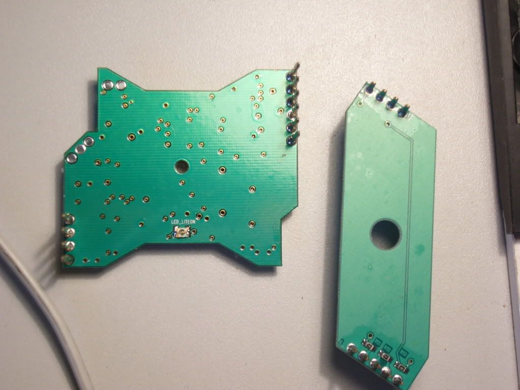
There are no signs of anything unusual. The picture below shows the rear side.
U2#'s: HCF 4050 // ST 91A317
D2 is the LED
Socket J10 is used for programing
Underneath the label: PIC 18F242-E/50 // 035249G
There are no signs of anything unusual. The picture below shows the rear side.

TECH Regular
Joined: Oct 2011
Posts: 407
Likes: 2
From: Keller Tx
Interesting.
I would reflow U3 regulator and fill all through hole points especially the big one by U3. These go through many hot /cold cycles and the eyelets will crack going through the board.
Some larger solder joints will become cold (U3). Doesn't take much time to do this and you will be surprised what might happen.
Good Luck
Thread Starter
Teching In
Joined: Jan 2009
Posts: 39
Likes: 0
Sorry for the delay but because of the holidays and other things I wasn't able to get back to you any sooner. Here is an update on what happened so far.
I opened up my other opti box (fully operative) and found nothing visually being different. My friend compared both boards (actually there are two in each box as seen in the pictures) and found no difference either. He also verified that electronically there is no difference between the larger and smaller boards.
I installed the smaller board into my functioning opti box and the engine started right off. This means, only the bigger board has a defect of some kind and not the smaller board. I think it could be the software but have nobody that can read out the two EEProm's and compare.
It's time that 1963SS and guik95lt1, like you promised, or anyone else go to work and see if they can get this thing working.
Thanks
Arnold

TECH Regular


Joined: Aug 2005
Posts: 430
Likes: 0
Have you had any micro miniature repair guys look at the bigger board and see if something is bad, under operating voltage and temperature?
Board looks good, but it doesnt take much to cause a fault.
Also, the chip itself has to be able to be read somehow, you would think.
Board looks good, but it doesnt take much to cause a fault.
Also, the chip itself has to be able to be read somehow, you would think.
Thread Starter
Teching In
Joined: Jan 2009
Posts: 39
Likes: 0
I have a friend which is an electronic engineer, he compared both boards and found nothing. Since I have no one that can read the EEprom, I think this is the problem, I will never find a solution.
Too bad the fellows that said it wouldn't be a problem to repair never came back to offer their help. I guess they bit off more than they can chew....
Too bad the fellows that said it wouldn't be a problem to repair never came back to offer their help. I guess they bit off more than they can chew....
TECH Regular
Joined: Aug 2005
Posts: 430
Likes: 0
I have a friend which is an electronic engineer, he compared both boards and found nothing. Since I have no one that can read the EEprom, I think this is the problem, I will never find a solution.
Too bad the fellows that said it wouldn't be a problem to repair never came back to offer their help. I guess they bit off more than they can chew....
Too bad the fellows that said it wouldn't be a problem to repair never came back to offer their help. I guess they bit off more than they can chew....

I've got a delteq unit that has worked great for the last few years. I've always been fearful of it's demise.
Been looking at a megasquirt just to force myself to learn the workings and know how to fix a problem.
Been looking at a megasquirt just to force myself to learn the workings and know how to fix a problem.