


stock tachometer not working
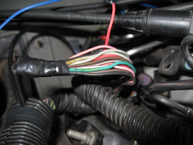
Here is the bundle of wires. There are 12 Total on this bundle of wires. Colors are as follows:
(2) Solid Gray
(2) Solid Black
(2) Solid Red
(1) Solid Green
(1) Solid Brown
(2) Pink w/ Black Stripe
(2) Brown w/ White Stripe
There is another single Solid Red wire on another bundle of wires right behind it. It is sticking up and has electrical tape covering the end.
I know that the (1) Solid Green wire and (1) Solid Black wire go to the A/C connector. That eliminates (2) wires.
Here's the question now. After we determine which wires need to be connected, can I just strip them and solder them together, or will I need the connector pieces?
BLUE PCM CONNECTOR
41
BLACK
EGR Pintle Position. Sensor Ground.
47
GRAY
EGR Pintle Position. Sensor 5V REF
55
BROWN
EGR Pintle Position. Sensor Signal
61
PNK/BLK
Camshaft Position. Sensor Ref. Low
73
BRN/WHT
Camshaft Position. Sensor Signal
RED PCM CONNECTOR
7
RED
EGR Control
39
RED
Camshaft Position. Sensor B+ Supply
41
GRAY
EGR Position Sensor Ground
This info taken from: http://www.ls2.com/boggs/torques/99pinpcm.htm
These (8) wires listed take care of (10) wires with the (2) A/C wires included of the (12) wires. I am still missing the purpose of (1) PINK/BLACK wire and (1) BROWN/WHITE
41
BLACK
EGR Pintle Position. Sensor Ground.
47
GRAY
EGR Pintle Position. Sensor 5V REF
55
BROWN
EGR Pintle Position. Sensor Signal
61
PNK/BLK
Camshaft Position. Sensor Ref. Low
73
BRN/WHT
Camshaft Position. Sensor Signal
RED PCM CONNECTOR
7
RED
EGR Control
39
RED
Camshaft Position. Sensor B+ Supply
41
GRAY
EGR Position Sensor Ground
This info taken from: http://www.ls2.com/boggs/torques/99pinpcm.htm
These (8) wires listed take care of (10) wires with the (2) A/C wires included of the (12) wires. I am still missing the purpose of (1) PINK/BLACK wire and (1) BROWN/WHITE
Last edited by djfury05; Sep 27, 2010 at 06:47 PM.
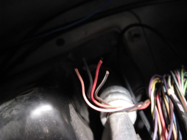
*UPDATE* I have taken apart the wiring harness and traced each wire listed above ^^ back to the PCM. There are 4 wires that do not lead to either the blue or red connector on the PCM, rather behind the intake in another wire loom that I haven't traced.
These are the 4 wires leading back behind the intake. (1) each: Solid Black, Pink/Black, Solid Red, and Brown/White.
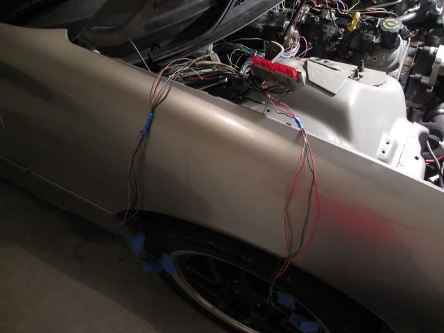
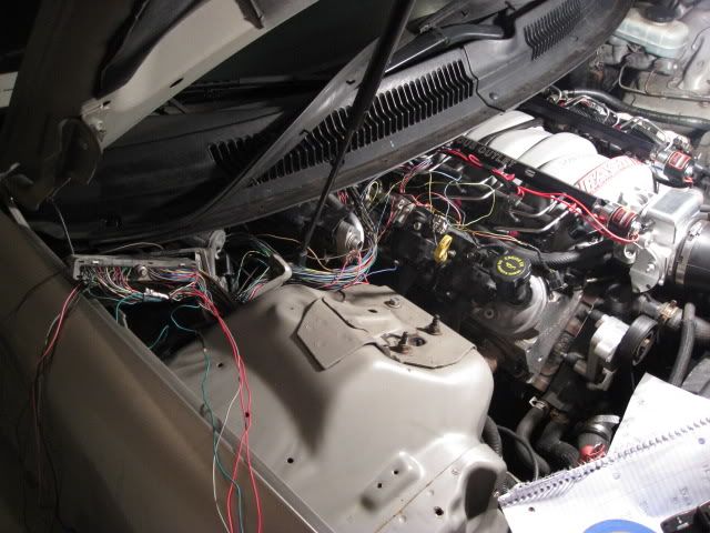
These are the other wires I have already traced.
These are the 4 wires leading back behind the intake. (1) each: Solid Black, Pink/Black, Solid Red, and Brown/White.
These are the other wires I have already traced.
Shoot me a call at my shop tomorrow.I'm pretty sure a customer is dropping off a 00 Z around 10am. On the phone I can atleast tell you the colors.The other side would be the 3-4 wires that don't go back to the pcm. Should be easy enough to figure out.
I believe I've got it figured out.. the 4 wires in back need to be connected to RED 41, 61, 73, and BLUE 39. All the colors correspond and if on original wiring, there were 2 connectors, male/female, this is why there would be extra wires that I can't find where they are going. I am going to splice and try it after I give Slowhawk a call
LS1 Tech Stories
The Best V8 Stories One Small Block at Time

Topdon ONE vs. Artidiag 800 BT2: Which is the Diagnostic Tablet For You?
Pouria Savadkouei
Gas Monkey Built a 6-Wheel Ferrari Testarossa With a Corvette LT4 Engine
Verdad Gallardo
7 Most Reliable High-Performance Engines GM Has Ever Built
Verdad Gallardo
Amazing '71 Camaro Restomod Is Modern Muscle Car Under the Skin
Verdad Gallardo
6 Common C5 Corvette Failures and What's Involved In Repairing Them
Pouria Savadkouei
Retro Modern Bandit Pontiac Trans AM Comes With Burt Reynolds' Autograph
Verdad Gallardo
Top 10 Greatest Cadillac V Series Performance Models Ever, Ranked
Pouria Savadkouei
Top 10 Most Powerful Chevy Trucks Ever Made!

Hennessey's New Supercharged Silverado ZR2 Has 700 HP
Verdad GallardoTeching In
Joined: Jun 2009
Posts: 32
Likes: 0
From: nj
hey guys may i ask what wires you ended up putting together i have same problem i had cut those wires off also and i noticed the same problem i have a 99 trans am so i have a strong feeling what djfury05 said is the cause of it .
Last edited by ls1racer1999; Oct 4, 2010 at 02:37 PM.


