


LT1: Open loop 2 bar Speed Density. STOCK PCM!!!
Thread Starter
Joined: Oct 2005
Posts: 2,336
Likes: 67
From: wyoming @ 12000 DA...
So. been snooping around and sending a few pm's. I think I may be able to make this work for me for now.
Im running a 96 T/a with a custom t76 front mount. OBDI conversion. Tunercats to tune. What im set out to do is what is described in the title of this thread. Make the car run a open loop 2 bar speed density tune with the stock pcm.
Now here is the plan... and the questions (for those with any insite who may wanna help me out). Now people are doing this. But very few are so....
Get a 2bar map sensor out of a turbo sunbird or similar (ty/sy... ect...) and use it in place of the stock unit on the car. Now since you have effectively made the pcm capable of seeing boost now, you have to rescale all the VE (used in speed density only) and timing tables.
So now in my tables a 100kps is 14-15psi of boost... and 50-55kpa is right at "0 psi"... below 50 is part throttle and out of boost conditions.
So far so good...
Now the problem in the ve tables is at some point, you will exceed 100% VE and the stock PCM wont let you enter any values higher than that. So in order to be able to tell the computer to add fuel for more that 100 ve, you must lower your injector number below what it actually is by a certain scale, and apply that same scale to your fueling tables.
Since im running open loop, I can remove the narrowbands completely. And running SD helps clean things up (good bye MAF). Then just tune in the VE table off the LC1.
Whats everyone think?? By what kind of percent should I scale up the ve tables for in boost area on the first tunes??
I think this could work out really well
Thanks for any help or insite...
EDIT: also... since im running open loop I wont have to worry about any BLMs or anything anymore (right?). Most of the tables in tuner cats are for closed loop operation and will not be used anymore. The PE tables, VE tables, and Timing tables will now be pretty much the only focus.
Last edited by Dragframe; Feb 14, 2008 at 06:29 PM.
Have you seen this thread on CZ28.com? Interesting info there.
http://www.camaroz28.com/forums/showthread.php?t=560089
http://www.camaroz28.com/forums/showthread.php?t=560089
Thread Starter
Joined: Oct 2005
Posts: 2,336
Likes: 67
From: wyoming @ 12000 DA...
Have you seen this thread on CZ28.com? Interesting info there.
http://www.camaroz28.com/forums/showthread.php?t=560089
http://www.camaroz28.com/forums/showthread.php?t=560089
I have a known working SD tune saved and reference that along with my stock tables.
Now its down to loading up the tune. seeing if the Open loop SD is working correctly (all part throttle and out of boost conditions). Watchin AFR of course. If all looks good ill work my way up into the rpms where boost comes in.
And then adjust VE tables to change a/f.
You're on the right track with your thinking. I tuned a stock Vortec PCM similarly with a MAF sensor and ran it closed loop. I found out later that keeping the injector constant right and nearly doubling VE worked better. My PCM supported the high VE numbers since they are not actually percentages, but the PCM you're working with may not. I don't know anything about OBD-I stuff.
One of the things you have to take into consideration is that the 1-bar and 2-bar MAP sensors have voltage scales that do not line up 2:1. I graphed my spreadsheet for you:
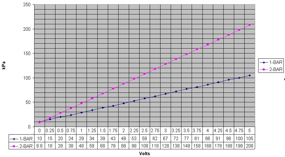
Every table that references MAP or kPa will have to be changed. You can't just go into these tables and cut all the values in half, what effectively has to happen is that the resolution of the data gets cut in half, and then you have to fill in the upper kPa values yourself. Data has to be moved from higher kPa rows to lower kPa based on the voltage of the MAP sensor for that kPa value.
For example,
The voltage for 10kPA on the 1-BAR sensor is 0 volts. 0 volts on a 2-BAR sensor is 8.8kPa. Close enough, the 10kPa row will stay the same.
Next row, 15kPa. The 1-BAR voltage for 15kPa is 0.25 volts. The same voltage on the 2-BAR sensor is 18kPa. That's closer to 20, so what you need to do here is copy the data from the 20kPa row into 15kPa. It can be fine-tuned (normalized) later.
Next row, 20kPa. The 1-BAR voltage is 0.5 volts. The same voltage on the 2-BAR sensor is 28kPa. Into row 20 copy 30's data.
Repeat this process until you reach 60kPa (2.25 volts) into which you'll be copying the data from the 105kPa row. From 65kPa and on you have to come up with your own values because the entire top half of every table (boost) will now be filled in. The easiest way to do this is to plot the values from the table out to make a curve. Usually extending the curve and plotting the numbers will be a good place to start. By plotting a curve you can see where there are spikes from the data values rounding to the nearest kPa value. These can be adjusted to smooth them out. It can also be done mathematically if you calculate a delta factor for each kPa vale between the two MAP sensors.
Do not forget to do the timing tables! These are all based on MAP. Transmission too...
One of the things you have to take into consideration is that the 1-bar and 2-bar MAP sensors have voltage scales that do not line up 2:1. I graphed my spreadsheet for you:
Every table that references MAP or kPa will have to be changed. You can't just go into these tables and cut all the values in half, what effectively has to happen is that the resolution of the data gets cut in half, and then you have to fill in the upper kPa values yourself. Data has to be moved from higher kPa rows to lower kPa based on the voltage of the MAP sensor for that kPa value.
For example,
The voltage for 10kPA on the 1-BAR sensor is 0 volts. 0 volts on a 2-BAR sensor is 8.8kPa. Close enough, the 10kPa row will stay the same.
Next row, 15kPa. The 1-BAR voltage for 15kPa is 0.25 volts. The same voltage on the 2-BAR sensor is 18kPa. That's closer to 20, so what you need to do here is copy the data from the 20kPa row into 15kPa. It can be fine-tuned (normalized) later.
Next row, 20kPa. The 1-BAR voltage is 0.5 volts. The same voltage on the 2-BAR sensor is 28kPa. Into row 20 copy 30's data.
Repeat this process until you reach 60kPa (2.25 volts) into which you'll be copying the data from the 105kPa row. From 65kPa and on you have to come up with your own values because the entire top half of every table (boost) will now be filled in. The easiest way to do this is to plot the values from the table out to make a curve. Usually extending the curve and plotting the numbers will be a good place to start. By plotting a curve you can see where there are spikes from the data values rounding to the nearest kPa value. These can be adjusted to smooth them out. It can also be done mathematically if you calculate a delta factor for each kPa vale between the two MAP sensors.
Do not forget to do the timing tables! These are all based on MAP. Transmission too...
Thread Starter
Joined: Oct 2005
Posts: 2,336
Likes: 67
From: wyoming @ 12000 DA...
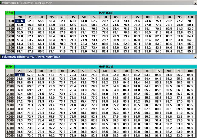
Alright. This is what i have come up with after scaling the tables how you explained they needed to be.
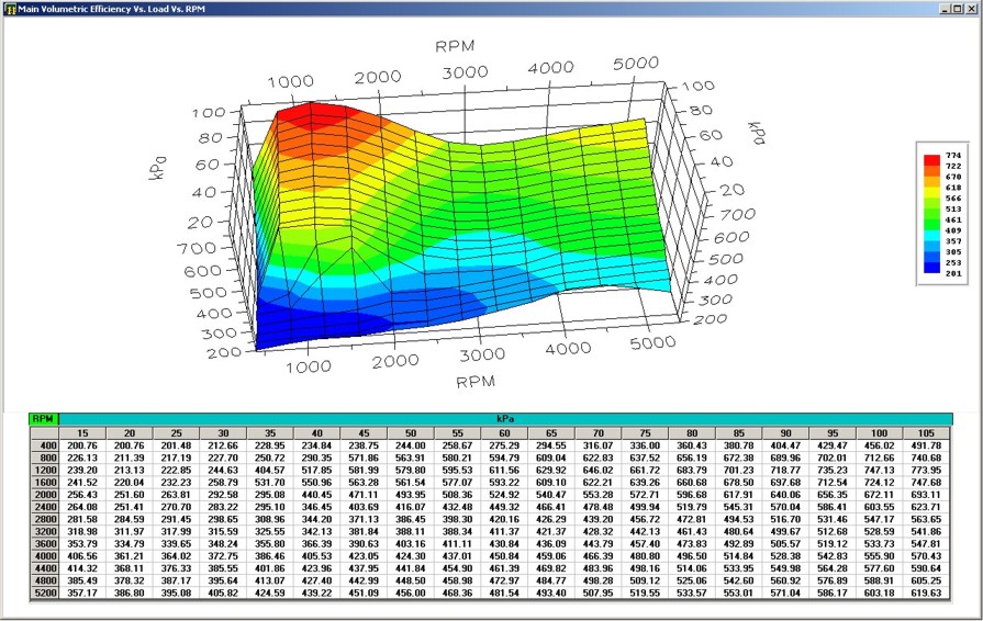
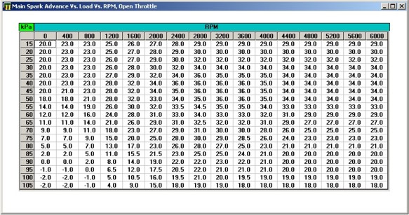
Now remember, all the values entered into the VE table have been multiplied by 0.9. I also multiplied the injector constant by the same. This basicly made me able to trick the computer in letting me enter in values over 100 in the ve table. To get the actual value of the number, reverse the scale of course (number*1.1).
Now from the numbers entered into this here alone (not looking at pe), Im betting i'd be rich coming into boost and lean out as more comes in. Would you mind posting your tables??
Here is VE
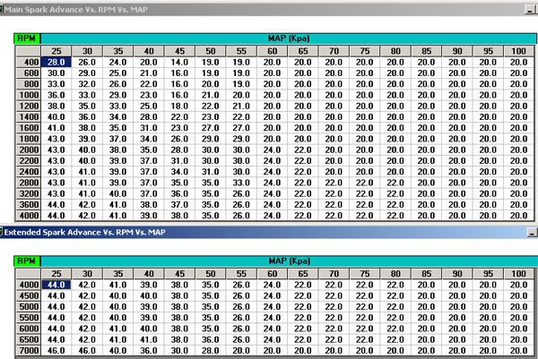
And timing
Now remember, all the values entered into the VE table have been multiplied by 0.9. I also multiplied the injector constant by the same. This basicly made me able to trick the computer in letting me enter in values over 100 in the ve table. To get the actual value of the number, reverse the scale of course (number*1.1).
Now from the numbers entered into this here alone (not looking at pe), Im betting i'd be rich coming into boost and lean out as more comes in. Would you mind posting your tables??
Here is VE
And timing
Trending Topics
Thread Starter
Joined: Oct 2005
Posts: 2,336
Likes: 67
From: wyoming @ 12000 DA...
And my other question is, since your pcm reads to 105, and mine does not. Will my scaling on the tables be done as you described?
Still seems my computer would react to a 2bar by exactly twice.
It just depends on how my pcm interprets the map voltage compared to yours. . .
Still seems my computer would react to a 2bar by exactly twice.
It just depends on how my pcm interprets the map voltage compared to yours. . .
LS1 Tech Stories
The Best V8 Stories One Small Block at Time

Gas Monkey Built a 6-Wheel Ferrari Testarossa With a Corvette LT4 Engine
Verdad Gallardo
7 Most Reliable High-Performance Engines GM Has Ever Built
Verdad Gallardo
Amazing '71 Camaro Restomod Is Modern Muscle Car Under the Skin
Verdad Gallardo
6 Common C5 Corvette Failures and What's Involved In Repairing Them
Pouria Savadkouei
Retro Modern Bandit Pontiac Trans AM Comes With Burt Reynolds' Autograph
Verdad Gallardo
Top 10 Greatest Cadillac V Series Performance Models Ever, Ranked
Pouria Savadkouei
Top 10 Most Powerful Chevy Trucks Ever Made!

Hennessey's New Supercharged Silverado ZR2 Has 700 HP
Verdad Gallardo
Coachbuilt N2A Anteros Is an LS2-Powered C6 Corvette In Italian Clothes
Verdad Gallardo The tables look good. For timing you're probably going to want to taper off as boost builds to prevent detonation. It will take some logging to find out where those should be.
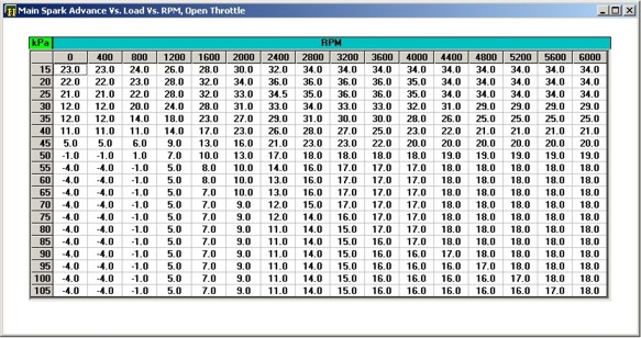
Vortec PCMs use a different formula for "VE" than the OBD-I PCM does, so even in the stock tune there are many cells over 100. This will look strange to you. For reference, this was a GM HT383 with Edelbrock E-Tec 200 heads and a 214/220 @ 0.050" and 114LSA cam with 1.6:1 rockers, 62# injectors, and long tube headers. Boost was 9-10psi intercooled, 160 T-stat, 91 octane.
Stock VE:
2-Bar VE: (the inflated low-RPM VE is compensation for lack of "pump-shot" tables in this PCM calibration)
Stock Timing:
2-Bar Timing:
The tables look good. For timing you're probably going to want to taper off as boost builds to prevent detonation. It will take some logging to find out where those should be.
Vortec PCMs use a different formula for "VE" than the OBD-I PCM does, so even in the stock tune there are many cells over 100. This will look strange to you. For reference, this was a GM HT383 with Edelbrock E-Tec 200 heads and a 214/220 @ 0.050" and 114LSA cam with 1.6:1 rockers, 62# injectors, and long tube headers. Boost was 9-10psi intercooled, 160 T-stat, 91 octane.
Stock VE:
2-Bar VE:
Stock Timing:
2-Bar Timing:
I don't think there are very many people doing this. Back when I originally wanted to eliminate the Supercharger's auxiliary injectors and run 8 larger real injectors with the stock PCM, there was nobody doing this on the older "black-box" PCM. Everyone I could find that what doing it on a stock OS and not a custom EFI Live 2-Bar OS had been tuned by one of the mail-order guys who basically just adjusts the injector constant for larger injectors and lets the PCM compensate with MAF data only. This is dangerous since the MAP tops out of 105kPa and MAF becomes the only thing telling the PCM there's more air flowing. In other words PCM is not boost-aware, so for timing it will just use whatever the highest kPa value is (105 for newer PCMs, 100 for yours) and apply that to the greater airflow. MAP will be pegged at max kPa as airflow increases. PCM also uses the same VE value for all bost since not boost-aware. Supposedly this actually works okay for mild boost they all say. My probaly with the 1-BAR Mass-Air approach is having no control over timing or AFR as boost increases. Also, MAF sensors don't work well at velocities so much higer than their native range. The other way of feeding boost with a stock PCM is to install a 2-Bar capable Custom Operating System ("COS") that is calibrated for the correct MAP sensor and all VE and injector values can be the real deal with no deception going on. Of course, custom operating systems are only available for the Newer Gen-III motor PCM's known as "411" and higher. What you're doing is totally different from either OBd-II solution since your setup cannot meter air flow and you cannot install a COS. Speed-density needs a MAP that can cover the entire range of pressures the manifold will ever see.
Thread Starter
Joined: Oct 2005
Posts: 2,336
Likes: 67
From: wyoming @ 12000 DA...
it looks like here Brian at PCM for less dissabled the burst knock. Now im not sure what this will "all" disable (obviously at least burst knock) and if I should use it or not. Also... what is the exact definition to burst knock?
anyways.. here is the pic
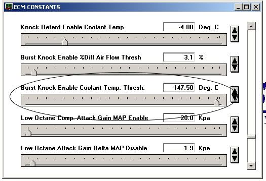
anyways.. here is the pic
Thread Starter
Joined: Oct 2005
Posts: 2,336
Likes: 67
From: wyoming @ 12000 DA...
I don't think there are very many people doing this. Back when I originally wanted to eliminate the Supercharger's auxiliary injectors and run 8 larger real injectors with the stock PCM, there was nobody doing this on the older "black-box" PCM. Everyone I could find that what doing it on a stock OS and not a custom EFI Live 2-Bar OS had been tuned by one of the mail-order guys who basically just adjusts the injector constant for larger injectors and lets the PCM compensate with MAF data only. This is dangerous since the MAP tops out of 105kPa and MAF becomes the only thing telling the PCM there's more air flowing. In other words PCM is not boost-aware, so for timing it will just use whatever the highest kPa value is (105 for newer PCMs, 100 for yours) and apply that to the greater airflow. MAP will be pegged at max kPa as airflow increases. PCM also uses the same VE value for all bost since not boost-aware. Supposedly this actually works okay for mild boost they all say. My probaly with the 1-BAR Mass-Air approach is having no control over timing or AFR as boost increases. Also, MAF sensors don't work well at velocities so much higer than their native range. The other way of feeding boost with a stock PCM is to install a 2-Bar capable Custom Operating System ("COS") that is calibrated for the correct MAP sensor and all VE and injector values can be the real deal with no deception going on. Of course, custom operating systems are only available for the Newer Gen-III motor PCM's known as "411" and higher. What you're doing is totally different from either OBd-II solution since your setup cannot meter air flow and you cannot install a COS. Speed-density needs a MAP that can cover the entire range of pressures the manifold will ever see.
I will have my map sensor soon and will give what i have going a try.
THANKS A TON FOR THE HELP!!! Can't say it enough
Last edited by Dragframe; Feb 19, 2008 at 07:26 PM.

Teching In
Joined: Oct 2007
Posts: 1
Likes: 0
any updates?????? how close to being finished? already running?
I am going to do basically the same thing. 74 mm garrett lt1 in a caprice wagon.
I made a test tool. it was a mini regulator with a 6" 30 psi gauge attached that to an air compressor. I plugged my 2 bar map into my harness and connected the port to the test tool. turned the key on engine not running i datalogged with datamaster and let datamaster think i had a 1bar map. I started at one psi. blipped throttle to wide open ( so i would have a reference point later) then moved on to 2 psi etc. until i reached 18 psi which is past what the 2 bar map will read ( i wanted to make sure i got it all). i took this data and have started a excel file i can use to copy and paste my tunercat files that are relevant to the map sensor operation. I have yet to pull a vacuum on the 2 bar sensor but have plans to do that this week if i get time.
I don't think he ever got around to implementing this. Right now, he has the LT1 out of the car and is putting in a 5.3 and gona turbo it, and run it off the LS1 type PCM so he can 2 bar tune it with EFIlive.