When you click on links to various merchants on this site and make a purchase, this can result in this site earning a commission. Affiliate programs and affiliations include, but are not limited to, the eBay Partner Network.
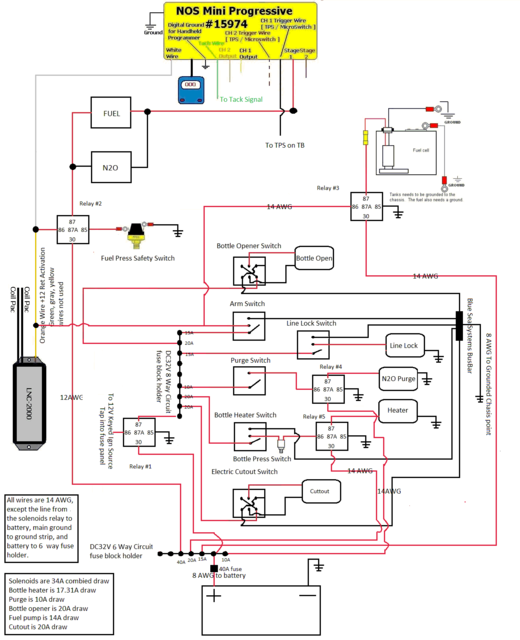
Attached is the wiring diagram that we use. If you have any questions feel free to contact me at 254-848-4300 ext 111 or email me at Matt@NitrousOutlet.com and ill be happy to answer them! -Matt
I would make sure users are careful about the source of the 12 volt switched power - the purge solenoid and the bottle opener are drawing current from that 12 volt switched power source in that diagram. Many vehicle interior switched source power locations likely shouldn't be used to draw that much current. Using relays to enable the purge solenoid and the remote bottle opener would allow them to get current from another source and you wouldn't have to have high current going all the way to the switch panel.
Also it looks like the way this is wired the LNC-2000 timing retard will be active (ie taking out timing) when ever the arming switch to the nitrous controller is active, regardless of if have nitrous actually spraying.
Since that controller has programmable outputs why not use one of the programmable outputs to activate the LNC-2000 timing retard only when the nitrous is actually spraying? I believe the outputs are ground type so you would have to use a relay to convert the output to a +12 volt output to enable the LNC-2000 timing retard.
Originally Posted by Nitro Dave's Nitrous Outlet
Attached is the wiring diagram that we use. If you have any questions feel free to contact me at 254-848-4300 ext 111 or email me at Matt@NitrousOutlet.com and ill be happy to answer them! -Matt
Hey Jason,
We recommend this wiring because the only way to ensure that the lnc-2000 is working is to feel the timing and power come out of the car. If for some reason the box doesn't work, there's a wiring issue, faulty relay etc., I'd rather find out by the car feeling sluggish rather than blow my intake off. It's just a precautionary measure. While these boxes have an excellent track record for reliability, we typically err on the side of caution. However, this doesn't work well for race car applications because it can be hard to get up on the 2-step with a bunch of timing yanked out. If our customer needs instruction on wiring the mini to the LNC, we can provide that as well.
Wiring diagram modified to include relay between purge and switch.
Can I use a 6 way fused distribution block with 6 wires leading to each of the 6 switches, and just wire the keyed 12V wire coming from the factory fuse box to the main terminal on the fused distribution block or will that over load it?
Last edited by 5.7stroker; May 6, 2016 at 04:39 PM.
I agree with using the output to trigger pulling timing. There is et to be had by delaying the timing being pulled even .02 or so. This lets the motor rev easier until the nitrous actually reaches the motor. It's also helpful if your delaying the nitrous for some reason you can delay the timing being pulled.
As far as testing the box that's easy. The outputs are ground triggers. Tap another wire on the circuit. I have a covered female spade that tuck under the edge of the console. When I get to the track I arm the nitrous and touch the spade on a bolt that grounds, if the motor stumbles I know it's pulling timing. Now, I have an iat tricker box ,but it's the same idea.
Even if launching off the nitrous, use the programmable trigger?
Gas Monkey Built a 6-Wheel Ferrari Testarossa With a Corvette LT4 Engine
Slideshow: The controversial Ferrari F6 swaps its original flat-12 for a Corvette Z06-derived LT4 V8 and sends power to four rear wheels through a custom-built drivetrain.
7 Most Reliable High-Performance Engines GM Has Ever Built
Slideshow:These GM engines didn't just make huge power, they survived abuse, boost, track days, and six-digit mileage with a reputation for refusing to quit.
6 Common C5 Corvette Failures and What's Involved In Repairing Them
Slideshow: From wobbling harmonic balancers to failed EBCMs, these are the issues that define long-term C5 ownership and what repairs typically involve.
Retro Modern Bandit Pontiac Trans AM Comes With Burt Reynolds' Autograph
Slideshow: A modern Camaro transformed into a retro icon, this limited-run "Bandit" build blends nostalgia with brute force in a way few revivals manage.
Top 10 Greatest Cadillac V Series Performance Models Ever, Ranked
Slideshow: Cadillac didn't just crash the high-performance luxury vehicle party, it showed up loud, supercharged, and occasionally a little unhinged...