When you click on links to various merchants on this site and make a purchase, this can result in this site earning a commission. Affiliate programs and affiliations include, but are not limited to, the eBay Partner Network.
Water air intercooler air bleeding/expansion tank routing help
Ripped off my A2A due to my 87 firebird being a bottom feeder the A2A really limited airflow to the engine and tranny cooler. Motor is a 5.3 with ported stock heads, custom cam motion 214/228 cam, stock truck intake and a torqstorm supercharger running 12psi before cam and head swap. For some reason I'm only seeing 8psi at 5100 Rpms but I think it was a restriction on the supercharger filter or the A2A intercooler. I'm also spraying a small 400-500ml of 50/50 meth water injection to be safe on 93 pump gas. Car is only
street driven but driven hard
Anways i I pulled the setup off and starting from scratch on A2W. Just got my cxracing A2W 12x11x4.5 IC and running 3" tubing. And got it situated where I want it. The issue is the IC is the highest point in the system. I'm waiting on a 1 gallon tank that will go in my driver battery tray area, I'm running a Prius inverter pump below that that goes into a Prius inverter radiator. Before u talk **** about the Prius stuff lol the pump is a brushless 90k mile or 3000 hr pump, very quiet and I've flowed it at 5GPM with 1/2" ID line so it will do fine. That inverter radiator is 4"x23"x3/4" and it might be a tad small but I have a much larger heat exchanger I can use but am holding off as I want to keep as little in front of the tranny cooler and radiator. all lines will be 3/4" ID.
The way I have it planned is... water reservoir feeds into pump inlet, pump outlet pushes water through heat exchanger, water exits heat exchanger and goes to IC inlet, water exits IC back to reservoir. Now since the IC is the highest point I'm thinking of adding a small 1 quart expansion tank with a 6lb pressure cap. But how do I connect that into the setup? Do I just tap into the IC exit line and plumb that to the expansion tank and connect the expansion tank to the top of the reservoir? Do I need to drill a hole and tap into the IC's actual highest point where air can be trapped and run that to the expansion tank?
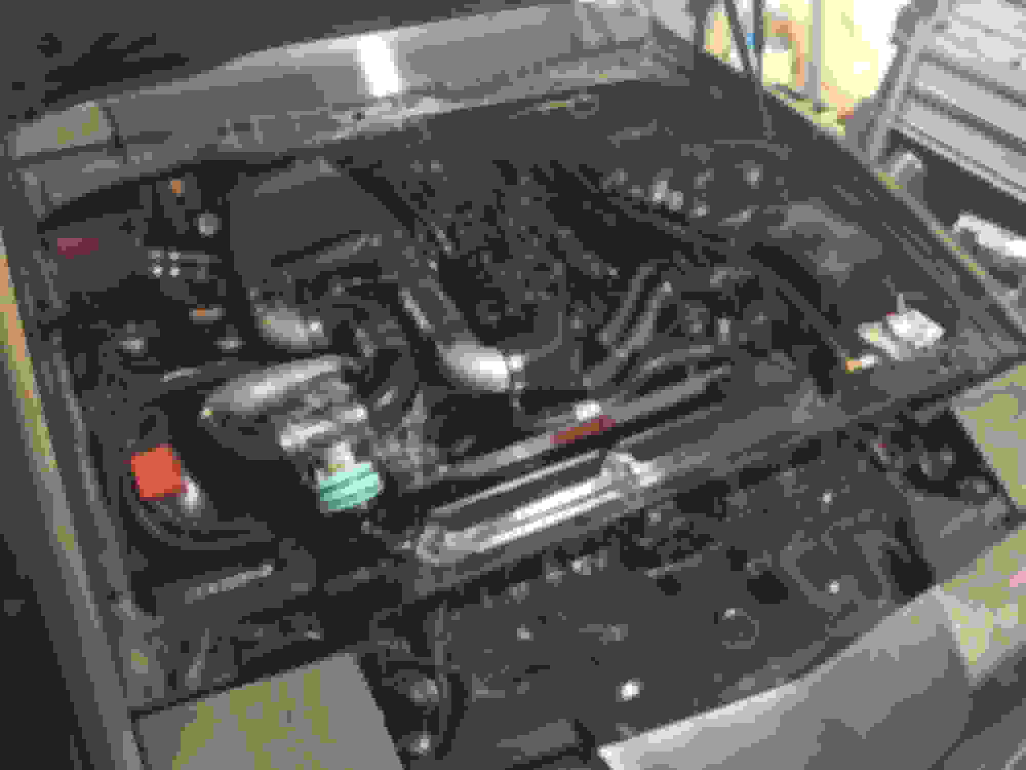
heres a pic to show where I'm at with IC location.
remote headers always install on the pump inlet side of the system and naturally would need to be the highest point in the system.
remote headers?
The inlet side of the pump is below the 1 gallon reservoir. The intercooler is he highest point and it's like 6" higher than the top of the reservoir tank. Can u just add a port to the top of the IC highest point and run that to a expansion tank? Does the expansion tank need to recirculate back to the reservoir? Or can I just hook it up and use the expansion tank like an overflow that can hold pressure if need be.
I just finished mounting the IC last night. I have the expansion tank mounted just not sure how I want to tap the IC or if I can just tap into the return from the IC to the reservoir.
Expansion tank is aluminum cylinder at the top of the firewall Tank reservoir is bottom right of the pic with the 2 bungs out the top Bottom fitting feeds the pump below. Top will be return from the IC. I was going to run a line from the top to the expansion tank and a line from the expansion tank to the IC for air bleeding/filling. And plug the other 2.
If this is not the highest point, filling the system properly is going to get rather difficult ?
If you want the IC core to self bleed as a higher point, then yes a small line going back to your "expansion tank" as you call it would do this. The pump will circulate a small amount of water via this at all times to ensure the main core is always full of water.
But how will you fill a system effectively where water will always want to escape via your low mounted expansion tank ? The core is always going to be trying to empty itself.
your correct. But my expansion tank should be equal to the height of the IC core so it should be the highest point in the system. But I still need to tap the highest point of the IC to allow the trapped air to escape to the expansion tank. But my
concern with this is if I plumb the expansion tank like in a radiator setup then I need one line going to the top of the expansion tank and another larger line coming out of the bottom which allows the fluid to recirculate to the return hose. If that's the case then the expansion tank would have to be constantly circulating water which is how it should work but I'm unsure if I will get the flow being that it's really just excess through a small line to the expansion tank. I was thinking of using 1/8" silicone hose from the IC to the expansion tank and then 3/8" from the expansion tank to the reservoir. That would give me a high point to fill from and bleed air out of the system.
I don't have anything useful to add that other people haven't already said, but I would like to add: Very nice layout you have there. You made great use of the space you were given. I always wanted to do a FI LS 3rd gen. Kudos to you
Looks great. I am working on a super budget silverado work truck with an air water over the driver side valve cover. Didn't give much thought about header tanks....
Anyways, google cpc quick disconnects. Push the button on the disconnect and its spill free if you need to remove the cooler. I would imagine they have a 1/2 npt 90 side, and then the other side could be 3/4 hose barb.
I ended up changing the layout of the cold side piping completely lol. Didn't like the tube running over the supercharger and took me a while to figure out what fit where like a puzzle. But it's finally done I think! Gives me more clearance everywhere honestly. I can delete the meth injection bungs (and an extra coupler) and just use 1 full aluminum tube and just drill and tap it for a meth nozzle but for now I'm going to just leave it and see if I like it. The issue with this is oil filling and checking the oil dipstick is going to be a PITA! Lol.
So now onto the bleeding. I drilled and tapped the rear of the IC, the return side. I put a 5/16" barb on a 90 to clear the firewall. So I have 2 ways to plumb this air bleed. I have a 3/4" tee fitting that has a 3/8" barb as the T and the other 2 are 3/4" OD nipples. Can I just run a hose from the bleed port on the back of the IC to the Tee fitting in the return line and be done with this? Seems like the air would push out and push it through the return hose back to the reservoir. But it also seems like air could get trapped in the bleed hose as it will be the highest point. Option 2 is to mount the expansion tank off the intake in the cowl area... will let me push it up about 1" higher than the IC and should work perfect. Then run a line from the bottom to the reservoir and this will act as my highest fill point. The only negative is I have this ugly expansion tank hanging off the intake like a tumor lol.
Thoughts about everything? Lol
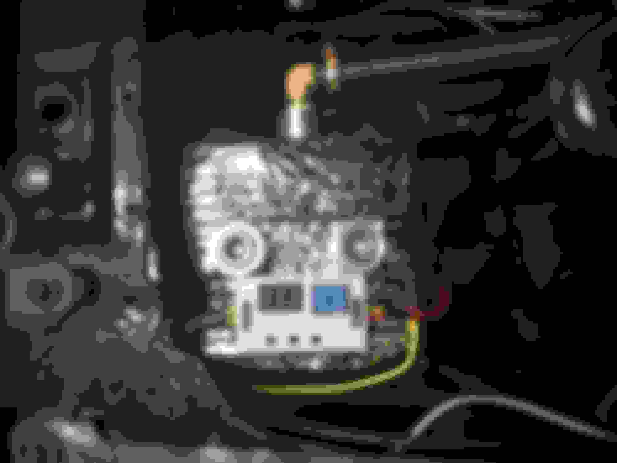
Bleed fitting and rear IC return fitting. The plastic Tee is right to the bleed fitting. this is probably where I would tap for my one option with a shorter bit of hose of course. Bleed fitting line to top of expansion tank. Will run a line from the bottom to the reservoir but this would be its location.
I wouldn't think air stuck in the hose would affect anything. Put a T in your 5/16 bleed line with a petcock so you can check and see if air comes out with the pump running.
I have a similar problem with mine and I just put a 1/8 pipe plug in the highest point to bleed air, I think I'm going to go back and put a line back to the return like you did.
I agree. But I dont like the fact that its not self bleeding if air stays in that line. It also doesn't really give me a great point to fill from. As I would have to disconnect the line or use A Tee with a hose attached to a small funnel lol. Ive seen people just use a $15 manual bleed valve and just hold it open till water comes out with the pump on. But they have to manually check it and do it if needed. I'd rather something just do it automatically.
Took some time to figure out plumbing and the expansion tank didn't work out. No matter where I placed it to be higher than the IC it always stuck out and looked like ***.
So I decided to go simple. At the moment I'm not going to run a bleed valve in the bleed port. I tee'd into the 3/4" rerun line and ran a 3/8" hose to the bleed port in the IC. I then Tee'd into that with a 3/8" barb tee. I put a cap on the exposed port to close it off. To bleed the air I just pull the cap off, to fill the system I just run a 3/8" hose off the tee to fill from a funnel or whatever. Keeps everything short and sweet by the IC.
Ive finished up all hose runs except from the heat exchanger outlet to the IC inlet. It should be challenging due to haveibg to snake it through the IC piping and supercharger but hopefully it's not that bad.
Ive also finished wiring up the pump and the programmable delay relay. I bench tested it and programmed it for 60s run time after boost is completed. This means once it gets triggered by the pump 12v via the progressive controller it will wait till it stops seeing 12v and then start a 60s countdown and keep the pump on, it's an infinite loop so it can be activated as many times as I want. The way I see it if the pump flows 3.5 GPM or 1 gallon every 17s through the heat exchanger as a restriction(wasn't able to test through the IC as well) that a 60sec run time should give me 3.5 gallons of circulated flow during and after boost (pump also runs during boost so that flow is additional). I hope that's enough. If not it takes like 5s to reprogram while in the car.
Going to look over the wires next. That Tee is the highest point. Plus bc it's a hose I can just pull it up for easy filling and bleeding.
It's all done guys. Finished her up today and ran her for the first time since swapping intercoolers and cold sides.
First startup she was running super lean! 19.5:1 and fluctuating but it was idling at 14-15:1 before with the FMIC and crap. So there was a ton more air with the new system for It to lean out 4-5 full points. So I added a bunch of fuel
back in and ran her till she got up to operating temp 180*F. I noticed the IC pipes where I have my pre and post IC IAT sensors located were getting alittle heat soaked being that they are over the warm supercharger and motor. Close to 70 ambient today and IATs steadily rose to 90 ish degrees. Pre and post IC were reading in the 100-115*F range. I was still seeing a temp drop before and after the IF but was like 15*F. Car sat in a tent with no air movement besides the cooling fans.
Sure enough my HVAC tape and insulation showed up and I got to work on wrapping the IC, pipes with IAT sensors and my reservoir tank to help with heat soak. I then pastidipped the top half of the IC to help tone down the shiny... I hate shiny! I haven't started it since but I'm going to take it to work tmrw and see what alittle street driving feels like and temp wise.
It's all mounted in a hot environment, battling heat soak will be near impossible really, especially when slow moving or stationary and worse when the cooling fan is running blowing even more hot air around it all.
Some vents mid/front bonnet would help expel some of that hot air, but not too far forward as they need to be far enough back that they would be in a low pressure area to try and encourage air out
yea. I knew this was going to be an issue. Going to see if I can open the hood scoop vent to help.
Drove it to work today and besides needing to adjust my TV cable (late shifts) running pretty good. Saw 120-130 on the SC oulet and about 90 on the IAT sensor in the intake, but going to have to go over my log. 67*F ambient and only 45% humidity.
But I think I'm going to need more pump at this point. I don't see the Bosch as an upgrade at this point so I might have to go bigger.
Gas Monkey Built a 6-Wheel Ferrari Testarossa With a Corvette LT4 Engine
Slideshow: The controversial Ferrari F6 swaps its original flat-12 for a Corvette Z06-derived LT4 V8 and sends power to four rear wheels through a custom-built drivetrain.
7 Most Reliable High-Performance Engines GM Has Ever Built
Slideshow:These GM engines didn't just make huge power, they survived abuse, boost, track days, and six-digit mileage with a reputation for refusing to quit.
6 Common C5 Corvette Failures and What's Involved In Repairing Them
Slideshow: From wobbling harmonic balancers to failed EBCMs, these are the issues that define long-term C5 ownership and what repairs typically involve.
Retro Modern Bandit Pontiac Trans AM Comes With Burt Reynolds' Autograph
Slideshow: A modern Camaro transformed into a retro icon, this limited-run "Bandit" build blends nostalgia with brute force in a way few revivals manage.
Top 10 Greatest Cadillac V Series Performance Models Ever, Ranked
Slideshow: Cadillac didn't just crash the high-performance luxury vehicle party, it showed up loud, supercharged, and occasionally a little unhinged...