When you click on links to various merchants on this site and make a purchase, this can result in this site earning a commission. Affiliate programs and affiliations include, but are not limited to, the eBay Partner Network.
Here's how it progressed over time..........:
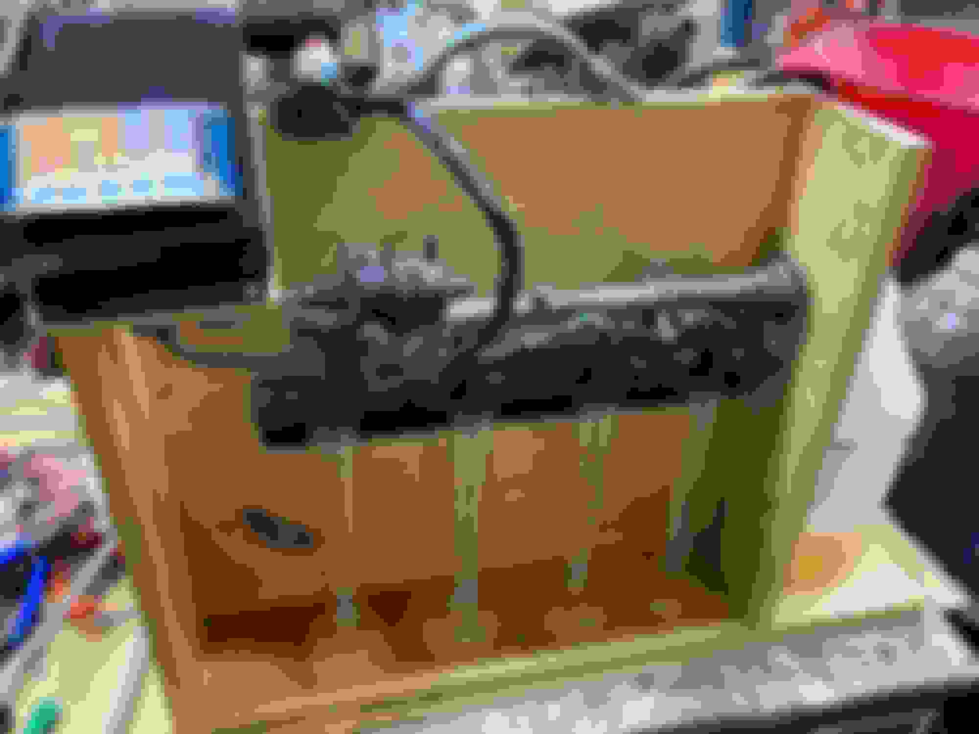
I know there are some cheap fuel injector testers out there. I like DIY, so as usual, I built my own.
I'm willing to share info about my design, and open to listen about improvements, safety etc. As usual, I do an initial design and make changes along the way.
Touchscreen controlled by Arduino. Has a 30 amp supply. Fuel pump is a wallbro 255. Fuel pressure is adjustable.
Can store 6 different tests that can be saved via the touchscreen. Probably going to add more saved tests. Remembers tests after power is shut off.
Can run any injector or all 4 one after the other for any test.
Can run just the fuel pump to test for leaking injectors.
Once a test starts, touching any button on the screen stops it.
Adruino mega (yes could use a nano, but debugging is easier with extra serial ports).
Screen can display voltage and fuel pressure.
Screen has progress bar to help judge if test will overflow beaker and needs to be stopped.
Might add peak and hold.
Might consider bluetoooth to laptop instead of touchscreen. Don't feel like writing the laptop code though.
Might add current sensing and injector response graph to touchscreen.
Thinking about adding capacitors to output of power supply to help regulate the voltage.
Currently testing with mineral spirits. Results have been very repeatable.
Each saved test has pulsewidth, period (expressed in microseconds) and number of pulses.
OK, when the pressure changes in a "sealed" flask, the precise measurement WILL STATE that volume of material.
Thus VERY simple for data recording.
Wow. You DO sound like Lance.... But since the VOLUME is the target of your pressure findings.... the VOLUME can also be measured by far simpler methods....
OK, when the pressure changes in a "sealed" flask, the precise measurement WILL STATE that volume of material.
Thus VERY simple for data recording.
Yeah, Not happening. in addition to overly complicated and the safety issues already stated, increasing pressure would constantly change the flow rate.
Was testing a couple sets of injectors today and realized I need to relieve the pressure before I remove a set of injectors. I didn't think my walbro 255 had a one way valve, but apparently something is maintaining fuel pressure after everything is turned off. Not sure how I'll do it. Easiest would be to check if there is some valving on the pump. If not, then maybe run the pump backwards?? Worst case, install some additional valve and hose.
just a valve on the rail back to the source.. I'd use a solvent specific valve for this or if you wanna get fancy use a fuel tank switch valve off a pickup.. Can get those in a wrecking yard..
Or turn the pump off and fire the injectors..
I'm re-thinking the graduated cylinder approach. It's a pain in the *** to read the cylinders after each test, record the volume and empty them each time. For each injector, I could see doing this 3 times (or more), an idle test, a 90% test and a full blast test.
I'm thinking about installing four 1 Kilo load cells. They are about $9 each with the amplifiers, shipped from US. Instead of graduated cylinders I could use 1/2 liter or 1 liter plastic bottles instead of graduated cylinders. For each injector, the arduino could read a starting weight, run the idle tests, record the weight, run a 90% test, record the weight and then run a full blast test...... After all 4 injectors, it could print out the results to the display or serial port, I can take a screenshot and or export to excel.
Just pulled the trigger on a couple of these load cells.
This is where I always get into trouble. The tester works fine as is and I should just leave it alone once I install the pressure relief.
But I just can't leave it alone. Now that I'm planning on automating the readings with the load cells, which means I can run any number of tests without any human interaction, I'm rethinking the need for the entire touch screen.
Instead of the touch screen, there are at least two ways I can think of to run the tests and get results, both require a laptop instead of the touchscreen.
1) I can just use the arduino serial monitor to set up and control the test and get the results. I could just type in simple commands to set up and start the runs instead of buttons. The Arduino can interpret the results and spit out all the info about the injectors in terms of flow rates for each injector back to the serial monitor. This is probably the easier of the two.
2) I think I can stream data directly from the arduino into Excel and back. Excel can replace the touchscreen and become the control for the tester. There can be buttons on the Excel screen that run the tests and the results get sent back to Excel automatically. Excel can interpret the results and spit out all the info about the injectors in terms of flow rates for each injector. Excel could even create charts and graphs. If I add the current sensing capability, it could even draw a graph that shows the injectors opening response curve.
just a valve on the rail back to the source.. I'd use a solvent specific valve for this or if you wanna get fancy use a fuel tank switch valve off a pickup.. Can get those in a wrecking yard..
Or turn the pump off and fire the injectors..
Sorry I didn't notice this before. It's brilliantly simple. Especially the part about firing the injectors with no pump on.
I still want a valve to let the fuel drain back so the fuel rail is empty when I swap out the injectors.
I added a touch screen routine that runs the injectors without having the pump on. That drops the pressure in the fuel rail for when I change out injectors. Works great. thanks pdxmotorhead.
Added a valve to let the fuel rail drain back to the return line. I have long hoses to the fuel rail, can lift it high and let gravity empty it. Marginal results, but worth it.
Added a .1 ohm resistor in series with the mosfets that run the injectors. Changed the voltage reference to internal 1.1 volts so I can read the current running through the resistor. The Arduino can read the current once roughly every 20 microseconds.
Now you can observe the armature position AND travel speed.
The MOST important item is to observe the lowest turn on time, in PW, that the tested injector can flow fuel.
Here is a chart of the current in one of the 1000cc Injectors I tested. sent it to a pivot chart on Excel and learned some interesting things.
Left side is the current through the injector.
Bottom is the time since the injector was fired on microseconds.
These injectors would barely fire at 1.5 millisecond pulse-width. They appeared to flow ok at 1.7ms. The chart explains alot.
One would think that the split second that the injector is turned on, current would be on. But in the real world, the injector is an inductor. So current doesn't flow right away.
There is an interesting dip in the current around 1.45 milliseconds. I believe the ball hasn't moved off the seat until around 1.27 ms. Once the ball began to move, the current dropped to a low around 1.45ms. I think the ball was rising until around 2.356ms when it reached maximum throw. There may have been a bounce around 2.892 and another one around 3.24ms.
I also ran low impedance one and it's around 4A. I'll post that one up later.
 08-13-2021, 08:46 AM