
Tach signal specifics


Thread Starter
TECH Addict
Joined: Feb 2012
Posts: 2,103
Likes: 21
I had a nifty idea that will be a ways off from actually making this, but I was looking for some info on tach signals etc.
That being said, I've read that a tach signal from the PCM is a square wave? If so, how does our factory tach use this signal? Is the factory tach a stepper motor?
I would assume some sort of converting needs to happen turning the PCM tach signal into a simplified associated voltage/resistance for the tach to use? Or does the PCM convert the signal and the factory gauge sees a simple voltage/resistance reading?
So at idle for instance the tach (or PCM) converted th signal to .5V which it uses to turn the needle to the ~800RPM spot on the gauge.
Can anyone confirm or deny this thought process?
Thread Starter
TECH Addict
Joined: Feb 2012
Posts: 2,103
Likes: 21
According to this, there is a "simple" single wire running from the PCM Red connector pin A13 (white) that runs to the instrument cluster.
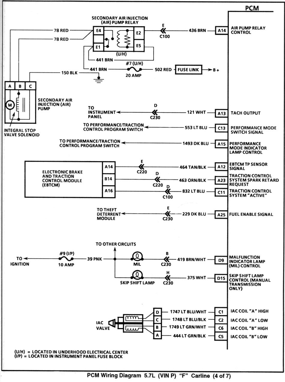
So I'm hoping this wire is carrying a simple voltage signal...
So I'm hoping this wire is carrying a simple voltage signal...


Joined: Nov 2003
Posts: 11,331
Likes: 346
From: Jacksonville, FL (originally from Toronto Canada)
Interestingly enough, the GM service manual goes into great detail on the operation of the speedometer but for the tach says only "The tachometer signal comes from the powertrain control module (PCM). The tachometer displays the engine speed in thousands of revolutions per minute (RPM)." That's it... the entire description of tach operation.
I suspect that the tach signal works much the same as the speedometer... the PCM sends DC pulses at a rate proportional to the speed. If your receiving device is slow enough to not see the individual pulses, you could probably get a pretty good approximation from the average voltage. That's how pulse width modulation works for reducing voltage for DRL headlights.
I suspect that the tach signal works much the same as the speedometer... the PCM sends DC pulses at a rate proportional to the speed. If your receiving device is slow enough to not see the individual pulses, you could probably get a pretty good approximation from the average voltage. That's how pulse width modulation works for reducing voltage for DRL headlights.
Thread Starter
TECH Addict
Joined: Feb 2012
Posts: 2,103
Likes: 21
Well on the flip side....how does an aftermarket shift light work? It splices into the tach signal then has other features to light a LED any RPM above a specific selected RPM.
The one that came with my car has little rolling dial I can select what RPM for the light to come on.
SO, depending on where/how the shift light is hooked up may give more insight into what kind of signal is coming from the PCM. My shift light is no bigger than a large permanent marker so in terms of packaging electronic components, I would think the shift light is fairly "simple".
I guess I could put a voltmeter between the battery and the Tach signal wire going to the cluster and see what I get for a readout?


