
kst8engineer - '71 Chevelle LS1/T56 build thread

 02-22-2009, 11:27 PM
#42
On The Tree
Thread Starter
iTrader: (6)

Join Date: Mar 2006
Location: Kansas
Posts: 192
Likes: 0
Received 0 Likes
on
0 Posts

The manual shows that the fuel pressure regulator and fuel pressure sensor are both located inside the fuel pump "bucket" assembly. With that in mind, I haven't figured out yet what the reason is for the external return line, unless it's just to keep the fuel circulating a little more (I'm not sure what the benefit of this would be). Does this have something to do with keeping the bucket full of fuel? I'm trying to figure out whether or not I really need to run an external return line. Maybe somebody out there has a good understanding of how the 4th-gen F-body pump/regulator/return system was intended to function.
02-23-2009, 05:45 PM
#43
On The Tree
Thread Starter
iTrader: (6)
Join Date: Mar 2006
Location: Kansas
Posts: 192
Likes: 0
Received 0 Likes
on
0 Posts
I took a look at the fuel lines from the donor car, and I see the 'T' that Old Kid mentioned above. When the fuel leaves the tank (in the stock T/A setup), it goes through the filter, then into a T-block. From the T-block, one branch goes to the fuel rail, while the other runs back to the return on the pump assembly.
Does anyone happen to know why GM ran this T-block? Does this have something to do with keeping the bucket full?
Does anyone happen to know why GM ran this T-block? Does this have something to do with keeping the bucket full?
03-10-2009, 08:51 PM
#44
On The Tree
Thread Starter
iTrader: (6)
Join Date: Mar 2006
Location: Kansas
Posts: 192
Likes: 0
Received 0 Likes
on
0 Posts
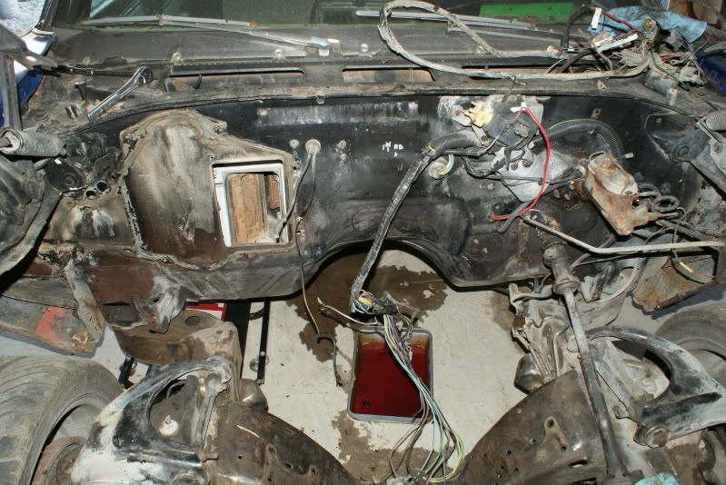
I've been working on cleaning up the frame and the underside of the body. Many cans of Gunk, a scraper, a parts brush, 2 wire-brush cup wheels on an angle grinder, and many hours later, it's not ready, but it's a lot better than it was.
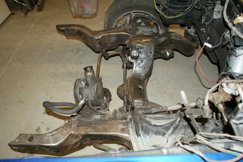
It still needs more work, but it's looking better. The old engine had been suffering from a leaking rear main seal for a few years, so the car had a healthy coating of "rust preventative" on the bottom side.
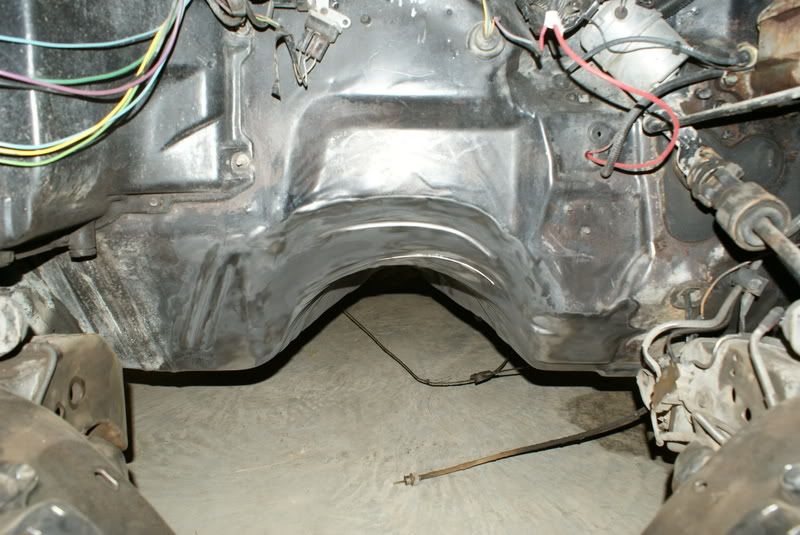
Can some of you A-body T-56 guys give me some guidance regarding the proper t-cut for the transmission tunnel? I'd like to make the tunnel cut and engine crossmember cut, then slide the engine and tranny in for a trial fit. My plan is to bend the tunnel as needed during the trial fit, then I can remove the engine and tranny and weld the tunnel back up and box the crossmember notch.
After the engine and tranny are removed and the welding is complete, I'll finish the frame and underbody cleanup. Both will be coated with Eastwood's rust converter, then the frame will be painted with Eastwood's Extreme Chassis Black, and the underside of the body will get a coat of Raptor Liner (sprayed-on bedliner).
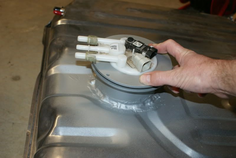
I need to pick up a few 10-24 bolts to hold the lock ring in place, but here's a pic of the SPI Chevelle tank modified to accept the '99 T/A fuel pump assembly. The trunk floor modification should be very similar to what's needed for the Impala tank, but it will look stock from the outside.
It still needs more work, but it's looking better. The old engine had been suffering from a leaking rear main seal for a few years, so the car had a healthy coating of "rust preventative" on the bottom side.
Can some of you A-body T-56 guys give me some guidance regarding the proper t-cut for the transmission tunnel? I'd like to make the tunnel cut and engine crossmember cut, then slide the engine and tranny in for a trial fit. My plan is to bend the tunnel as needed during the trial fit, then I can remove the engine and tranny and weld the tunnel back up and box the crossmember notch.
After the engine and tranny are removed and the welding is complete, I'll finish the frame and underbody cleanup. Both will be coated with Eastwood's rust converter, then the frame will be painted with Eastwood's Extreme Chassis Black, and the underside of the body will get a coat of Raptor Liner (sprayed-on bedliner).
I need to pick up a few 10-24 bolts to hold the lock ring in place, but here's a pic of the SPI Chevelle tank modified to accept the '99 T/A fuel pump assembly. The trunk floor modification should be very similar to what's needed for the Impala tank, but it will look stock from the outside.
Last edited by kst8engineer; 03-10-2009 at 09:20 PM. Reason: Added fuel tank picture
03-12-2009, 11:21 PM
#45
On The Tree
Thread Starter
iTrader: (6)
Join Date: Mar 2006
Location: Kansas
Posts: 192
Likes: 0
Received 0 Likes
on
0 Posts
I went ahead and made the T-cut tonight for the trans tunnel. I found a couple pictures from BRP and tried to follow their example for the cut.
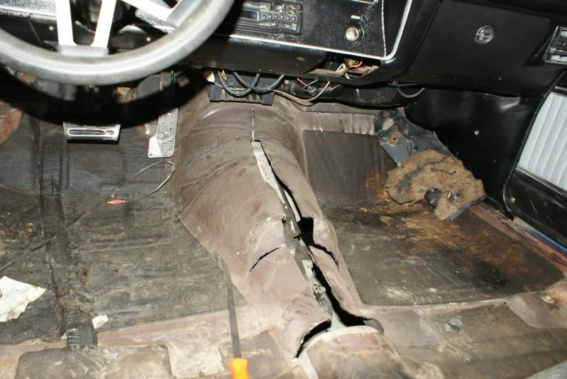
I changed my mind about the crossmember notch. Rather than notching first, I'm going to wait and see what it looks like when I do the trial fit. I'm wondering if there would be someway I could modify the A/C brackets to avoid having to notch.
I changed my mind about the crossmember notch. Rather than notching first, I'm going to wait and see what it looks like when I do the trial fit. I'm wondering if there would be someway I could modify the A/C brackets to avoid having to notch.
Last edited by kst8engineer; 03-15-2009 at 12:17 AM. Reason: Added pic
03-12-2009, 11:41 PM
#46

I know the tank is sealed up again. What about the sumping of the tank so you don't get fuel slosh. I had a stock chevelle tank modified with a rear sump and the damn thing would starve the engine of fuel. I ended up giving it away because I was so pissed. I bought the $700 tank with the pump, sump hole from the parts place.
I just hate to see you get it done and then have the same problem as me. I was running this on a FI big block.
I just hate to see you get it done and then have the same problem as me. I was running this on a FI big block.
03-13-2009, 08:25 AM
#47
On The Tree
Thread Starter
iTrader: (6)
Join Date: Mar 2006
Location: Kansas
Posts: 192
Likes: 0
Received 0 Likes
on
0 Posts
I'm hoping that the use of the F-body's factory fuel bucket system will prevent the fuel sloshing / starvation issues. I'm not positive, but I believe the return system keeps the bucket full of fuel, so basically the bucket acts as a sump within the tank.
I know the tank is sealed up again. What about the sumping of the tank so you don't get fuel slosh. I had a stock chevelle tank modified with a rear sump and the damn thing would starve the engine of fuel. I ended up giving it away because I was so pissed. I bought the $700 tank with the pump, sump hole from the parts place.
I just hate to see you get it done and then have the same problem as me. I was running this on a FI big block.
I just hate to see you get it done and then have the same problem as me. I was running this on a FI big block.
 03-13-2009, 06:26 PM
#49
On The Tree
Thread Starter
iTrader: (6)
Join Date: Mar 2006
Location: Kansas
Posts: 192
Likes: 0
Received 0 Likes
on
0 Posts
Basically it's just like the stock F-body setup. I've got a mounting flange on top of the tank, then the rubber ring from the F-body tank, then the fuel pump assembly, then the lock ring comes down over the top of it and pinches it all down against the mounting flange. So, the rubber ring seals between the fuel pump assembly and top surface of the tank.
03-14-2009, 09:11 AM
#51
On The Tree
Thread Starter
iTrader: (6)
Join Date: Mar 2006
Location: Kansas
Posts: 192
Likes: 0
Received 0 Likes
on
0 Posts
I welded the flange to the top of the cylinder with my MIG welder, then I welded the cylinder to the tank the same way. I filled the tank with water about an inch up into the cylinder to leak test it, and I had a small amount of seepage in a couple portions of the weld. I tried re-welding these areas, but there was still one area I couldn't get to seal up completely, so I ended up coating the outside of the weld area with a gas tank repair epoxy from O'Reilly's. I finished it up by scuffing the tank in the area of the modification and coating it with rust converter and Eastwood's Tank Tone. The Tank Tone isn't that good of a cosmetic match to the galvanized tank, but it won't really be visible after installation anyway.
03-14-2009, 11:17 PM
#52
On The Tree
Thread Starter
iTrader: (6)
Join Date: Mar 2006
Location: Kansas
Posts: 192
Likes: 0
Received 0 Likes
on
0 Posts
I lifted the engine off of the T/A k-member today, and I also stripped off the F-body motor mounts, power steering pump, exhaust manifolds, transmission crossmember, and torque-arm mounts.
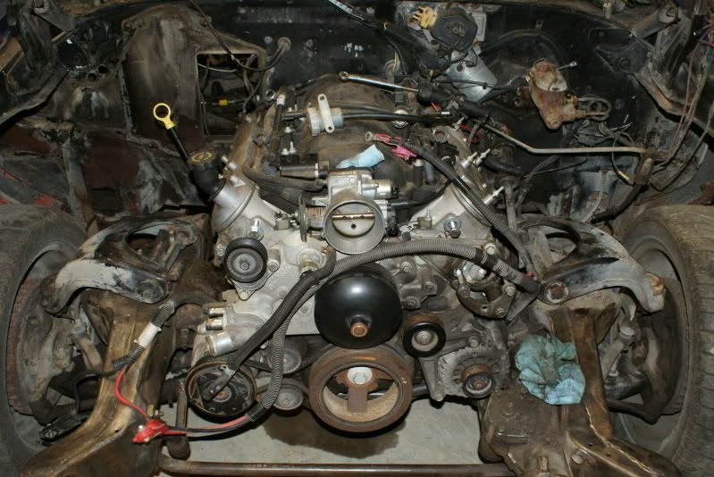
I fitted the motor mounts and adapters to the new engine and went for trial fit #1... It's a tight fit!
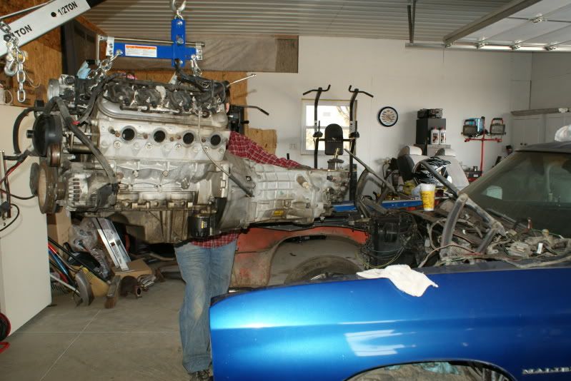
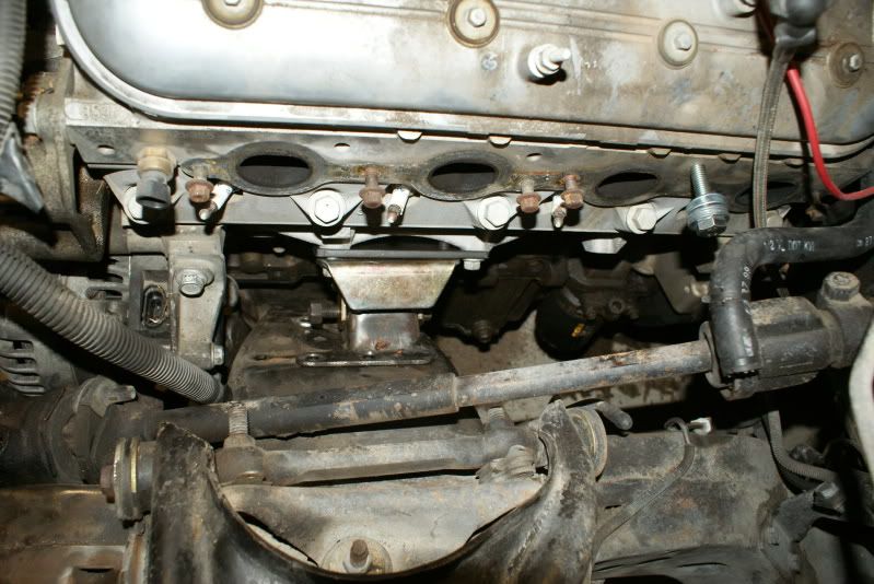
I wasn't able to get the engine fully in place. I tried with the engine/tranny sitting fairly level, and I also tried with the tranny tilted down quite a bit. The pictures below show it with the tranny tilted down.
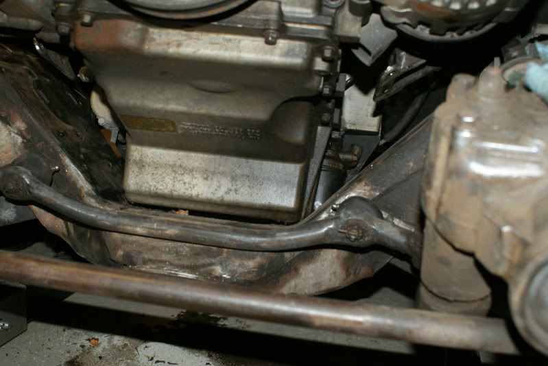
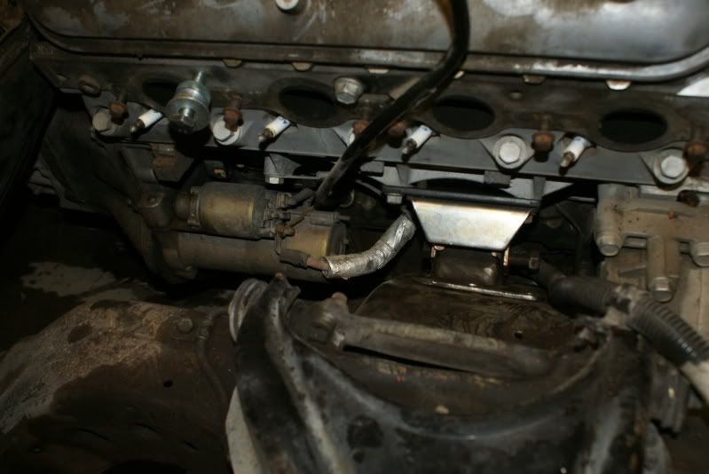
In the pic below, you can see how the oil pan is contacting the engine crossmember, preventing the engine/tranny from dropping down any lower. It looks like the engine would have to move backward around 2" or a little more before it would let the oil pan drop behind the crossmember.
The passenger-side valve cover is contacting the A/C box, and the chain that I'm hoisting the engine with is also contacting the firewall. I'm going to go ahead and remove the A/C box, but I think that will only gain me an inch or so. What about the chain -- have you guys been using some different holes on the engine to lift from, rather than the ones on the back end of the cylinder heads?
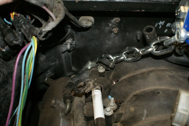
Any suggestions on how to get this thing in place? A long prybar and a big hammer?
I fitted the motor mounts and adapters to the new engine and went for trial fit #1... It's a tight fit!
I wasn't able to get the engine fully in place. I tried with the engine/tranny sitting fairly level, and I also tried with the tranny tilted down quite a bit. The pictures below show it with the tranny tilted down.
In the pic below, you can see how the oil pan is contacting the engine crossmember, preventing the engine/tranny from dropping down any lower. It looks like the engine would have to move backward around 2" or a little more before it would let the oil pan drop behind the crossmember.
The passenger-side valve cover is contacting the A/C box, and the chain that I'm hoisting the engine with is also contacting the firewall. I'm going to go ahead and remove the A/C box, but I think that will only gain me an inch or so. What about the chain -- have you guys been using some different holes on the engine to lift from, rather than the ones on the back end of the cylinder heads?
Any suggestions on how to get this thing in place? A long prybar and a big hammer?
Last edited by kst8engineer; 03-14-2009 at 11:26 PM. Reason: added to post
 03-17-2009, 10:08 AM
#54
The lsx engines are a bit taller from pan to valvecover than an sbc. I ran into the same issue when trying to install my 6.0L/4L80E. You can install the engine by itself then install the trans from below, but from what I hear the t56 requires the trans tunnel to be raised. Not sure if there is any way around that if you want it to fit and your driveline angles to be correct.
03-17-2009, 12:20 PM
#55
On The Tree
Thread Starter
iTrader: (6)
Join Date: Mar 2006
Location: Kansas
Posts: 192
Likes: 0
Received 0 Likes
on
0 Posts
The lsx engines are a bit taller from pan to valvecover than an sbc. I ran into the same issue when trying to install my 6.0L/4L80E. You can install the engine by itself then install the trans from below, but from what I hear the t56 requires the trans tunnel to be raised. Not sure if there is any way around that if you want it to fit and your driveline angles to be correct.
The key difference between my setup and the current BRP kit is that I'm running the factory F-body pan rather than the LH8 pan. Because of that, my engine/tranny have to move further rearward before the pan can drop down behind the crossmember. Has anybody successfully used the F-body pan with the t-cut (rather than cutting out the whole tunnel)?
03-17-2009, 03:13 PM
#56
On The Tree
Thread Starter
iTrader: (6)
Join Date: Mar 2006
Location: Kansas
Posts: 192
Likes: 0
Received 0 Likes
on
0 Posts
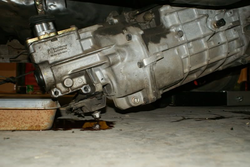
I'm in the middle of a 2nd trial fit right now. I extended the t-cut further toward the firewall, removed the shifter housing on top of the tranny, and I'm going in with the engine and tranny more level than I was before. I think removing the shifter housing and keeping the engine and tranny fairly level are two of the key factors to making it work.
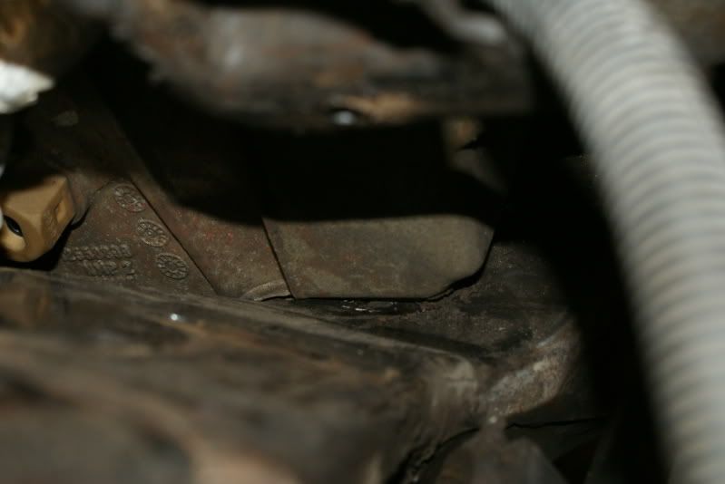
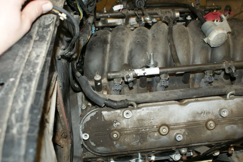
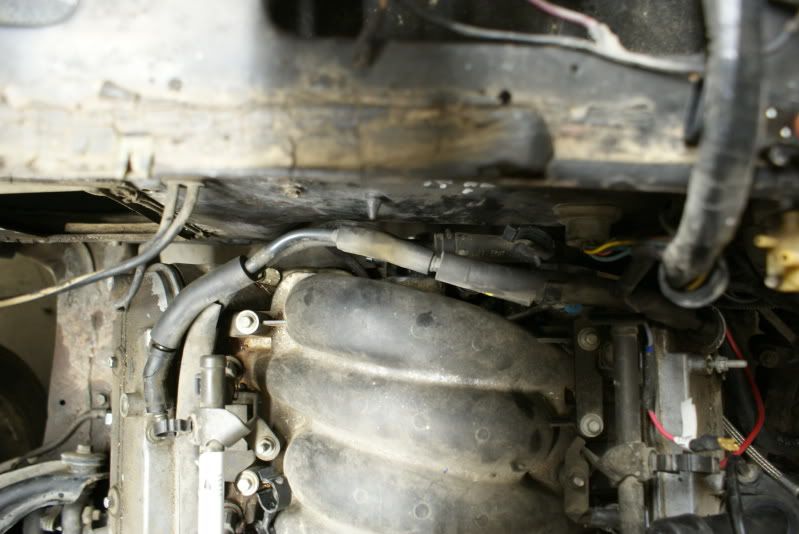
The engine is considerably closer to "falling into place" than it had been previously, but I'm still not quite there. I think the only thing preventing it from going into place now is the MAP sensor on the back of the intake manifold. The MAP sensor is hitting the firewall, just above the recessed area. If the engine was a little lower, I think it would clear OK, but it can't go down until it goes back another 1/2" or so. I've wondered about removing the MAP sensor and reinstalling it after the engine is in place, but I don't know if I'd have enough room to do that after installation or not.
The engine is considerably closer to "falling into place" than it had been previously, but I'm still not quite there. I think the only thing preventing it from going into place now is the MAP sensor on the back of the intake manifold. The MAP sensor is hitting the firewall, just above the recessed area. If the engine was a little lower, I think it would clear OK, but it can't go down until it goes back another 1/2" or so. I've wondered about removing the MAP sensor and reinstalling it after the engine is in place, but I don't know if I'd have enough room to do that after installation or not.
03-17-2009, 09:42 PM
#57
On The Tree
Thread Starter
iTrader: (6)
Join Date: Mar 2006
Location: Kansas
Posts: 192
Likes: 0
Received 0 Likes
on
0 Posts
I finally finished up trial fit #2 today. In addition to extending the t-cut and keeping the engine/tranny more level, I also ended up removing the MAP sensor. That was the ticket -- once the MAP sensor was removed, the engine fell into place. The downside is that I busted the little tang off of the piece on the back of the intake that retains the MAP sensor prior to figuring this out...
So, here are the lessons learned for future swappers using the f-body pan in an A-body:
1) A t-cut is necessary. I basically extended mine up to where the tunnel transitions to the firewall.
2) Rather than fastening your hoist chain to the threaded holes in the back of the cylinder heads, I used the holes slightly forward and above the exhaust primaries for cylinders 7 and 8. This frees up a little clearance between the heads and the firewall. I spaced the chain out away from the head with washers to prevent the chain from damaging the edge of the valve covers. In the pictures, you can see the bolts and washers still in the holes I'm referring to.
3) Don't try to take the engine and tranny in at much of an angle. They need to remain fairly flat in order to allow the oil pan to go past the crossmember and fall into place.
4) Remove the shifter housing from the top of the tranny. I think this was one of the keys to making it work. Under the small rubber boot, there are 4 allen-head screws that hold a cover plate on. Don't remove these. An inch or so lower are 4 hex-head screws (13 mm head if I remember correctly). Remove these instead and take the whole shifter off. Before I removed this, I was forced to maintain a steeper engine/tranny angle, and it wouldn't allow the bottom of the pan to move far enough rearward to clear the crossmember.
5) Remove the MAP sensor ahead of time! There's enough room to reinstall it after the engine is in place.
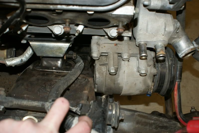
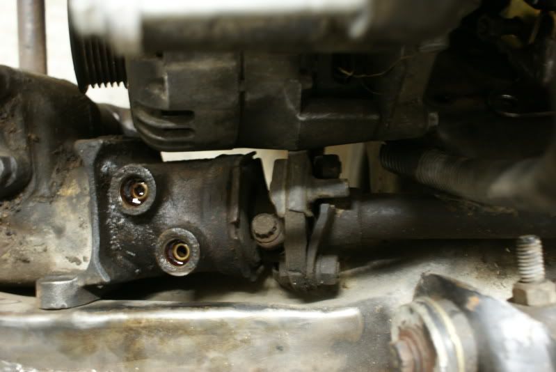
I haven't had a chance to really play with shifting the engine around much yet or checking clearances in detail. I know I've got basically zero clearance between the steering box and alternator, between the alternator and the steering rag joint, and between the A/C compressor and the crossmember. At a quick glance, I think oil pan to crossmember clearance appears to be OK.
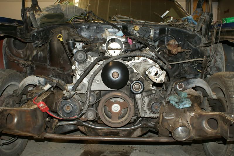
It's nice to see it sitting in place, at least I know it's possible to squeeze it into place now!
So, here are the lessons learned for future swappers using the f-body pan in an A-body:
1) A t-cut is necessary. I basically extended mine up to where the tunnel transitions to the firewall.
2) Rather than fastening your hoist chain to the threaded holes in the back of the cylinder heads, I used the holes slightly forward and above the exhaust primaries for cylinders 7 and 8. This frees up a little clearance between the heads and the firewall. I spaced the chain out away from the head with washers to prevent the chain from damaging the edge of the valve covers. In the pictures, you can see the bolts and washers still in the holes I'm referring to.
3) Don't try to take the engine and tranny in at much of an angle. They need to remain fairly flat in order to allow the oil pan to go past the crossmember and fall into place.
4) Remove the shifter housing from the top of the tranny. I think this was one of the keys to making it work. Under the small rubber boot, there are 4 allen-head screws that hold a cover plate on. Don't remove these. An inch or so lower are 4 hex-head screws (13 mm head if I remember correctly). Remove these instead and take the whole shifter off. Before I removed this, I was forced to maintain a steeper engine/tranny angle, and it wouldn't allow the bottom of the pan to move far enough rearward to clear the crossmember.
5) Remove the MAP sensor ahead of time! There's enough room to reinstall it after the engine is in place.
I haven't had a chance to really play with shifting the engine around much yet or checking clearances in detail. I know I've got basically zero clearance between the steering box and alternator, between the alternator and the steering rag joint, and between the A/C compressor and the crossmember. At a quick glance, I think oil pan to crossmember clearance appears to be OK.
It's nice to see it sitting in place, at least I know it's possible to squeeze it into place now!
03-17-2009, 10:00 PM
#58
TECH Resident
iTrader: (3)

Join Date: Sep 2005
Location: Edmond, Oklahoma
Posts: 796
Likes: 0
Received 0 Likes
on
0 Posts
My suggestion for the steering box would be to grind on it thats what I did. you can actually take quite a bit away I did more than necessary on my stock box just to see if I would strike oil and I didn't. Also good tips on stabbing the engine I am sure alot of people could use that info. As far as the AC goes I can't help you much other than to say looks like you may have to notch the crossmember or re-locate the AC.
 03-17-2009, 10:21 PM
#60
On The Tree
Thread Starter
iTrader: (6)
Join Date: Mar 2006
Location: Kansas
Posts: 192
Likes: 0
Received 0 Likes
on
0 Posts
My suggestion for the steering box would be to grind on it thats what I did. you can actually take quite a bit away I did more than necessary on my stock box just to see if I would strike oil and I didn't. Also good tips on stabbing the engine I am sure alot of people could use that info. As far as the AC goes I can't help you much other than to say looks like you may have to notch the crossmember or re-locate the AC.