
My wiring harness build thread
 03-18-2011, 12:38 PM
#1

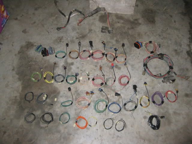
In the pics to follow, I'll show my attempts to save some money by building my own wiring harness. Pocket already did an excellent thread, and I've studied it several times.
I'm putting an '01 LM7 and a 4L60E into an '85 Nissan 300ZX.
My PCM is from an '02 Yukon 2WD L59.
Some of the wires and connectors came with my LM7 and my LQ4, but some are from a '96 Astro I parted out last spring.
I also referred to www.lt1swap.com for pin-outs, wire colors, et cetera.

I thought this would be a good start.

This is what LKQ sent me for my $90.
I'm putting an '01 LM7 and a 4L60E into an '85 Nissan 300ZX.
My PCM is from an '02 Yukon 2WD L59.
Some of the wires and connectors came with my LM7 and my LQ4, but some are from a '96 Astro I parted out last spring.
I also referred to www.lt1swap.com for pin-outs, wire colors, et cetera.
I thought this would be a good start.
This is what LKQ sent me for my $90.


Trending Topics


 03-18-2011, 10:23 PM
#14
Teching In
iTrader: (2)

Join Date: Aug 2008
Location: phoenix
Posts: 13
Likes: 0
Received 0 Likes
on
0 Posts
this is turning out nice it is going to help a lot of people. I just did the wiring harness for my 2002 lm7 thats going into my nova. I used the lt1swap site. The only thing i can say is that site is great.

 03-19-2011, 08:07 AM
#16

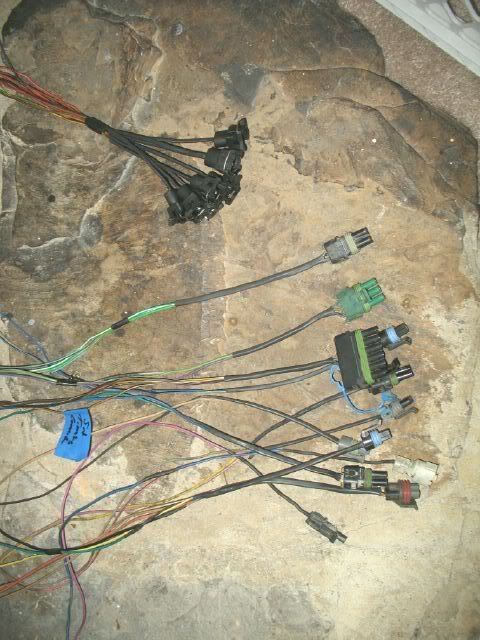
As I demo spare harnesses or prep them for custom routing, I label their ecm pin locations, remove the pins from the ecm connector, pull the complete wire with end connector from the harness, and then coil them up for storage.
Then when it comes time to lay the harness out, just start 1 sensor at a time, connect the required wire loop to the sensor, route the remaining portion of the wire where you want it, lengthen if necessary and let the wires bundle up where the ecm will be placed. Once the engine side it done, then either shorten the wires at the ECM or cut and repin them.
I also like to shrink wrap the first 4-6" of wire from the connector to clean up the look of the install.
 03-19-2011, 09:50 AM
#17
I made a bit of progress.

the black wire has too much solder, while the blue has not enough. The gray is about right.
I need to get more sleeves.

and

My harness work may not agree with pocket or fieroguru, but since it'll all be hidden in the corrugated conduit, so what? It'll look very presentable. Mine's safe and affordable, and I can't be the only LSx swapper who isn't a pin-changing enthusiast. Especially since this particular swap project doesn't require all that extra, un-necessary work.
Also, when cutting connectors off wires, if you leave about an inch, that leaves more wire for extending whatever you need the wire for. Leaving 6 inches or a foot is a waste of good wire.
I prefer to only have 2 soldered joints between the PCM and the sensor, so the extension wire needs to be long enough, and most donor harnesses don't have more than 1 long wire of any particular color or pair of colors.
All those '80s connectors will be thrown away soon, anyway.
Some of the connectors you may get with your engine may have less than an inch of wire on them, anyway. If you live in BFE, 1/2" is still good enough. Pretty? No. But adequate, YES!
the black wire has too much solder, while the blue has not enough. The gray is about right.
I need to get more sleeves.
and
My harness work may not agree with pocket or fieroguru, but since it'll all be hidden in the corrugated conduit, so what? It'll look very presentable. Mine's safe and affordable, and I can't be the only LSx swapper who isn't a pin-changing enthusiast. Especially since this particular swap project doesn't require all that extra, un-necessary work.
Also, when cutting connectors off wires, if you leave about an inch, that leaves more wire for extending whatever you need the wire for. Leaving 6 inches or a foot is a waste of good wire.
I prefer to only have 2 soldered joints between the PCM and the sensor, so the extension wire needs to be long enough, and most donor harnesses don't have more than 1 long wire of any particular color or pair of colors.
All those '80s connectors will be thrown away soon, anyway.
Some of the connectors you may get with your engine may have less than an inch of wire on them, anyway. If you live in BFE, 1/2" is still good enough. Pretty? No. But adequate, YES!
Last edited by Isolde; 03-19-2011 at 10:14 AM.
03-19-2011, 10:08 AM
#18
This is a waste of expensive shrink wrap, plus if you study stock GM harnesses, you'll see they run the corrugated conduit to within an inch of the connector, so none of this wrapping should be visible, anyway. Plus with the wrap on there, you can't see which wire is which color when doing troubleshooting on the side of the road. So the wrap shouldn't go snug up against the connector.
03-19-2011, 11:35 AM
#19
This is a waste of expensive shrink wrap, plus if you study stock GM harnesses, you'll see they run the corrugated conduit to within an inch of the connector, so none of this wrapping should be visible, anyway. Plus with the wrap on there, you can't see which wire is which color when doing troubleshooting on the side of the road. So the wrap shouldn't go snug up against the connector.
03-19-2011, 12:31 PM
#20
Teching In
Join Date: Aug 2005
Location: Indianapolis
Posts: 4
Likes: 0
Received 0 Likes
on
0 Posts
>>>Plus with the wrap on there, you can't see which wire is which color when doing troubleshooting on the side of the road.>>>
While we applaud your attempt to tackle this large project, these people are trying to help you improve your assembly methods.
The idea is to build something that doesn’t stop along the side of the road.
Some of these recommendations will help you to prevent this from occurring.
Good Luck -
While we applaud your attempt to tackle this large project, these people are trying to help you improve your assembly methods.
The idea is to build something that doesn’t stop along the side of the road.
Some of these recommendations will help you to prevent this from occurring.
Good Luck -