

88 Fiero Formula LS4/F40 6 speed swap


 09-29-2012, 07:05 PM
#25

I am keeping the AFM feature mostly to see if I can make it work. This isn't a max effort build, more of an all around performer and I would love to see 30+ mpg on the interstate. The concern I have is how harsh the engage/disengage will be with a clutch. If it is too much, I will ditch AFM and get a cam speced for my setup.
Thanks!
Thanks!
I will have more pictures/updates posted on Sunday.
09-30-2012, 08:50 AM
#27
I wouldn't go that far, as I continue to learn and get better with time and practice. I don't do this for a living, so I tend to work at a slow pace and make sure I am happy with the overall look and function of the part. If I don't like it, I make another.
My machining/fabrication skills developed out of necessity. First, I focus on a single year of an obscure model (88 Fiero), so there are not many aftermarket parts to buy off the shelf. Second, with a wife and 2 young girls, there isn't a whole lot of available $$$ to spend on this swap. So to keep costs at a minimum, I have fabricated/modified everything that was within my capabilities.
My machining/fabrication skills developed out of necessity. First, I focus on a single year of an obscure model (88 Fiero), so there are not many aftermarket parts to buy off the shelf. Second, with a wife and 2 young girls, there isn't a whole lot of available $$$ to spend on this swap. So to keep costs at a minimum, I have fabricated/modified everything that was within my capabilities.
The following users liked this post:
outlawtorn71 (09-19-2021)
 09-30-2012, 09:06 AM
#29
Moving back to the transmission side of things. The F40 is a Saab transmission, so I had to rework just about everything to mate it with fiero components. Here are all the details for the shifter, cables and tranmission mounted shifter bracket.
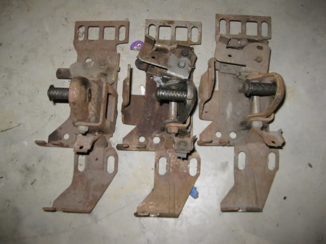
Back to the shelf and pulled off these shifters for parts. Two are 4 speed shifters (with each missing a part from the reverse lockout) and an isuzu.
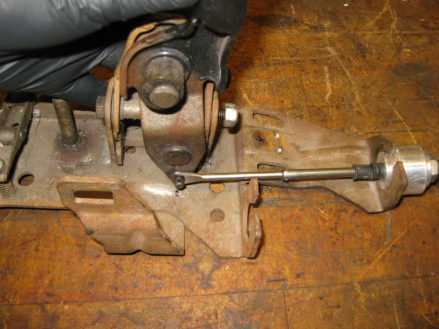
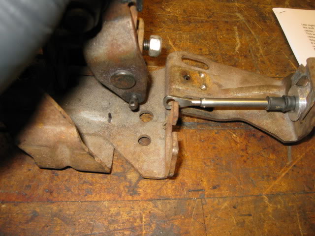
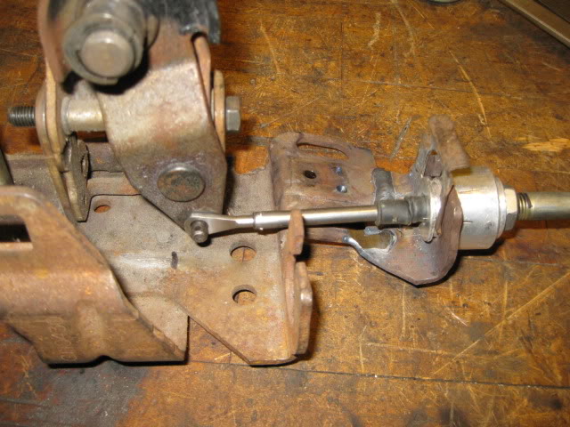
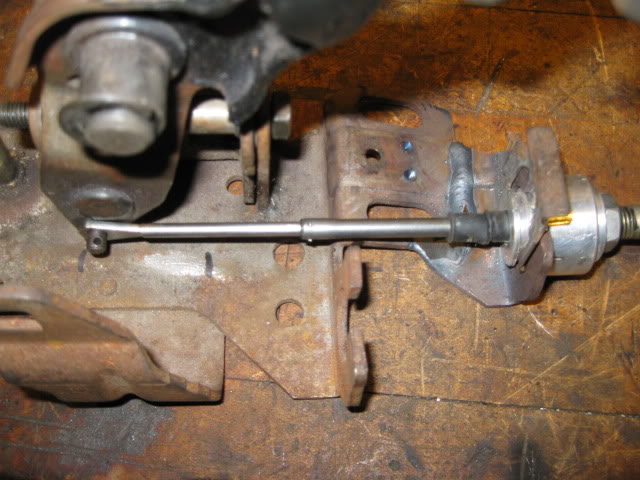
Tore one of the 4 speed shifters down and then installed my isuzu shifter lever and the old getrag select cable. With the cable in the stock 4 speed bracket, the shifter has very limited range. The first picture is with the cable fully extended and the 2nd one is with the shifter at is full range... there is about 1 5/8 gap:
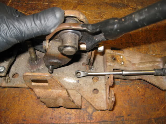
Going the other way with the cable fully collapsed vs. the shifter results in a 1" gap:
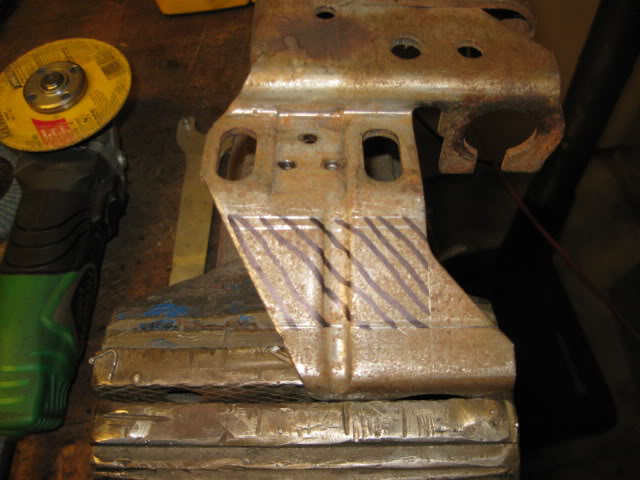
So the cable bracket needs to be moved forward. Anywhere between 1" and 1 5/8" probably would work, but I chose 1 5/16" to keep everything centered - that way I could build up the shifter stops to reduce cable abuse. Here is where I marked the section to remove:
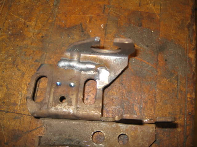
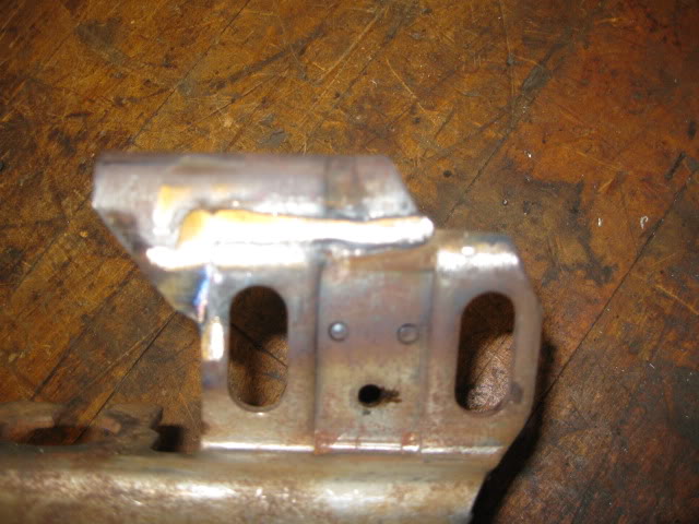
And welded back up with a range of motion checks:
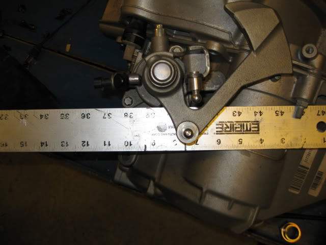
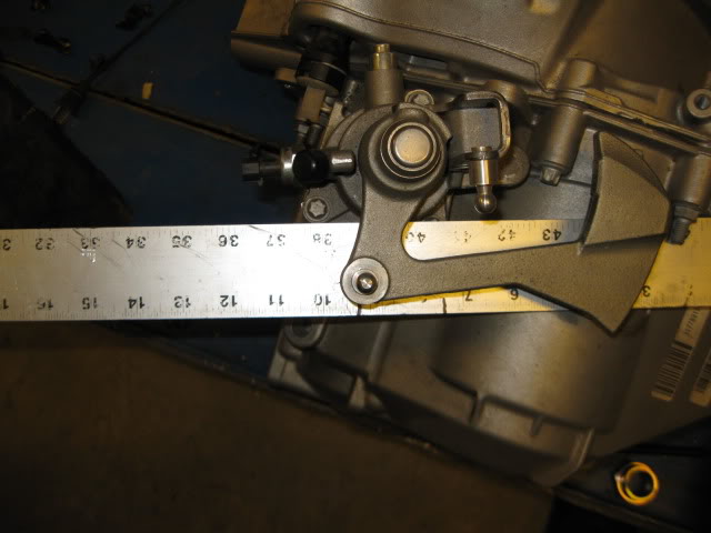
Since the Getrag Select cable only has 1 3/4" range of motion, I went and checked the needed range of motion on the F40 (the one for the 4.3) and got 1 3/4" as well, but I need to check it again in a more precise manner.
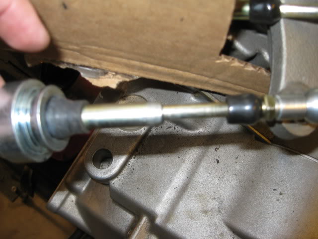
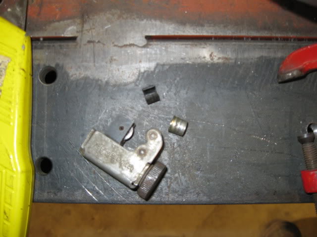
I started out with two new Getrag select cables. The cable that will become the shift cable was modified slightly to increase its stroke. Just took a tubing cutter and removed about 3/8" from the inner sleeve:
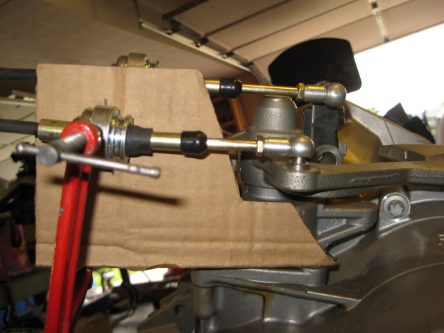
Then a card board mockup to get the general size/shape of the bracket and the approximate cable positions:
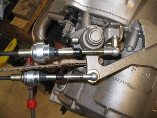
Transfer the card board pattern to some 1/8" steel, bent to shape and then use some 1 1/2" square stock, drilled some 1" holes for the cables (need to enlarge slightly more than 1") and then cut then into wedges. The round bodies of the cable ends needed about 1/8" removed (flattened so they would fit within the tubes). Then tack it all together and cut off the excess:
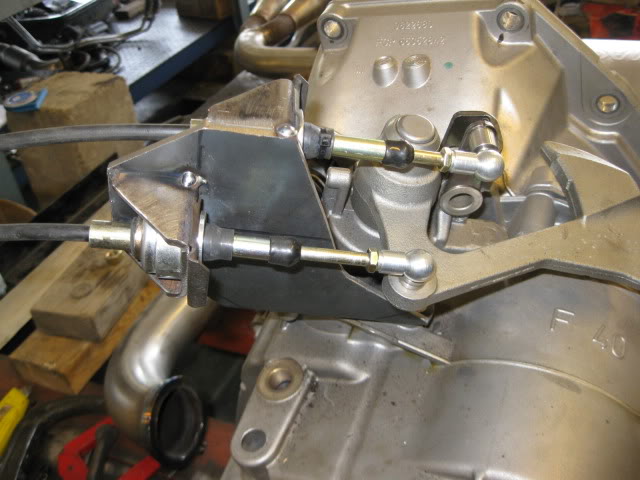
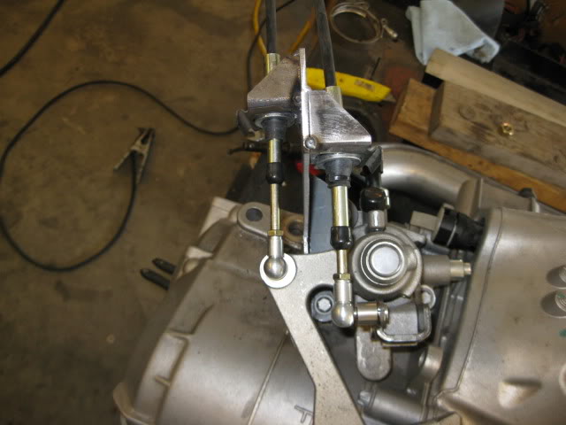
Everything works as it should. I modified the reverse lockout to make it easier to engage .
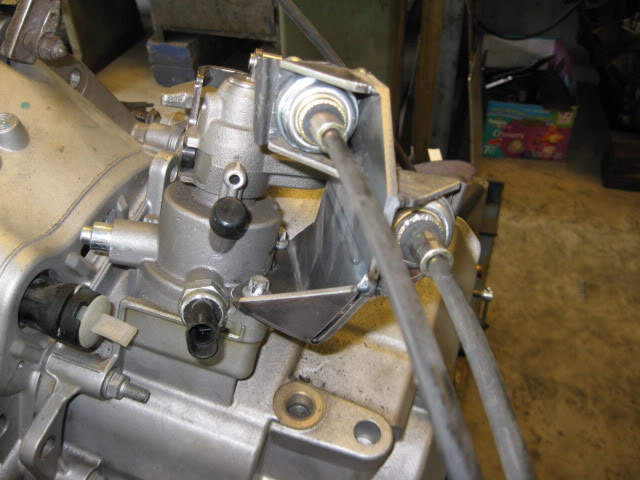
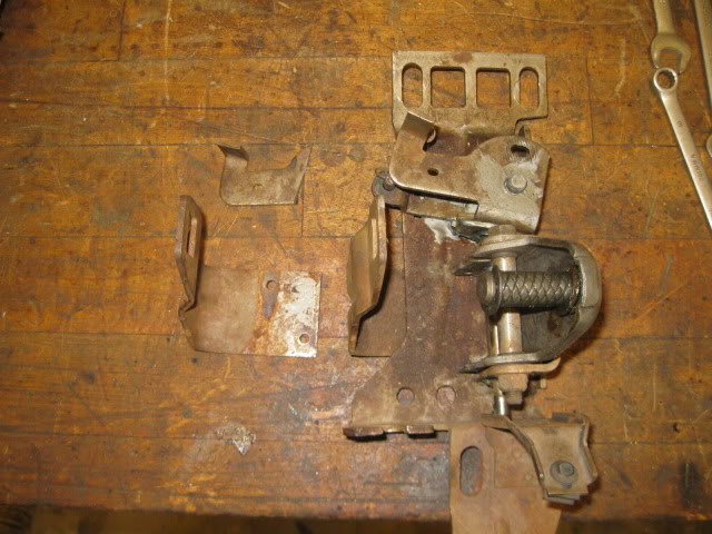
Here are a couple of the brackets for the console mounted reverse switch that I went ahead and removed:
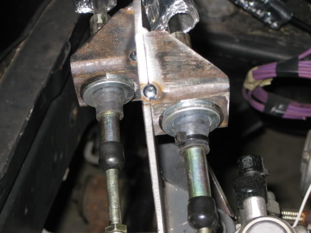
It is hard to see in the above pics, but I found some cleaner looking clips to hold the cable ends in place for under $4 from Tractor Supply (2 in a package):
Back to the shelf and pulled off these shifters for parts. Two are 4 speed shifters (with each missing a part from the reverse lockout) and an isuzu.
Tore one of the 4 speed shifters down and then installed my isuzu shifter lever and the old getrag select cable. With the cable in the stock 4 speed bracket, the shifter has very limited range. The first picture is with the cable fully extended and the 2nd one is with the shifter at is full range... there is about 1 5/8 gap:
Going the other way with the cable fully collapsed vs. the shifter results in a 1" gap:
So the cable bracket needs to be moved forward. Anywhere between 1" and 1 5/8" probably would work, but I chose 1 5/16" to keep everything centered - that way I could build up the shifter stops to reduce cable abuse. Here is where I marked the section to remove:
And welded back up with a range of motion checks:
Since the Getrag Select cable only has 1 3/4" range of motion, I went and checked the needed range of motion on the F40 (the one for the 4.3) and got 1 3/4" as well, but I need to check it again in a more precise manner.
I started out with two new Getrag select cables. The cable that will become the shift cable was modified slightly to increase its stroke. Just took a tubing cutter and removed about 3/8" from the inner sleeve:
Then a card board mockup to get the general size/shape of the bracket and the approximate cable positions:
Transfer the card board pattern to some 1/8" steel, bent to shape and then use some 1 1/2" square stock, drilled some 1" holes for the cables (need to enlarge slightly more than 1") and then cut then into wedges. The round bodies of the cable ends needed about 1/8" removed (flattened so they would fit within the tubes). Then tack it all together and cut off the excess:
Everything works as it should. I modified the reverse lockout to make it easier to engage .
Here are a couple of the brackets for the console mounted reverse switch that I went ahead and removed:
It is hard to see in the above pics, but I found some cleaner looking clips to hold the cable ends in place for under $4 from Tractor Supply (2 in a package):
09-30-2012, 09:44 AM
#30
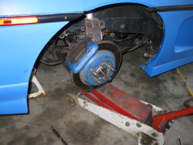
The axles were the next challenge. Since most axle failures on high powered fieros are either the actual axle shaft or the outer CV assembly, I wanted to run an off the shelf GM axle, so when I break one, it is easy/low cost to replace.
With the F40 being a Saab transmission, none of the individual components of the axle swap between the F40 axle and a fiero type axle except the for the outer CV star. So I used an idea from another fiero enthusiast and made a hybrid tripod for the driver side. I used the spline portion for the F40 and the tripod cup (and rest of the axle for that matter) from a 96 Corsica (PS from 4T60) which is the shortest GM axle shaft.
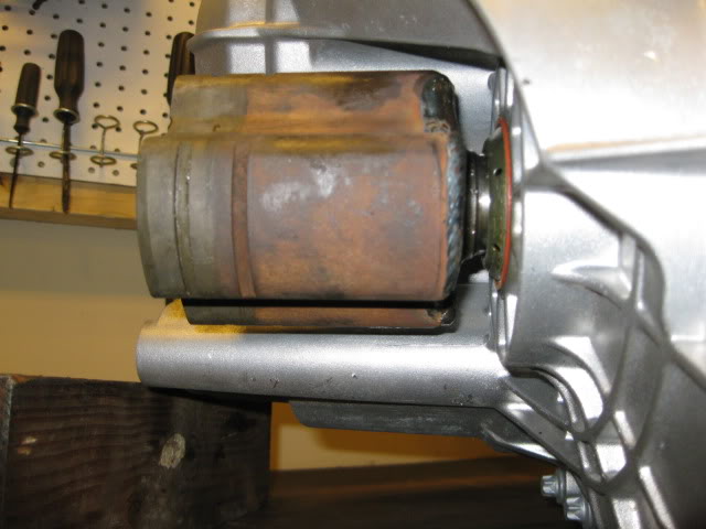
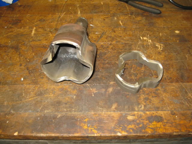
Upon test fitting the DS corsica axle, I noticed the tripod cage was too long and not allowing full axle articulation.
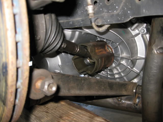
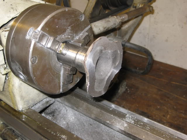
To fix this issue, I cut the outer set of CV boot grooves off and will use the inside ones instead (boot only uses 1 set).
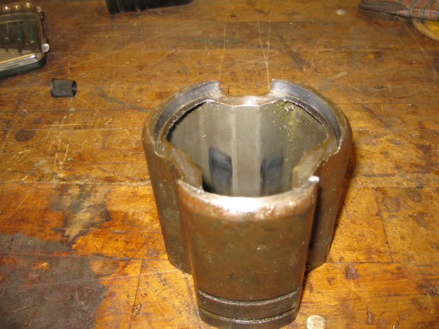
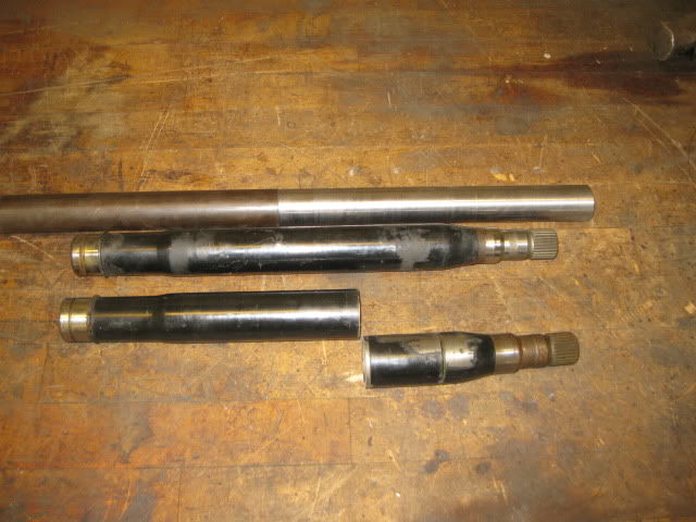
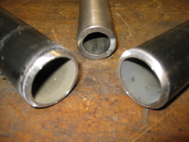
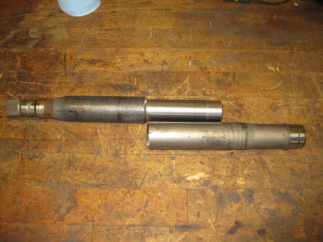
The passenger side axle was next. This side was a little more complicated in that it has an intermediate shaft and bearing support. Upon initial mockup, I found that the stock F40 axle was too short and that the CV proximity to the engine block would not allow using a larger hybrid tripod. So I picked up 2 Saab intermediate shafts, since they are hollow in the center, I could cut two, sleeve them and make a longer intermediate shaft so I could used the G6 axle (and just swap out the outer CV since the CV Star is the same as the fiero).
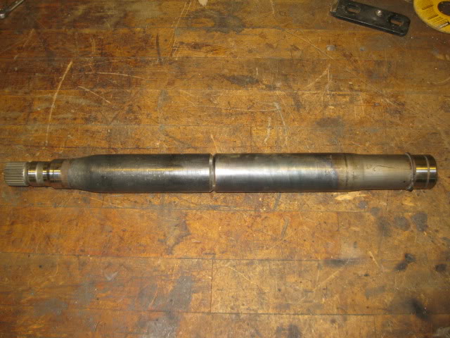
The inner sleeve was 1 1/2" 1/2" wall DOM material. It needed turned down to about 1.45". I moved the cut on the first intermediate shaft to place the seam closer to the center on the final product (and to make room for the inner sleeve to extend about 5-6" past the seam). Also located the cut line on the second intermediate shaft to increase the total length. The edges of both intermediate halves were beveled as well for good weld penetration (and I do not need to worry about blowing out the back side since the sleeve will be there).
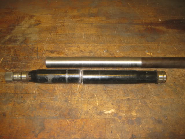
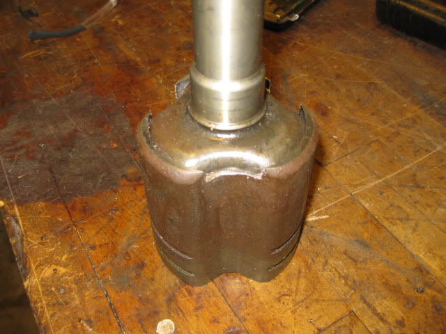
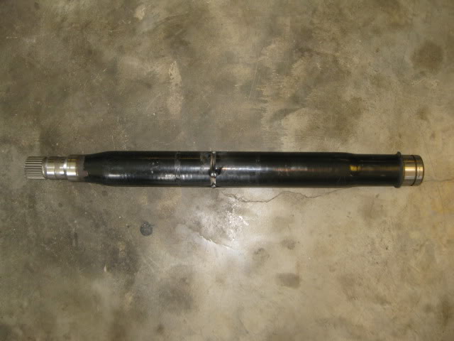
Tacked the two parts of the intermediate shaft together and then put the engine/tranny/cradle back into the fiero to confirm the final length of the intermediate shaft.
Before I could confirm the axle length, I had to swap out the G6 CV with a fiero CV:
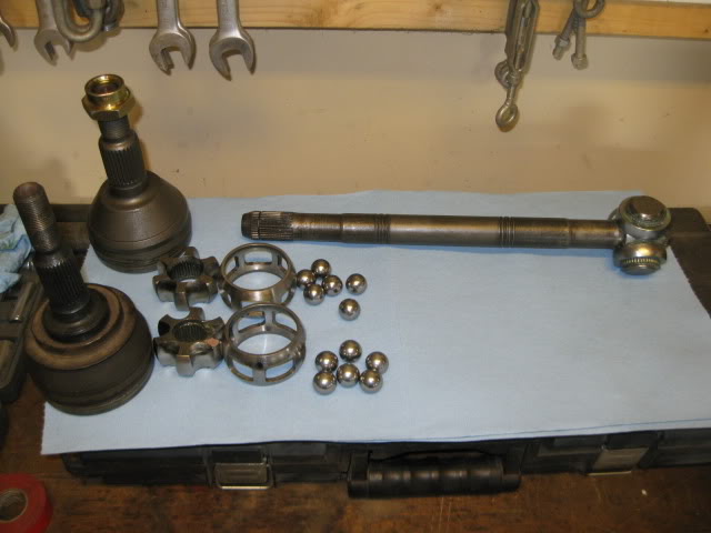
Then I put the PS rear suspension on and leveled the lateral links to check the placement of the tripod rollers in the tripod cage. There was 3/8" of clearance before the rollers were bottomed out and with the rollers bottomed out there was 1 1/2" from the edge of the rollers to the edge of the tripod cage. So shortening the intermediate shaft by 3/8" will center the tripod rollers in the tripod cage at "stock" ride height.
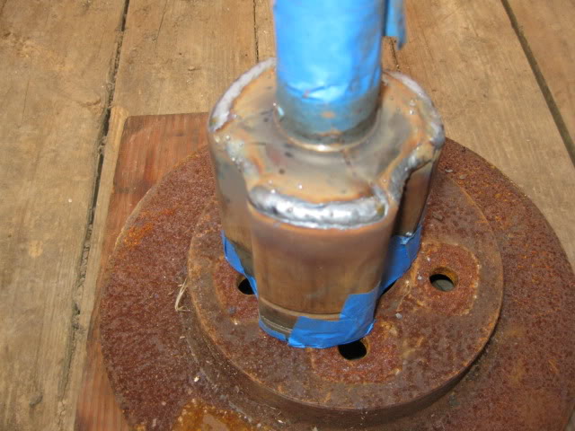
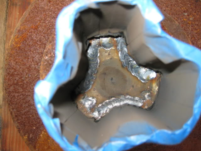
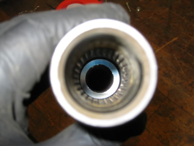
Time to press in the inner sleeve (took a 20 ton press).
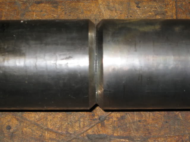
While welding. I built up the area around the seam and enlarged the OD about 1/4" and then turned it down smooth about 1/8" thicker at the seam. This should help ensure the welded seam is at least as thick as the original tube thickness.
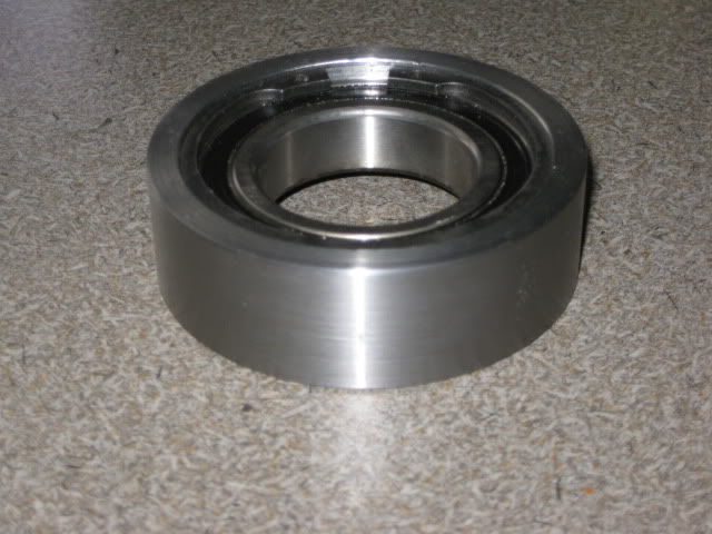
Here I made the bearing holder for the intermediate shaft. The ring is 1/4" thick around the bearing and had a machined lip on one side and a snap ring groove on the other. Now I can weld this bearing holder to the rest of the bracket.
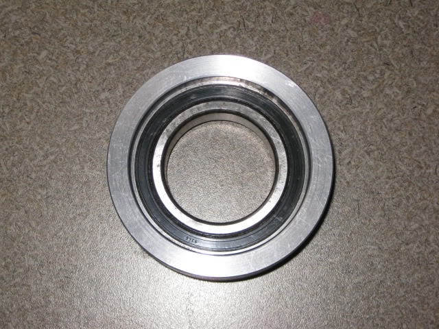
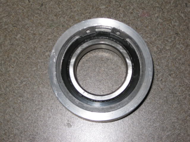
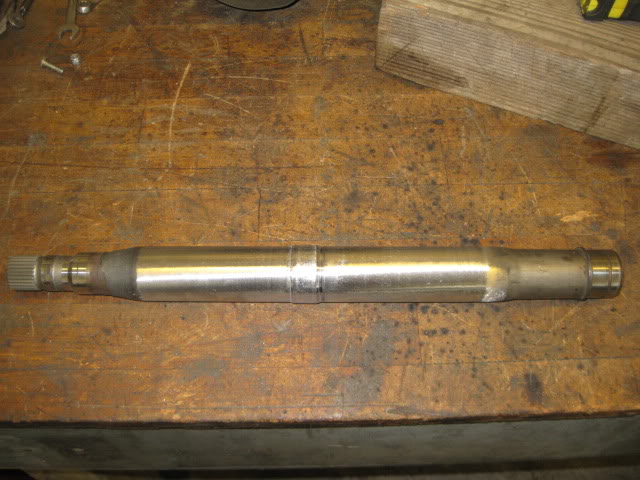
Intermediate shaft bearing holder is now complete and now I can use the F40 axle on the passenger side:
With the F40 being a Saab transmission, none of the individual components of the axle swap between the F40 axle and a fiero type axle except the for the outer CV star. So I used an idea from another fiero enthusiast and made a hybrid tripod for the driver side. I used the spline portion for the F40 and the tripod cup (and rest of the axle for that matter) from a 96 Corsica (PS from 4T60) which is the shortest GM axle shaft.
Upon test fitting the DS corsica axle, I noticed the tripod cage was too long and not allowing full axle articulation.
To fix this issue, I cut the outer set of CV boot grooves off and will use the inside ones instead (boot only uses 1 set).
The passenger side axle was next. This side was a little more complicated in that it has an intermediate shaft and bearing support. Upon initial mockup, I found that the stock F40 axle was too short and that the CV proximity to the engine block would not allow using a larger hybrid tripod. So I picked up 2 Saab intermediate shafts, since they are hollow in the center, I could cut two, sleeve them and make a longer intermediate shaft so I could used the G6 axle (and just swap out the outer CV since the CV Star is the same as the fiero).
The inner sleeve was 1 1/2" 1/2" wall DOM material. It needed turned down to about 1.45". I moved the cut on the first intermediate shaft to place the seam closer to the center on the final product (and to make room for the inner sleeve to extend about 5-6" past the seam). Also located the cut line on the second intermediate shaft to increase the total length. The edges of both intermediate halves were beveled as well for good weld penetration (and I do not need to worry about blowing out the back side since the sleeve will be there).
Tacked the two parts of the intermediate shaft together and then put the engine/tranny/cradle back into the fiero to confirm the final length of the intermediate shaft.
Before I could confirm the axle length, I had to swap out the G6 CV with a fiero CV:
Then I put the PS rear suspension on and leveled the lateral links to check the placement of the tripod rollers in the tripod cage. There was 3/8" of clearance before the rollers were bottomed out and with the rollers bottomed out there was 1 1/2" from the edge of the rollers to the edge of the tripod cage. So shortening the intermediate shaft by 3/8" will center the tripod rollers in the tripod cage at "stock" ride height.
Time to press in the inner sleeve (took a 20 ton press).
While welding. I built up the area around the seam and enlarged the OD about 1/4" and then turned it down smooth about 1/8" thicker at the seam. This should help ensure the welded seam is at least as thick as the original tube thickness.
Here I made the bearing holder for the intermediate shaft. The ring is 1/4" thick around the bearing and had a machined lip on one side and a snap ring groove on the other. Now I can weld this bearing holder to the rest of the bracket.
Intermediate shaft bearing holder is now complete and now I can use the F40 axle on the passenger side:
The following users liked this post:
LS4eva (09-17-2020)
09-30-2012, 09:59 AM
#32
Now it was time to start working on the chassis side of things. With all the mods to the cradle and water pump, the LS4/F40 combo would fit without any chassis modifications (besides removing the battery tray), but a few tweaks would make it fit better.
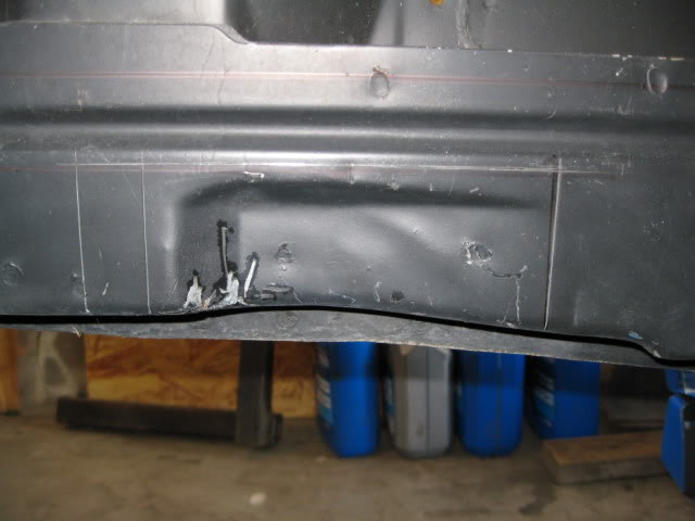
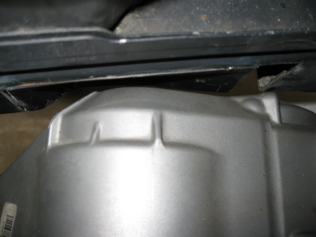
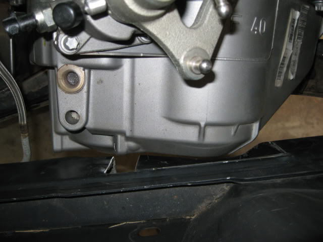
The test fit showed a couple of areas that needed some additional clearance. F40 transmission to the driver side frame rail has about 1/4" clearance to the factory notch in the frame and this is after I ground down the rib on the end of the transmission about 3/16”. Right now the notch isn't centered to the transmission and the tranny is very close to the edge of the notch... it would look better with the notch moved to the rear 1".
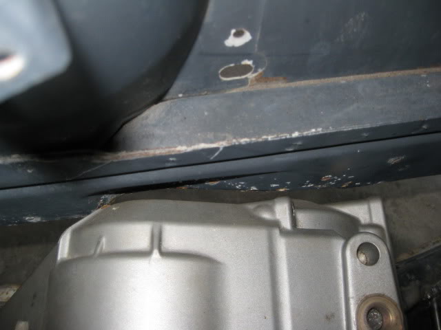
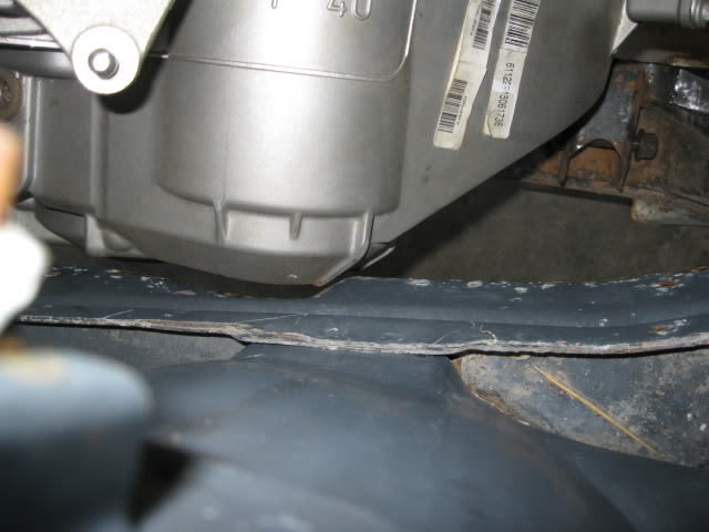
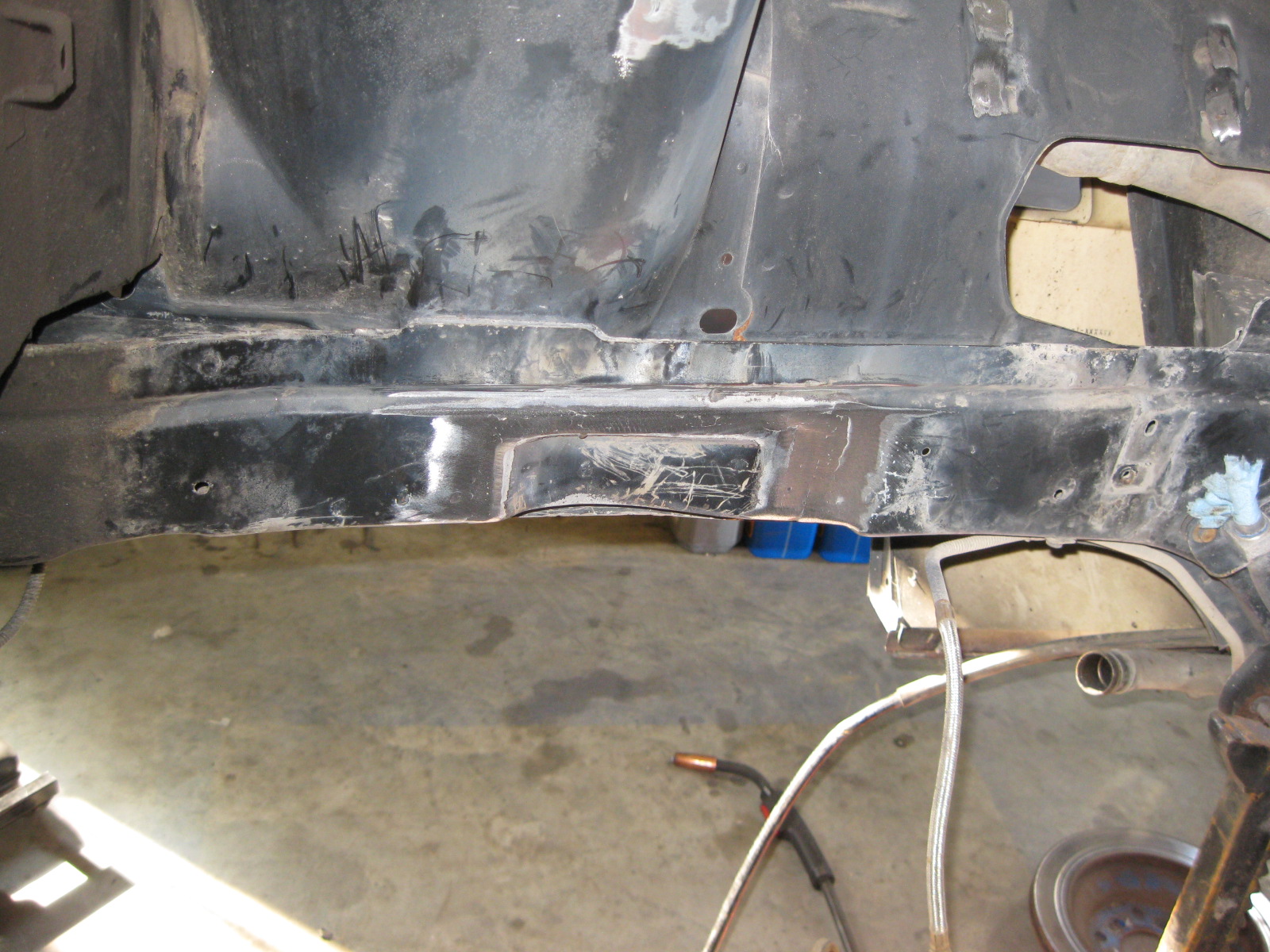
Moving the factory notch:
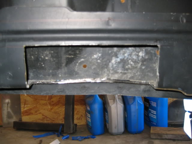
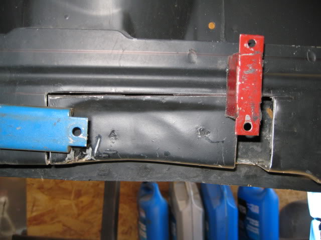
The relocated frame notch is going to workout just fine:
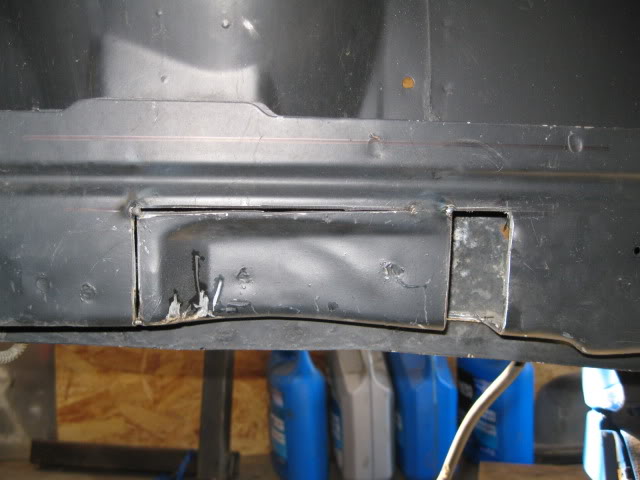
Welded in the relocated panel on the DS frame rail,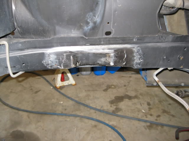
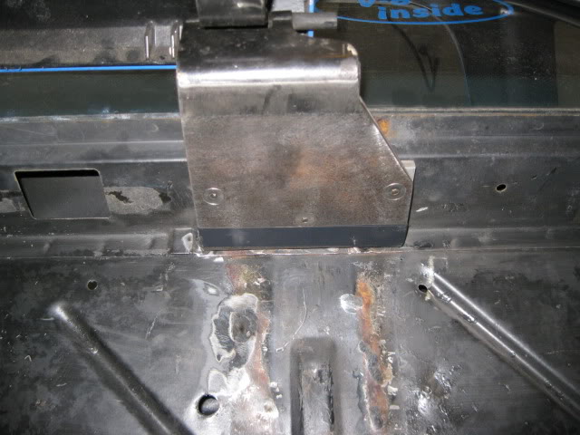
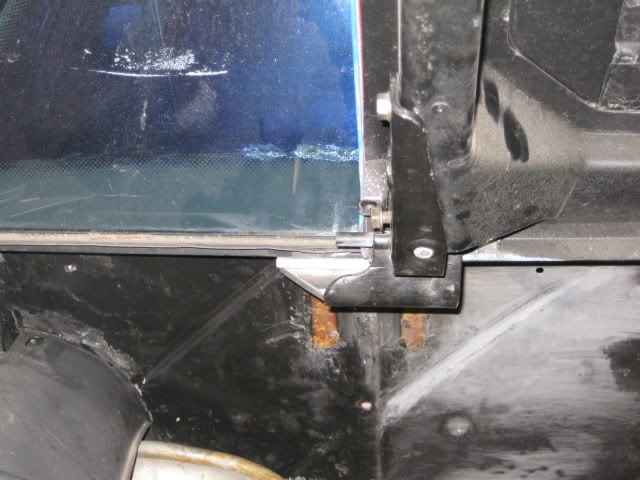
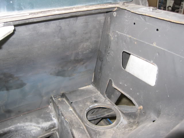
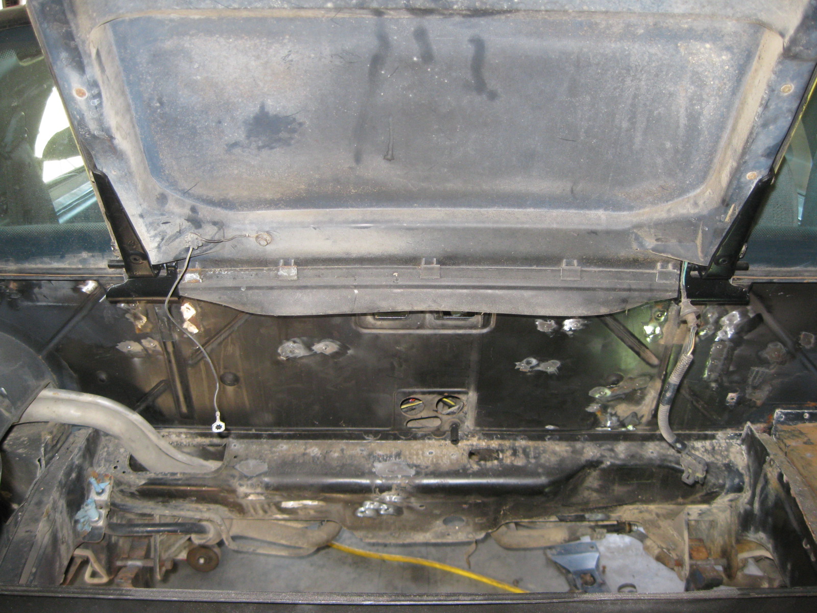
Here is the clearance to the decklid hinge box... but the water pump isn't on the engine. These things clutter up an otherwise clean firewall and so instead of cutting them back for clearance, I will just eliminate them entirely.
These hinge boxes clutter up an otherwise clean firewall and so instead of cutting them back for clearance, I will just eliminate them entirely.
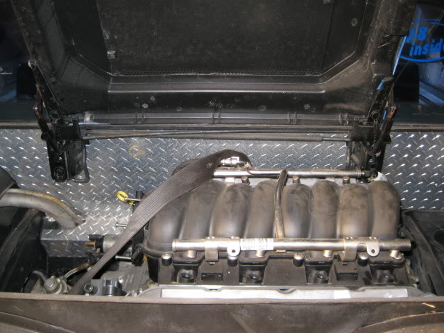
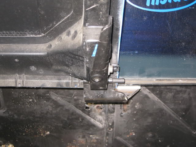
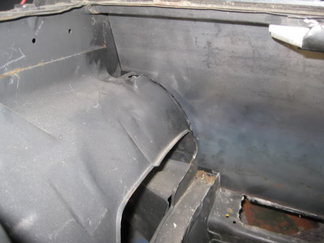
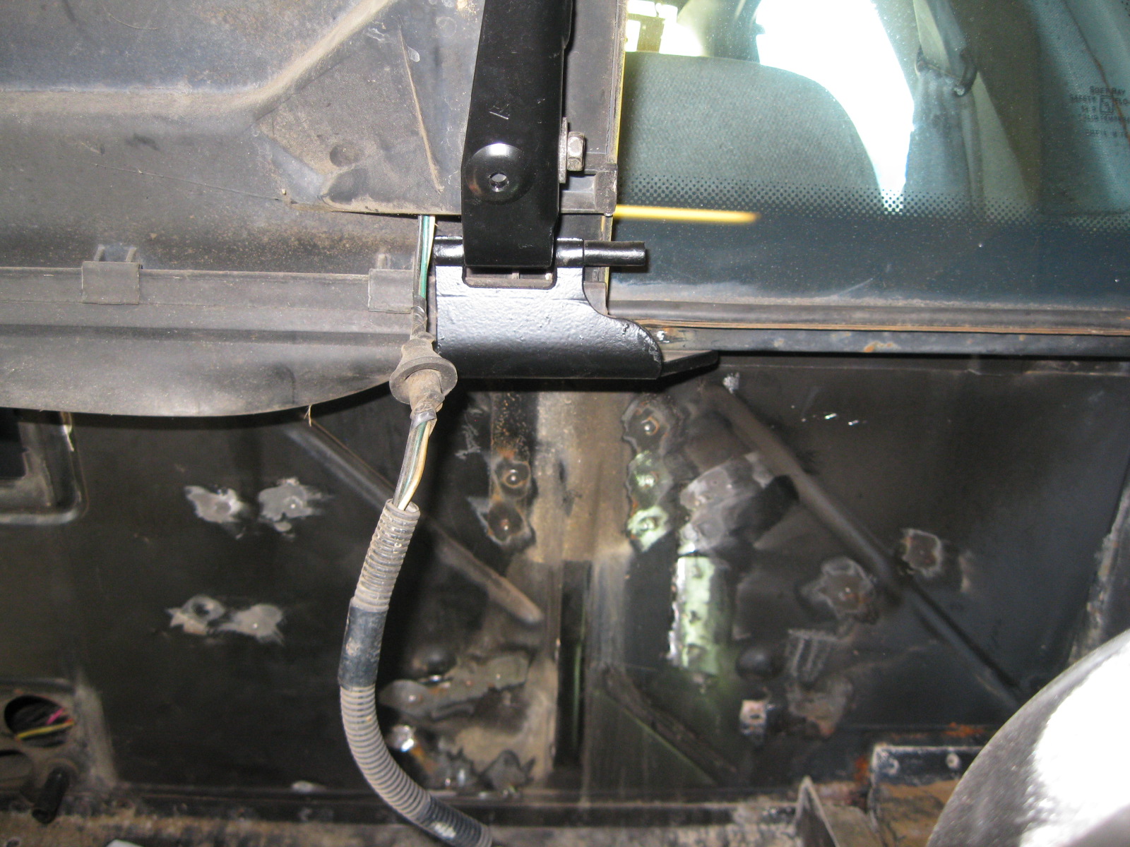
Here is an underside view of the factory hinge once the hinge box is removed:
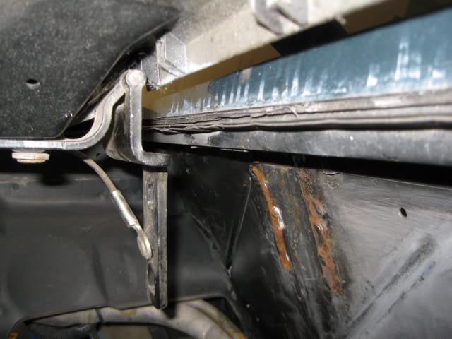
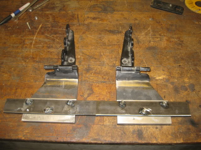
The plan is to cut the hinge off where it bends for the attachment to the stock hinge boxes. Then weld a piece of 1/4" steel to the hinge and have this plate bolted to the fiero chassis... something like this:
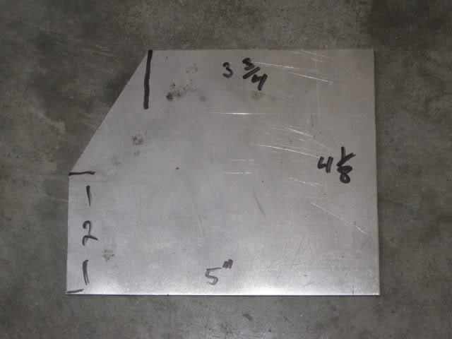
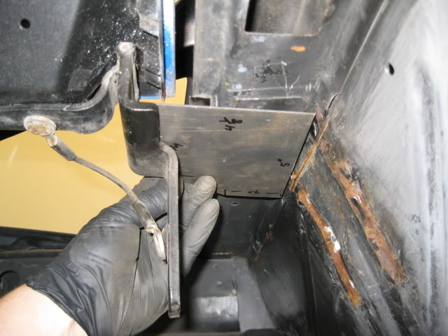
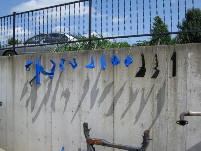
Here are the two modified hinges ready to be installed:
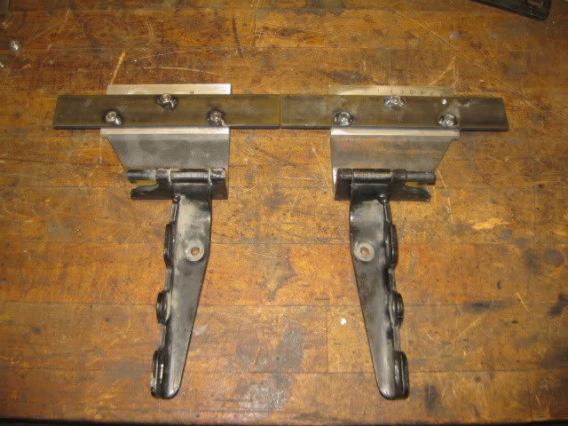
Hinges are pretty much done, I may reduce the 1/4" spacer to 1/8" to better line up the body line at the decklid vents:
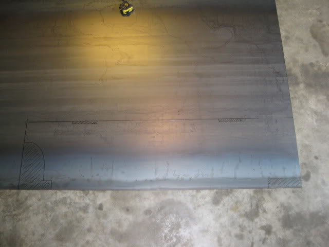
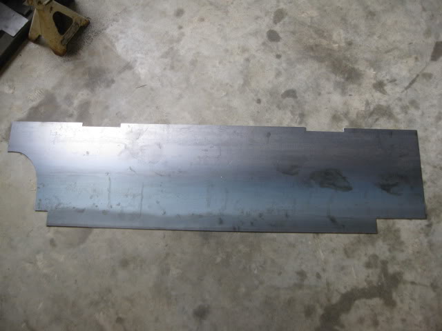
Creating a new smooth firewall panel:
Here is the template:
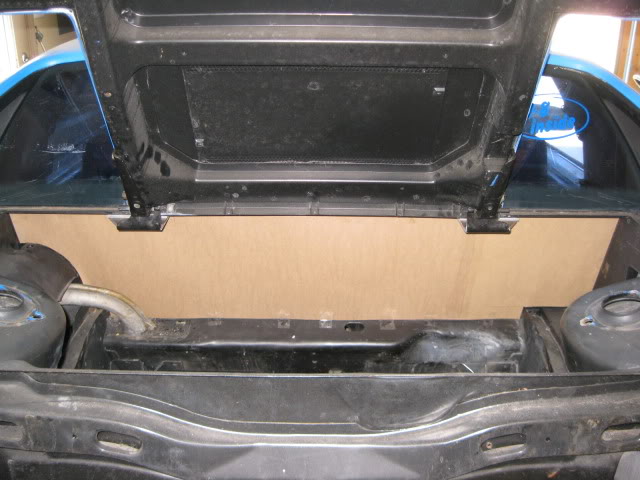
Transferred to the sheet sheet:
First test fit of the panel:
I have marked a few places where I can remove a little more material to even up the gaps and provide room for the panel to expand slightly.
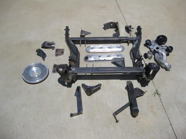
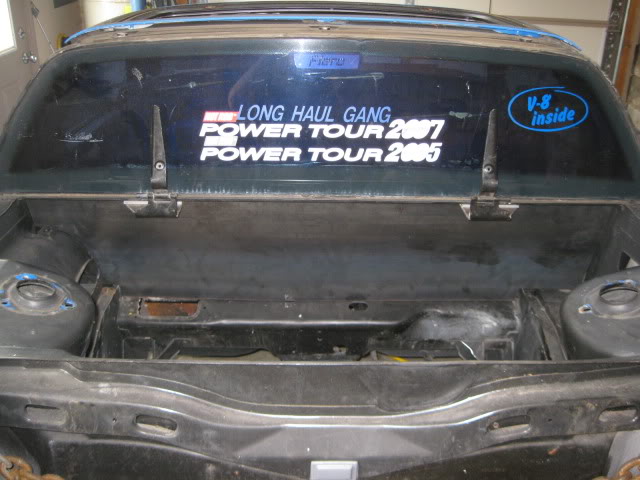
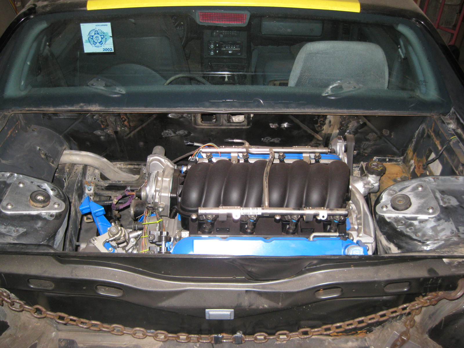
Now I decided to start actually working on the Black cars chassis and stop using the blue car for mock up. Here is what the engine bay looked like once the 2.8/Getrag was removed:
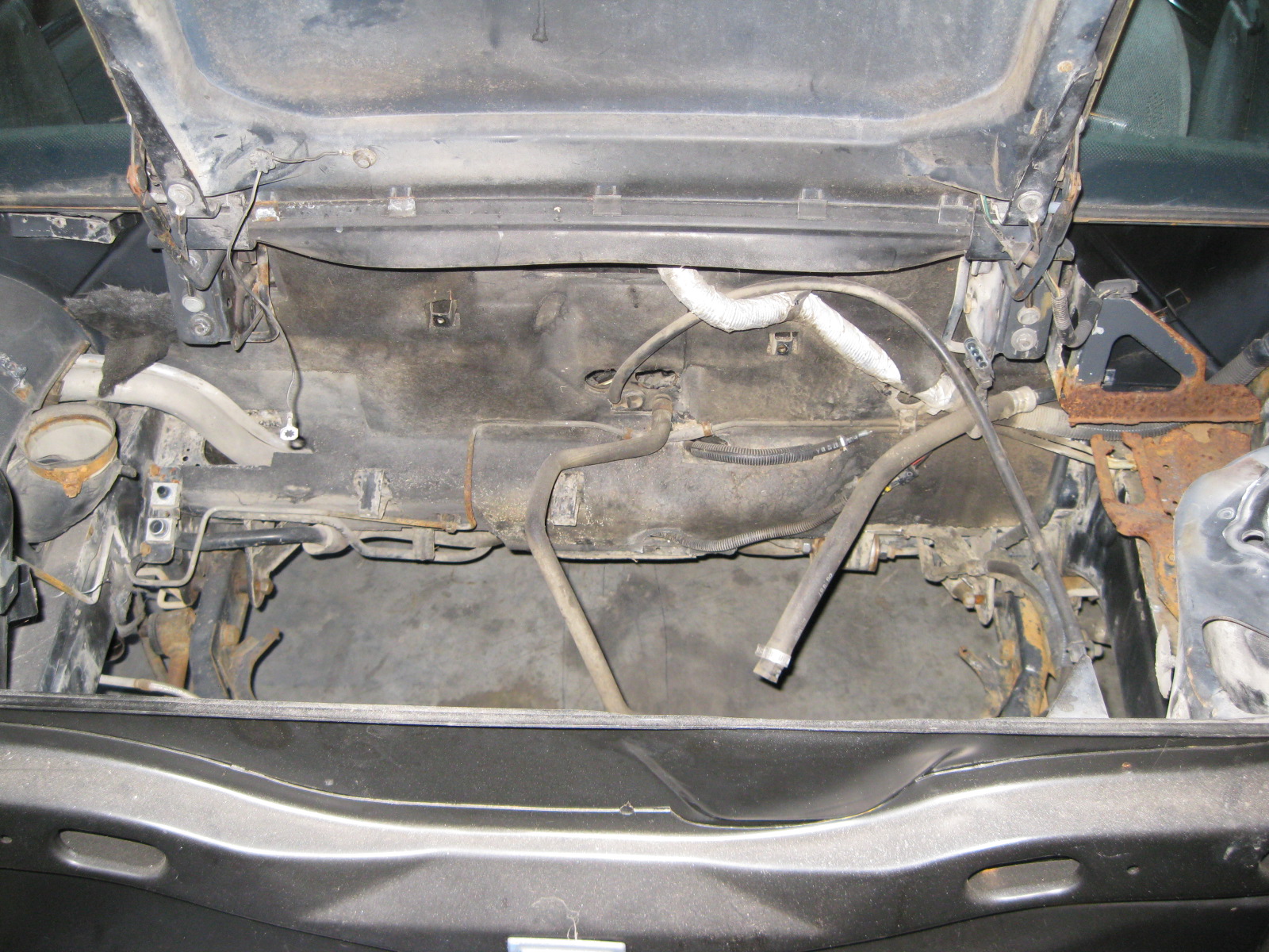
Removed crap:
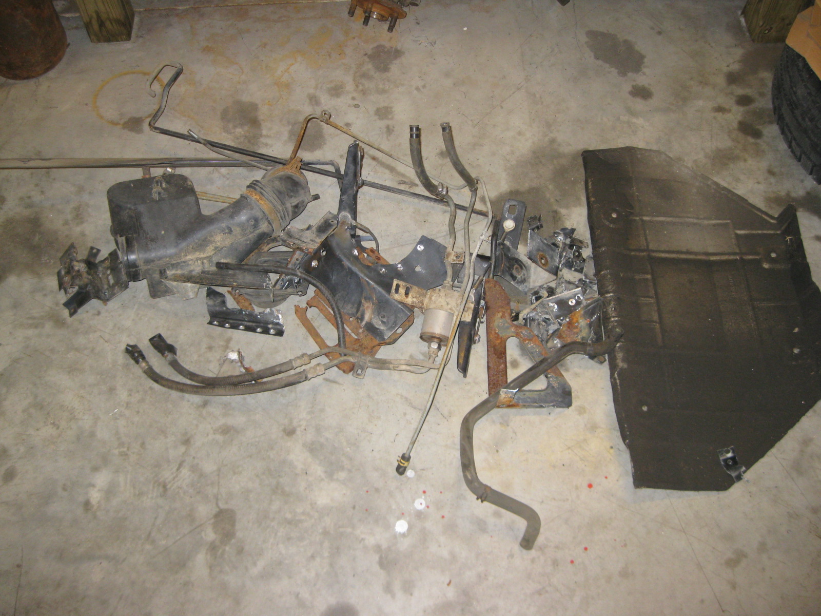
After:
The test fit showed a couple of areas that needed some additional clearance. F40 transmission to the driver side frame rail has about 1/4" clearance to the factory notch in the frame and this is after I ground down the rib on the end of the transmission about 3/16”. Right now the notch isn't centered to the transmission and the tranny is very close to the edge of the notch... it would look better with the notch moved to the rear 1".
Moving the factory notch:
The relocated frame notch is going to workout just fine:
Welded in the relocated panel on the DS frame rail,
Here is the clearance to the decklid hinge box... but the water pump isn't on the engine. These things clutter up an otherwise clean firewall and so instead of cutting them back for clearance, I will just eliminate them entirely.
These hinge boxes clutter up an otherwise clean firewall and so instead of cutting them back for clearance, I will just eliminate them entirely.
Here is an underside view of the factory hinge once the hinge box is removed:
The plan is to cut the hinge off where it bends for the attachment to the stock hinge boxes. Then weld a piece of 1/4" steel to the hinge and have this plate bolted to the fiero chassis... something like this:
Here are the two modified hinges ready to be installed:
Hinges are pretty much done, I may reduce the 1/4" spacer to 1/8" to better line up the body line at the decklid vents:
Creating a new smooth firewall panel:
Here is the template:
Transferred to the sheet sheet:
First test fit of the panel:
I have marked a few places where I can remove a little more material to even up the gaps and provide room for the panel to expand slightly.
Now I decided to start actually working on the Black cars chassis and stop using the blue car for mock up. Here is what the engine bay looked like once the 2.8/Getrag was removed:
Removed crap:
After:
Last edited by fieroguru; 09-30-2012 at 10:33 AM.
09-30-2012, 10:47 AM
#33
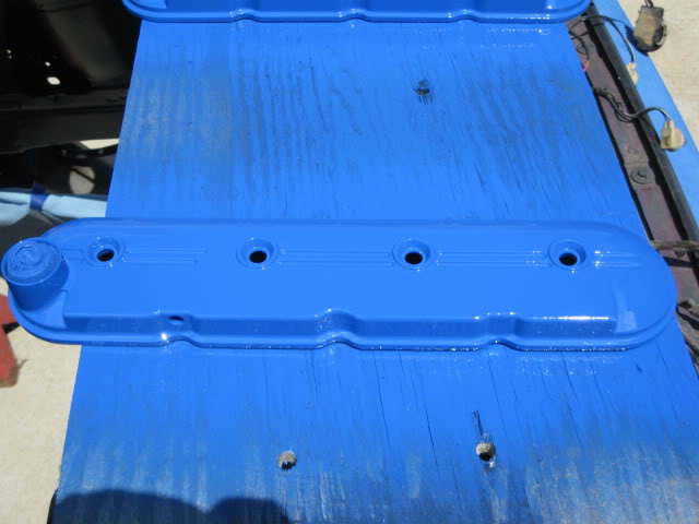
Now that the black fiero's chassis was ready for the engine, it was time to start putting all the painted items back together.
My button head obsession required that I replace the valve cover bolts with stainless button heads. To do this the stock bolts had to be cut to remove the support sleeve.
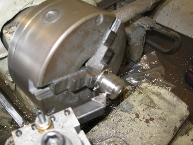
In this pic you can see the small washer on the left that some vendor thought would work fine for these bolts, but it is way too small, and the center hole as too much slop... the larger washer with the smaller hole is the one I modified:
I stacked 10 on a bolt and put them in the lathe and turned them down to the desired size:
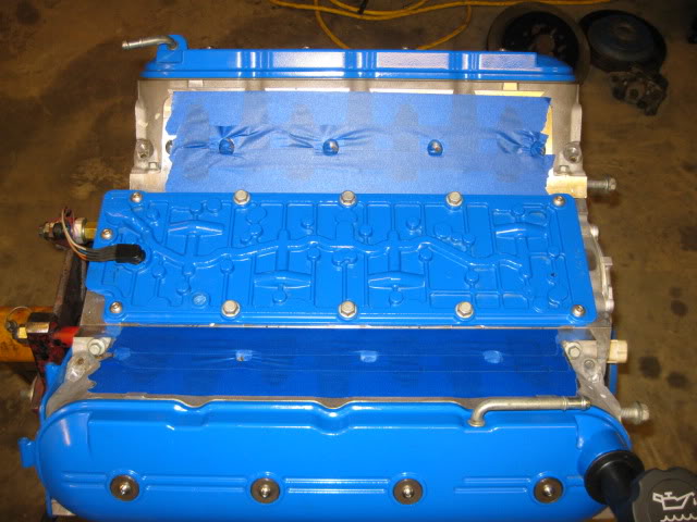
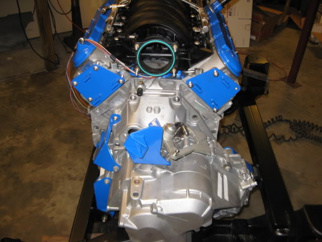
Here is a pic of the engine going back together... I was able to get the valley cover installed, if you look close you will notice I was slacking and only used the button heads on the bolts that will be visible:
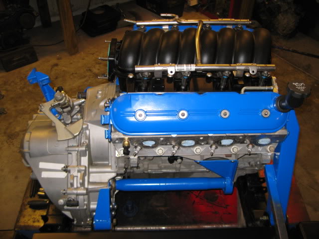
Then the intake went on with more stainless steel button heads:
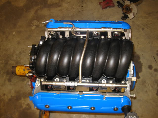
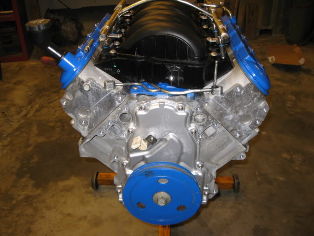
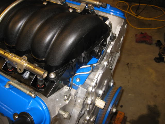
Installed the stainless button heads in the timing cover and installed the balancer for the last time. It is hard to see in this pic, but I also cut the vacuum elbow off the end of the intake and tapped the holes for 2 plugs. The brake booster vacuum supply will come off the neck of the intake.
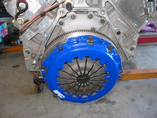
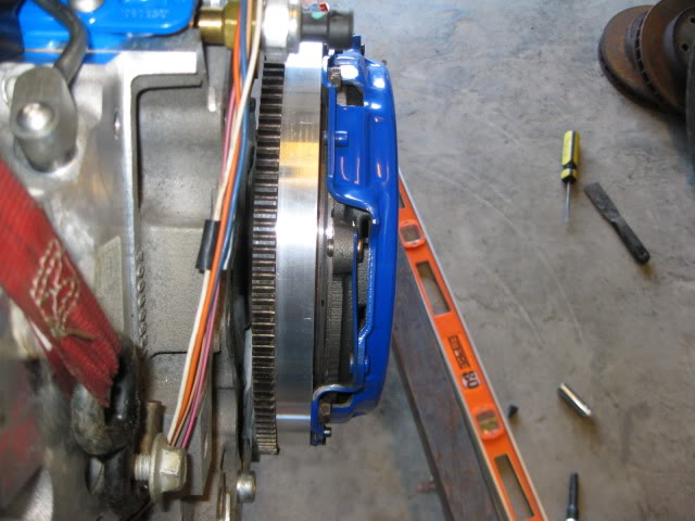
Flywheel installed:
Then I installed the transmission and all the other mounts/brackets that were fabricated for this swap. To support the cradle while all this work is going on, I pulled out my electric/hydraulic scissor lift to keep things are a good working height:
Rear transmission mount:
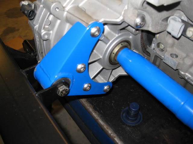
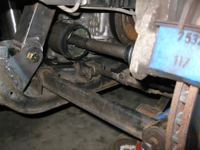
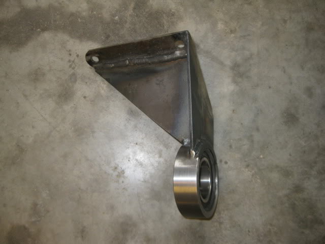
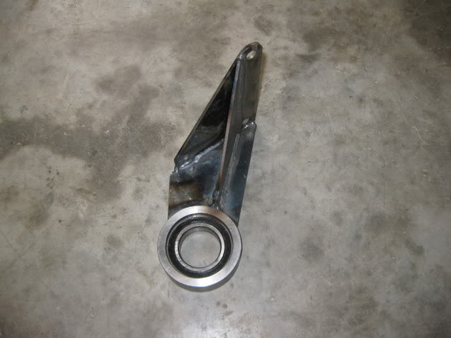
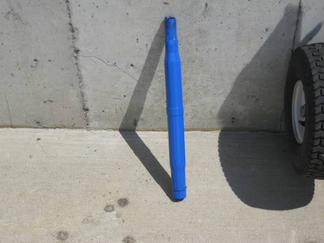
Modified Intermediate shaft (modified Saab unit to make it longer) and fabricated bearing support:
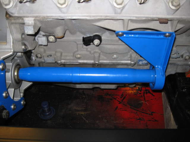
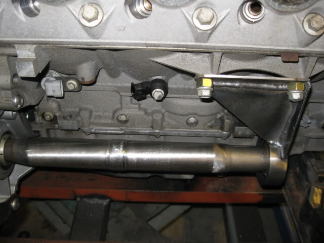
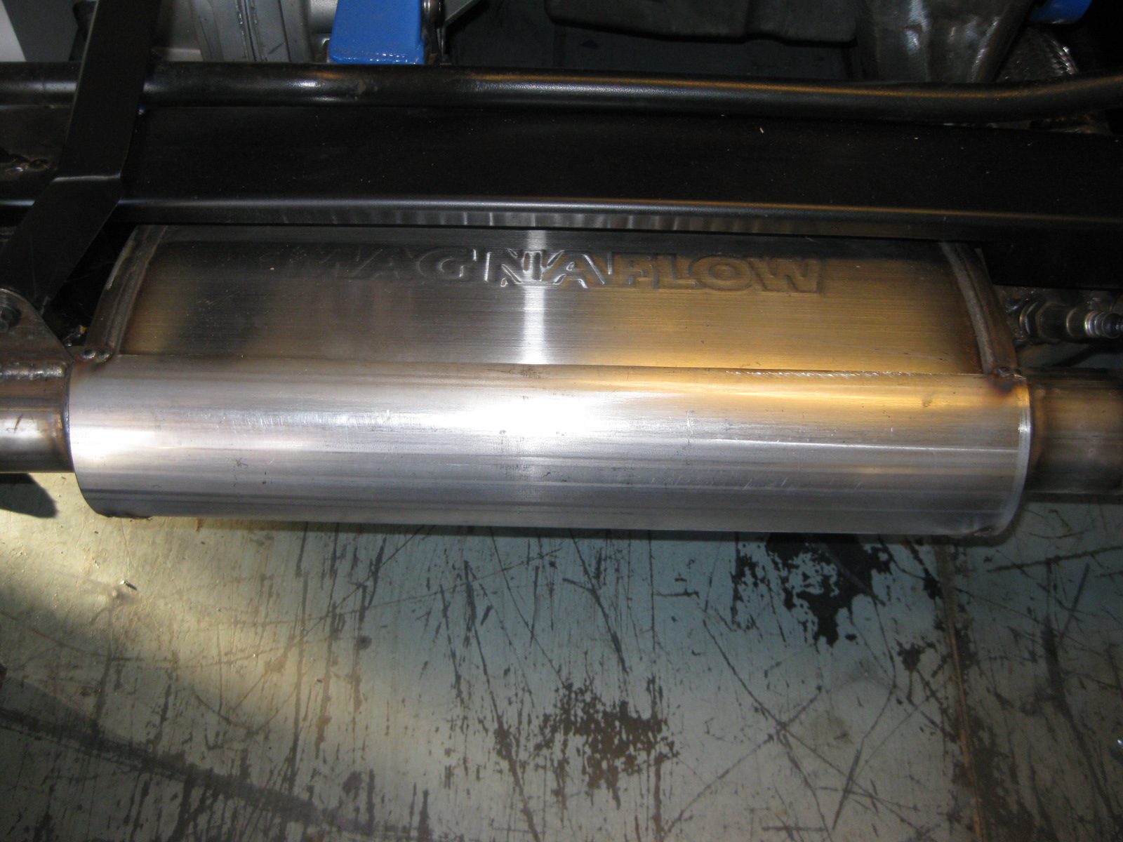
Rear engine mount (the unpainted arm supports the muffler/exhaust):
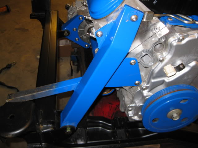
Front engine mount, AC bracket, Alternator bracket and Idler base... yes this is a very busy area:
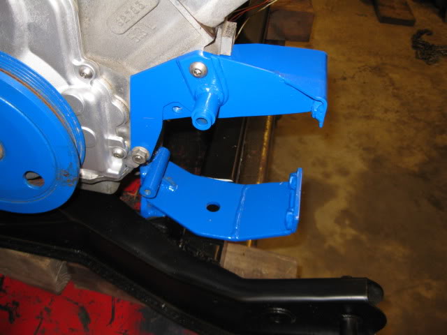
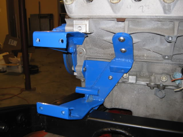
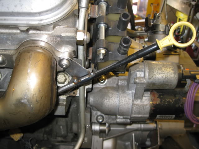
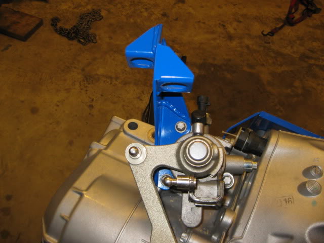
Front transmission mount and starter bracket to use the stock LS4 starter and starter placement:
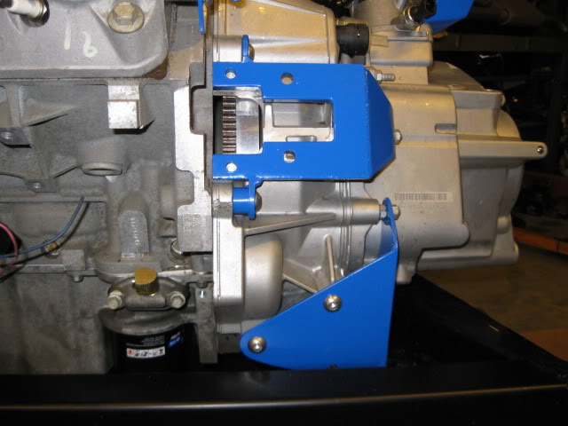
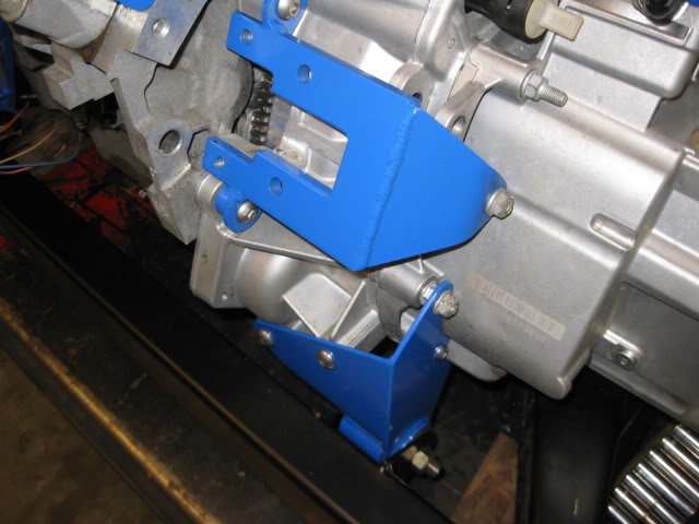
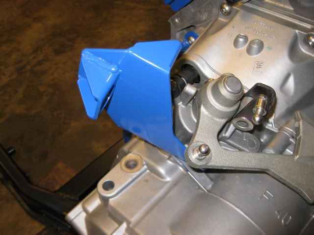
Coil relocation bracket (there is another one on the other head):
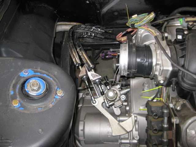
Custom shifter cable bracket for the F40:
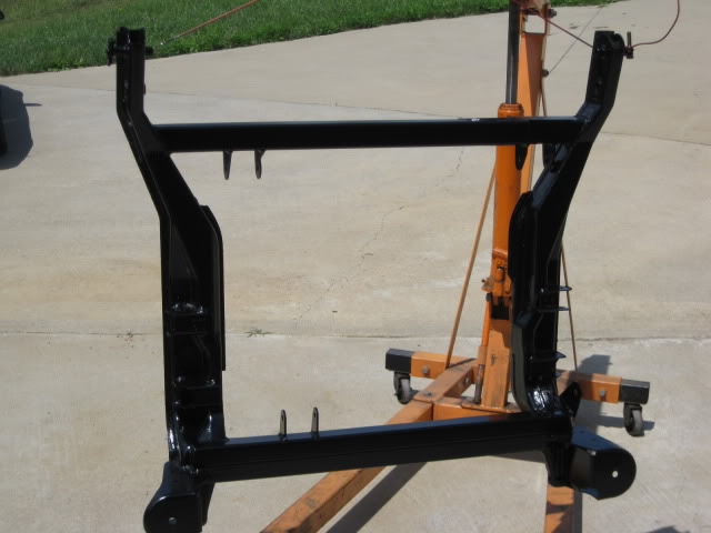
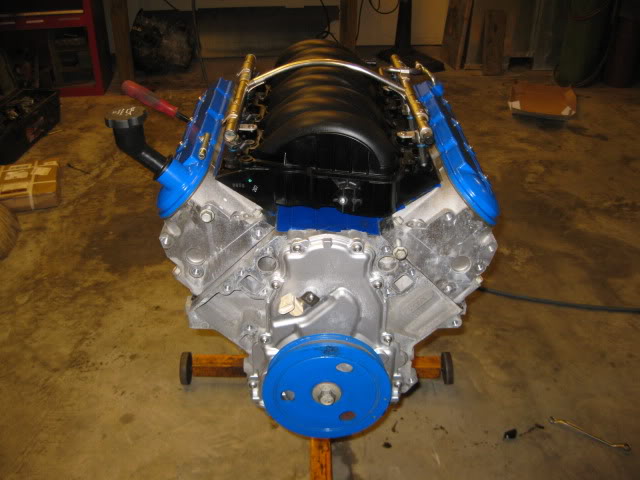
Here are some overall pics:
One of my goals with this swap was to drop the curb weight about 100 lbs vs. the old SBC/Getrag setup. The car with the old setup tipped the scales at 2960 lbs with 1720 on the rear (58.1%). Dropping 100 lbs from the rear would change the rear weight bias to 56.5%.
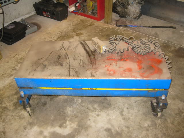
After I finished putting most of the accessories and other parts on, I went ahead and weighed the engine/transmission/cradle on a crude scale setup (2 6x6 beams and 4 bathroom scales - zerod out the weight of the 6x6). Here are a few pics of the setup on the scales:
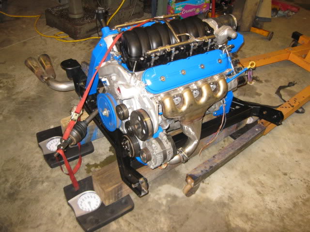
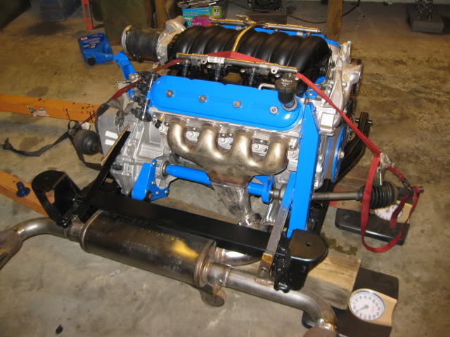
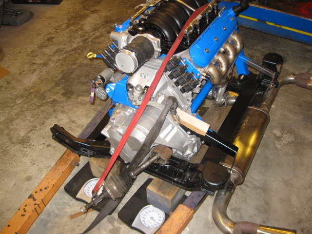
So right now the weights are:
DS PS Total
381 346 727
My button head obsession required that I replace the valve cover bolts with stainless button heads. To do this the stock bolts had to be cut to remove the support sleeve.
In this pic you can see the small washer on the left that some vendor thought would work fine for these bolts, but it is way too small, and the center hole as too much slop... the larger washer with the smaller hole is the one I modified:
I stacked 10 on a bolt and put them in the lathe and turned them down to the desired size:
Here is a pic of the engine going back together... I was able to get the valley cover installed, if you look close you will notice I was slacking and only used the button heads on the bolts that will be visible:
Then the intake went on with more stainless steel button heads:
Installed the stainless button heads in the timing cover and installed the balancer for the last time. It is hard to see in this pic, but I also cut the vacuum elbow off the end of the intake and tapped the holes for 2 plugs. The brake booster vacuum supply will come off the neck of the intake.
Flywheel installed:
Then I installed the transmission and all the other mounts/brackets that were fabricated for this swap. To support the cradle while all this work is going on, I pulled out my electric/hydraulic scissor lift to keep things are a good working height:
Rear transmission mount:
Modified Intermediate shaft (modified Saab unit to make it longer) and fabricated bearing support:
Rear engine mount (the unpainted arm supports the muffler/exhaust):
Front engine mount, AC bracket, Alternator bracket and Idler base... yes this is a very busy area:
Front transmission mount and starter bracket to use the stock LS4 starter and starter placement:
Coil relocation bracket (there is another one on the other head):
Custom shifter cable bracket for the F40:
Here are some overall pics:
One of my goals with this swap was to drop the curb weight about 100 lbs vs. the old SBC/Getrag setup. The car with the old setup tipped the scales at 2960 lbs with 1720 on the rear (58.1%). Dropping 100 lbs from the rear would change the rear weight bias to 56.5%.
After I finished putting most of the accessories and other parts on, I went ahead and weighed the engine/transmission/cradle on a crude scale setup (2 6x6 beams and 4 bathroom scales - zerod out the weight of the 6x6). Here are a few pics of the setup on the scales:
So right now the weights are:
DS PS Total
381 346 727
09-30-2012, 11:10 AM
#34
About this time I had an unexpected move. The house we had been leasing for 2.5 years was being sold to a family member of the landlord. We had 3 months to packup and find another place.
Instead of going through this mess again, we decided to just buy a house. So with the move, I put everything together to make the black car a roller:
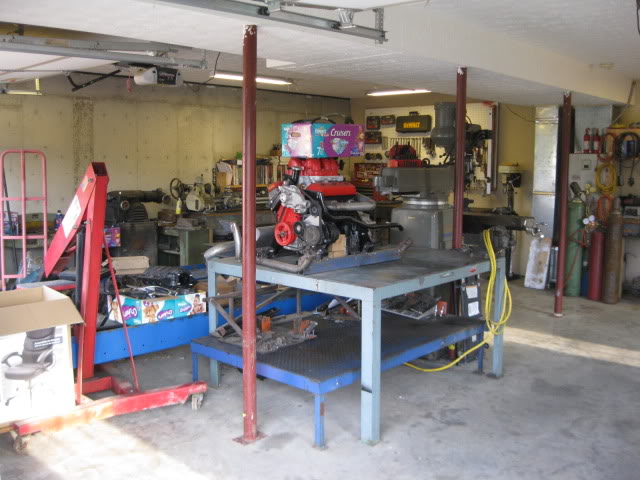
Bye-Bye old garage:
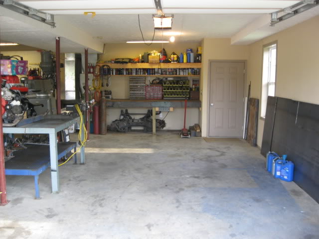
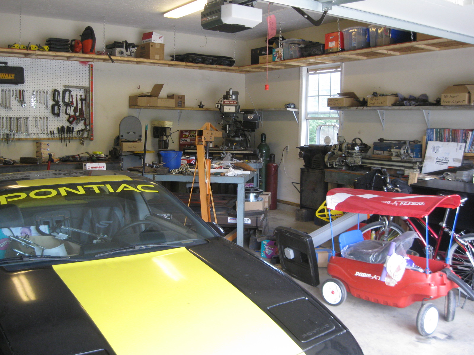
As we were house hunting, the wife focused on the house, I focused on the garage. I had to make sure that all my tools and atleast 1 fiero would fit in the garage with some room to work.
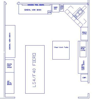
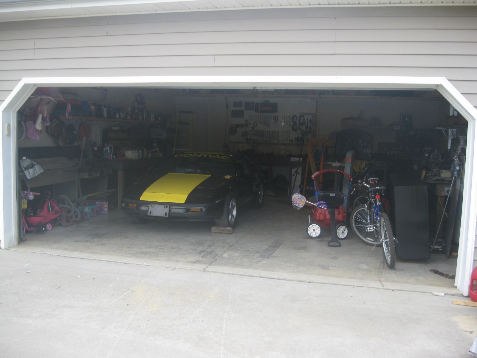
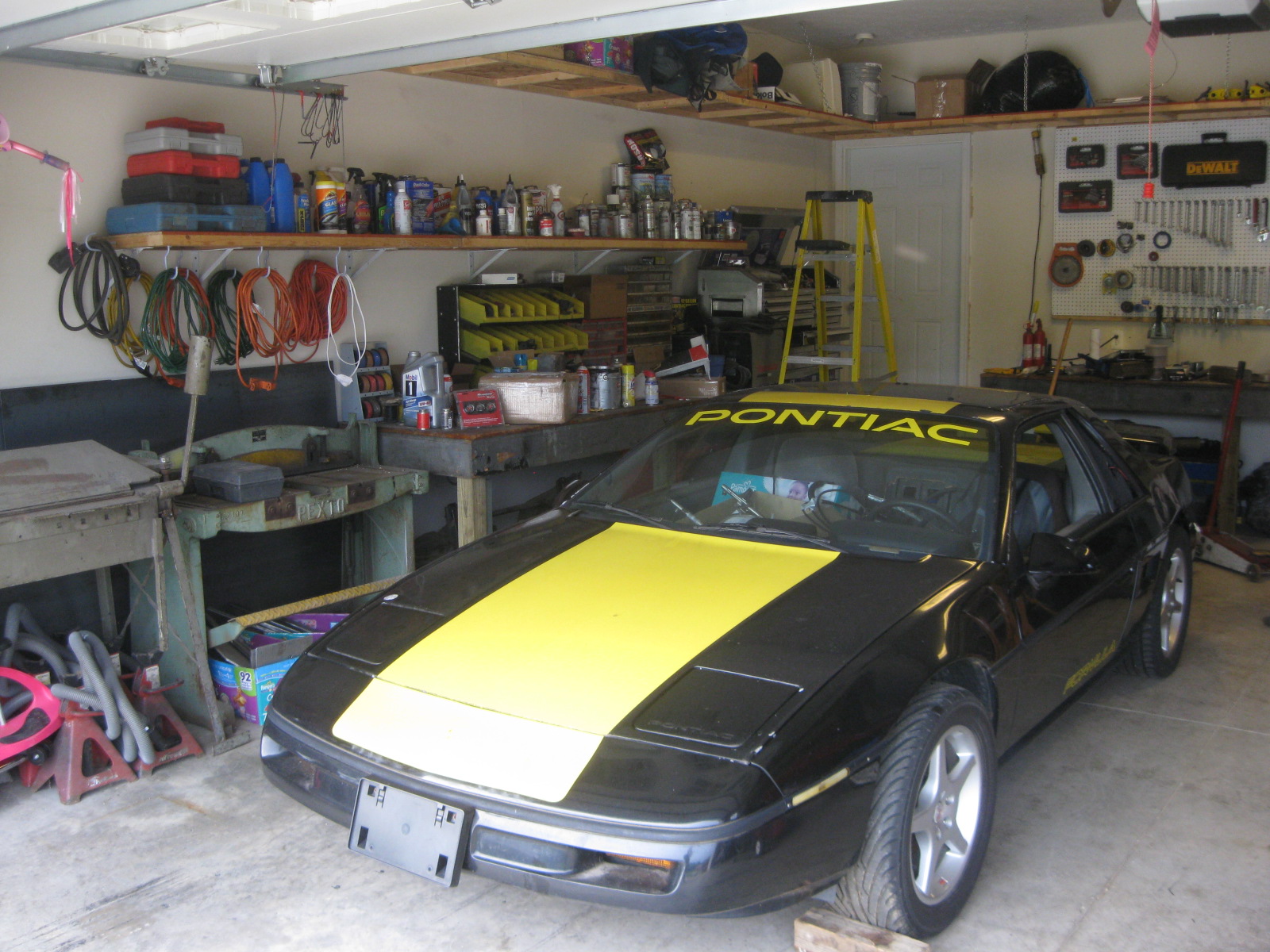
Here is the new garage:
After a couple of months dealing with new house issues, it was time to pull the drivetrain once more and start working on the details of the swap.
Instead of going through this mess again, we decided to just buy a house. So with the move, I put everything together to make the black car a roller:
Bye-Bye old garage:
As we were house hunting, the wife focused on the house, I focused on the garage. I had to make sure that all my tools and atleast 1 fiero would fit in the garage with some room to work.
Here is the new garage:
After a couple of months dealing with new house issues, it was time to pull the drivetrain once more and start working on the details of the swap.
09-30-2012, 11:50 AM
#35
I really have a thing about engine harness wires... I think they look like crap and I want to see as little of them as possible. That means I have to build my harnesses and reroute everything and try to hide as much of it as possible.
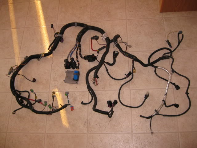
So I started with the stock LS4 harness:
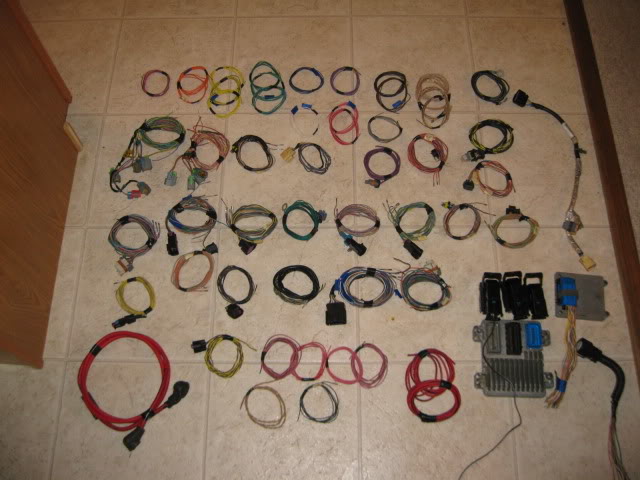
And did this to it:
The coil harness went from this:
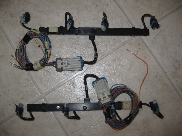
To this:
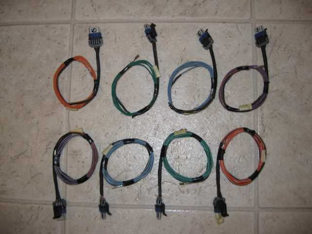
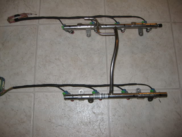
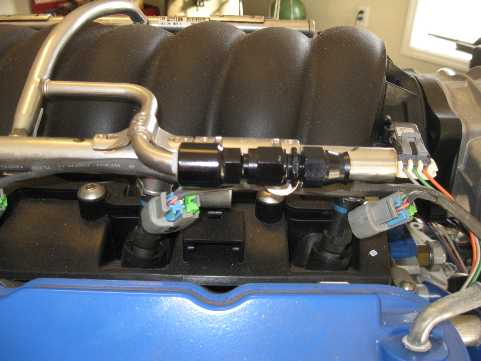
Then I started with the injector portion of the harness and tried to minimze it as much as possible and ran it behind the fuel rail (so the rail will help hide it when viewed in a fiero):
As I started to build the rest of the harness, I started at the furthest point from the ECM (cam sensor) and started building it circuit by circuit and sleeving/looming it as I went:
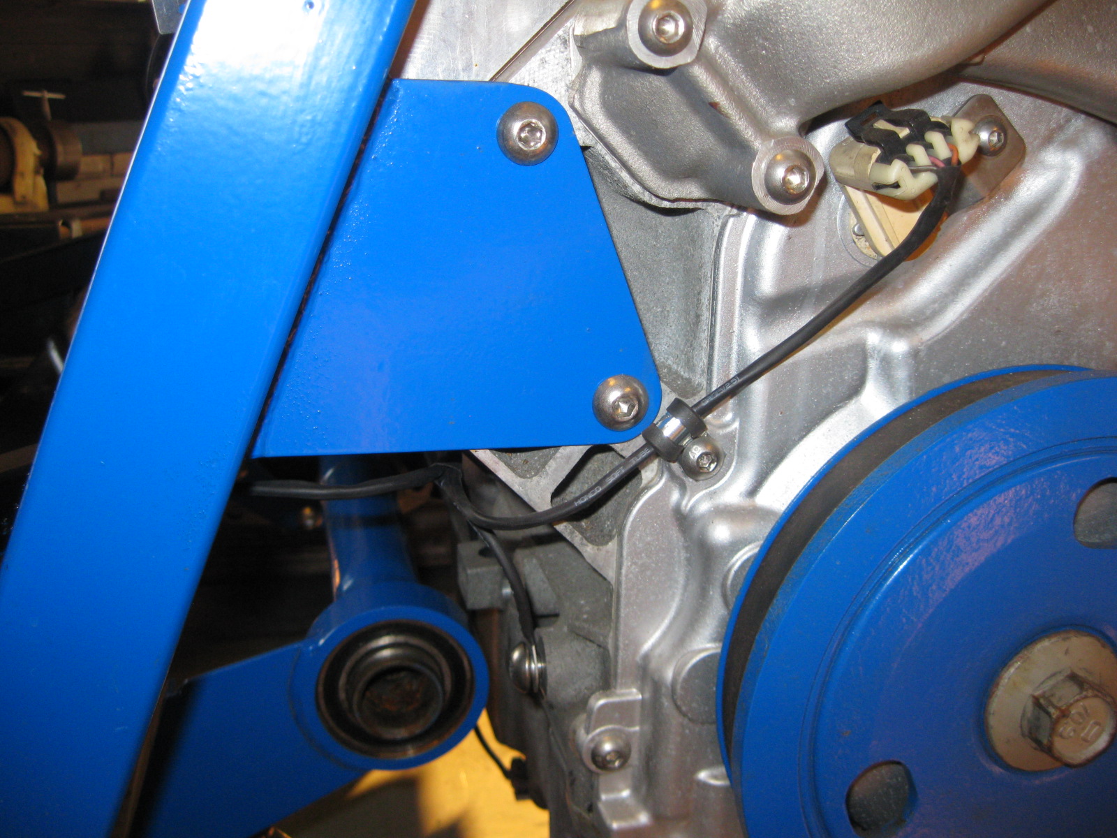
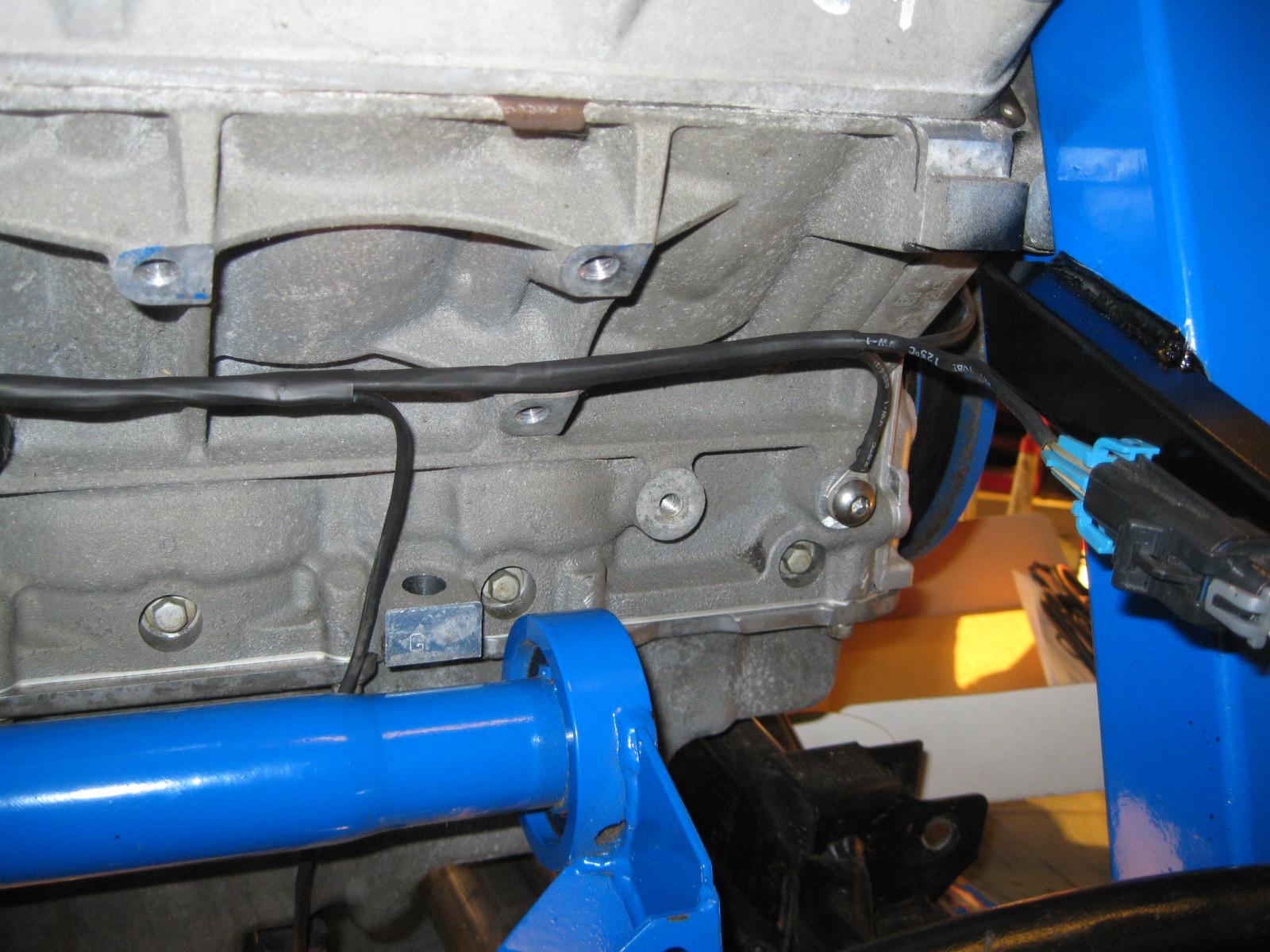
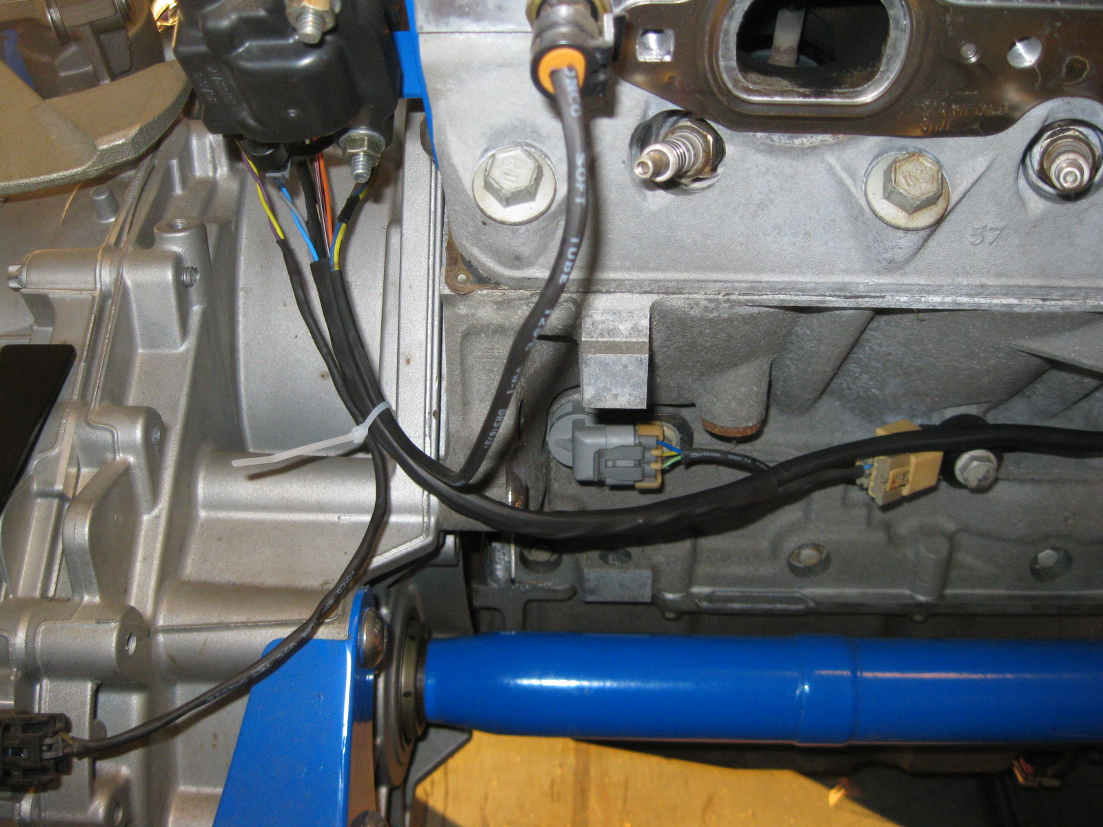
In the picture above, everything under the manifold will be hidden, but the portion as it wraps to the rear of the block will be visible and there isn't much I can do about it especially since the temp sender and the VSS wires have to joint it.
I relocated the coolant temp sender to the #8 cylinder as this end of the block is the hottest (in the event I run NOS or boost). I also switched to the 3 wire 1997 temp sender with an analog output for the dash temp gauge.
Then the harness continued and picked up the front back of coils. The coils each have their individual connector with a short length of wire, so the main harness can be tucked up alongside the engine block and be hidden by the coils, and throttle body. The rear injector harness also joins the main harness between the rear coils and TB:
The harness is still a work in progress...
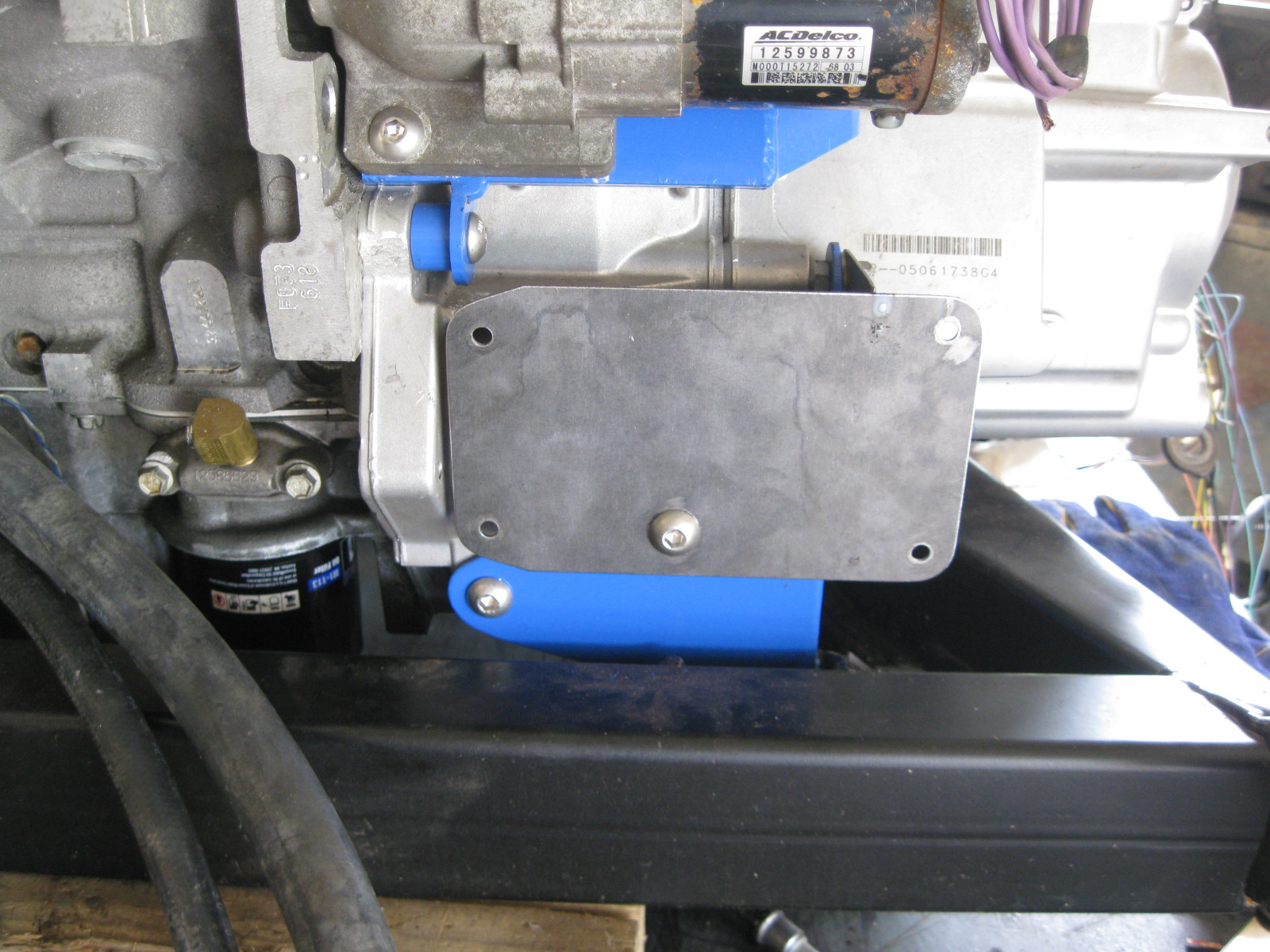
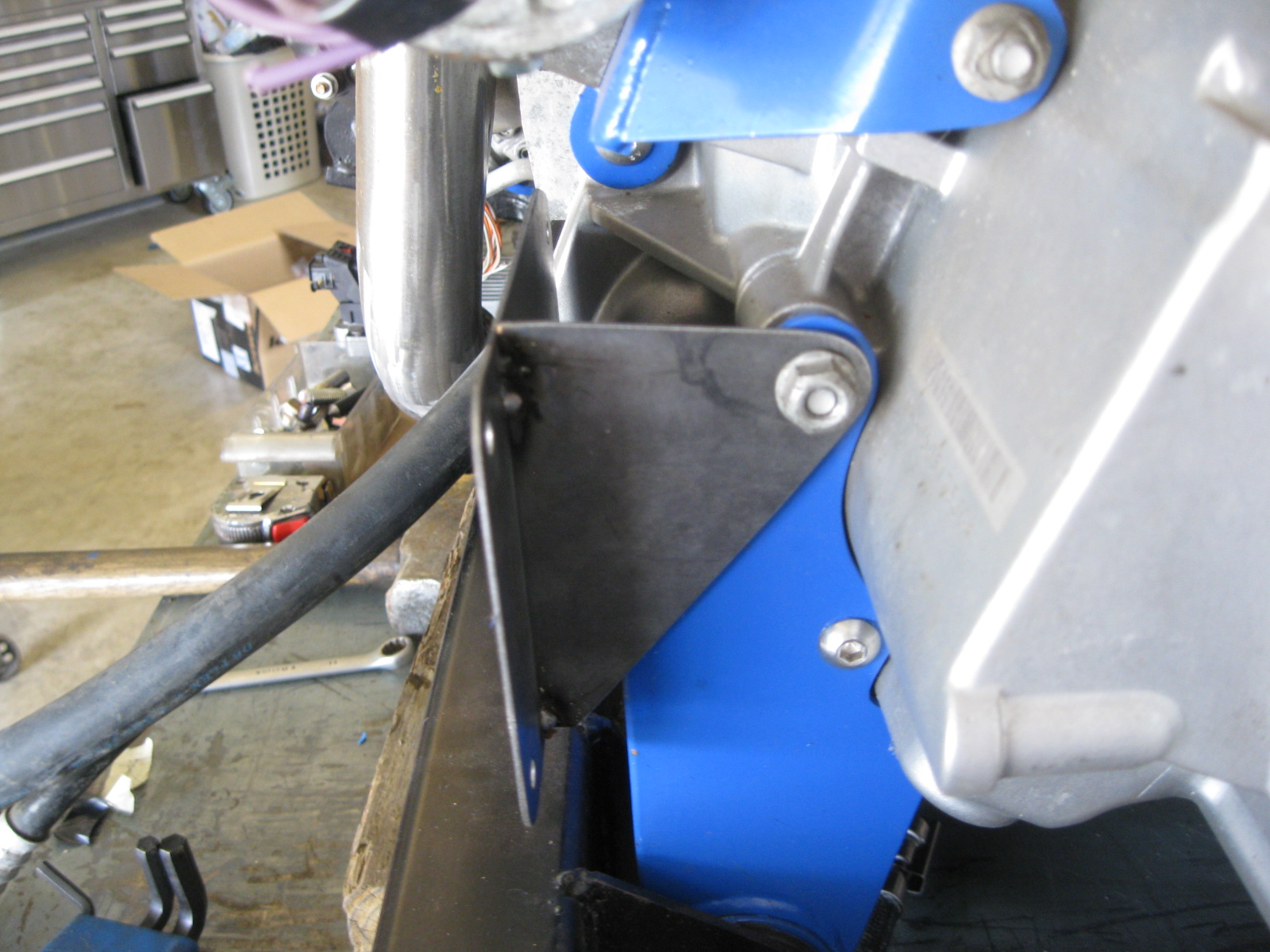
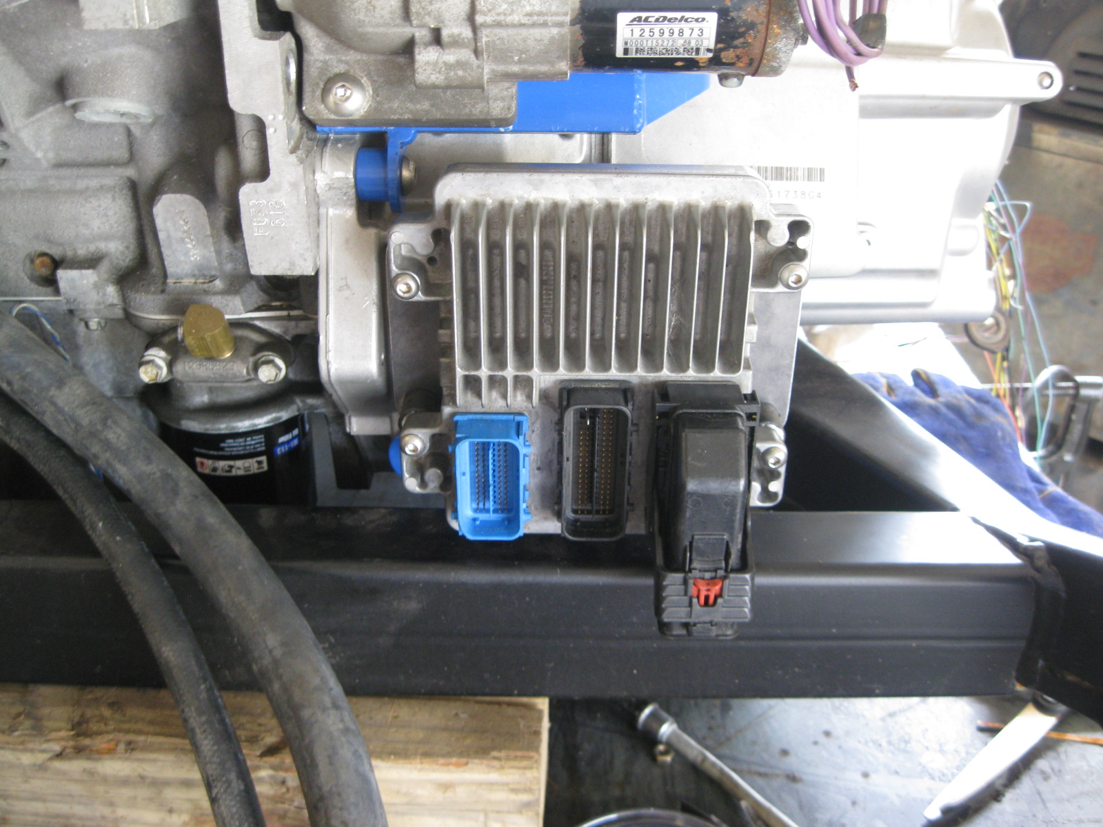
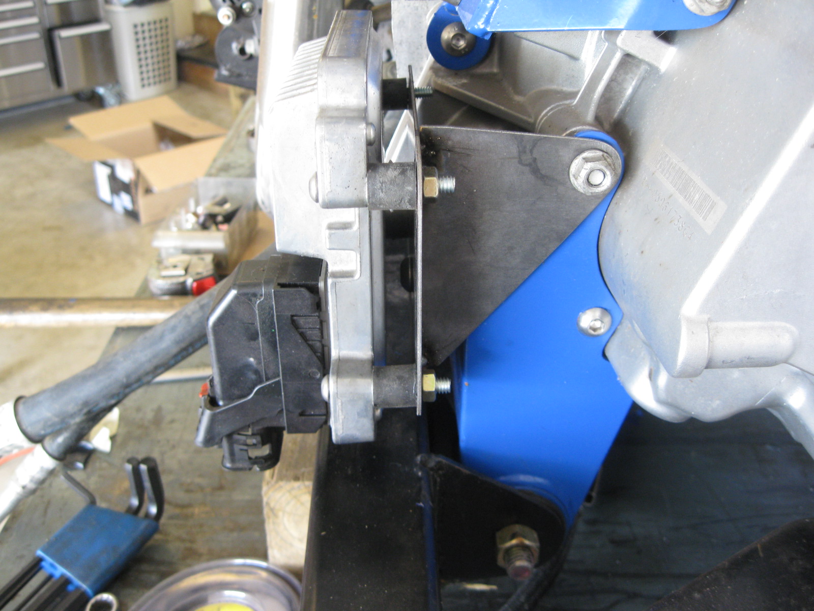
I wanted to mount the ECM on the drivetrain to reduce the # of wires that have to go into the passenger compartment, and to keep it out of sight. Here is the mounting location and the bracket for it.
So I started with the stock LS4 harness:
And did this to it:
The coil harness went from this:
To this:
Then I started with the injector portion of the harness and tried to minimze it as much as possible and ran it behind the fuel rail (so the rail will help hide it when viewed in a fiero):
As I started to build the rest of the harness, I started at the furthest point from the ECM (cam sensor) and started building it circuit by circuit and sleeving/looming it as I went:
In the picture above, everything under the manifold will be hidden, but the portion as it wraps to the rear of the block will be visible and there isn't much I can do about it especially since the temp sender and the VSS wires have to joint it.
I relocated the coolant temp sender to the #8 cylinder as this end of the block is the hottest (in the event I run NOS or boost). I also switched to the 3 wire 1997 temp sender with an analog output for the dash temp gauge.
Then the harness continued and picked up the front back of coils. The coils each have their individual connector with a short length of wire, so the main harness can be tucked up alongside the engine block and be hidden by the coils, and throttle body. The rear injector harness also joins the main harness between the rear coils and TB:
The harness is still a work in progress...
I wanted to mount the ECM on the drivetrain to reduce the # of wires that have to go into the passenger compartment, and to keep it out of sight. Here is the mounting location and the bracket for it.
09-30-2012, 11:57 AM
#36
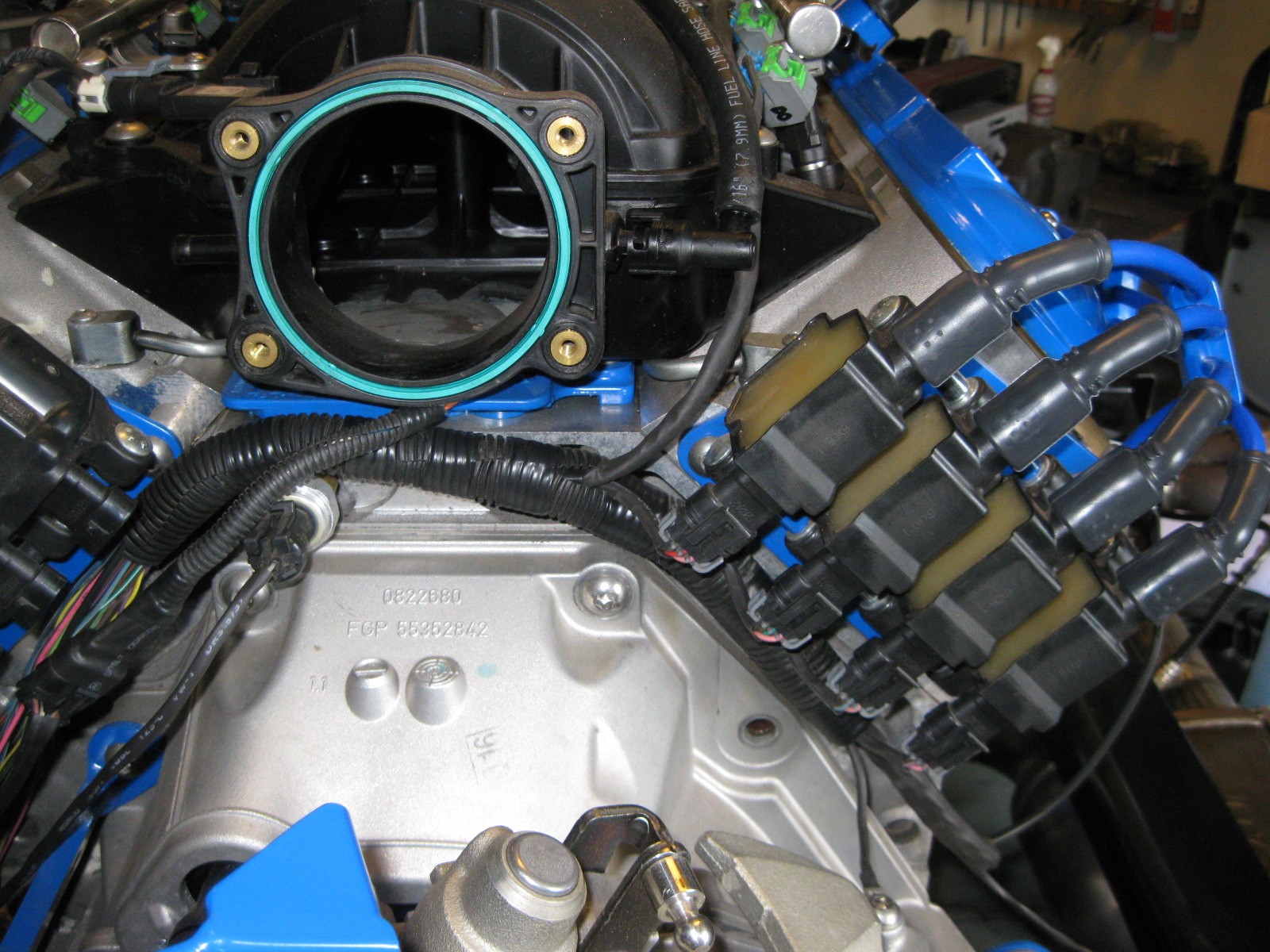
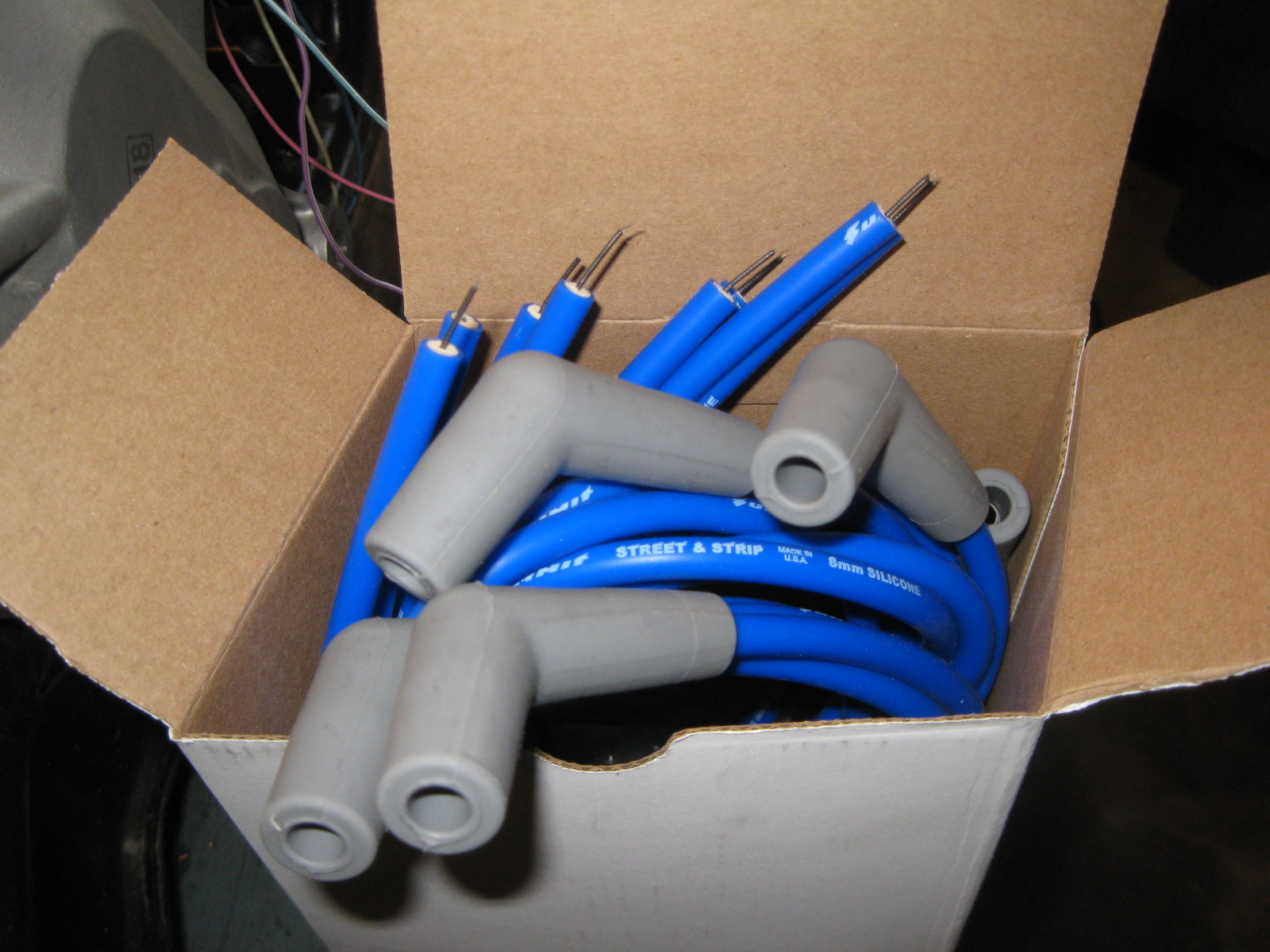
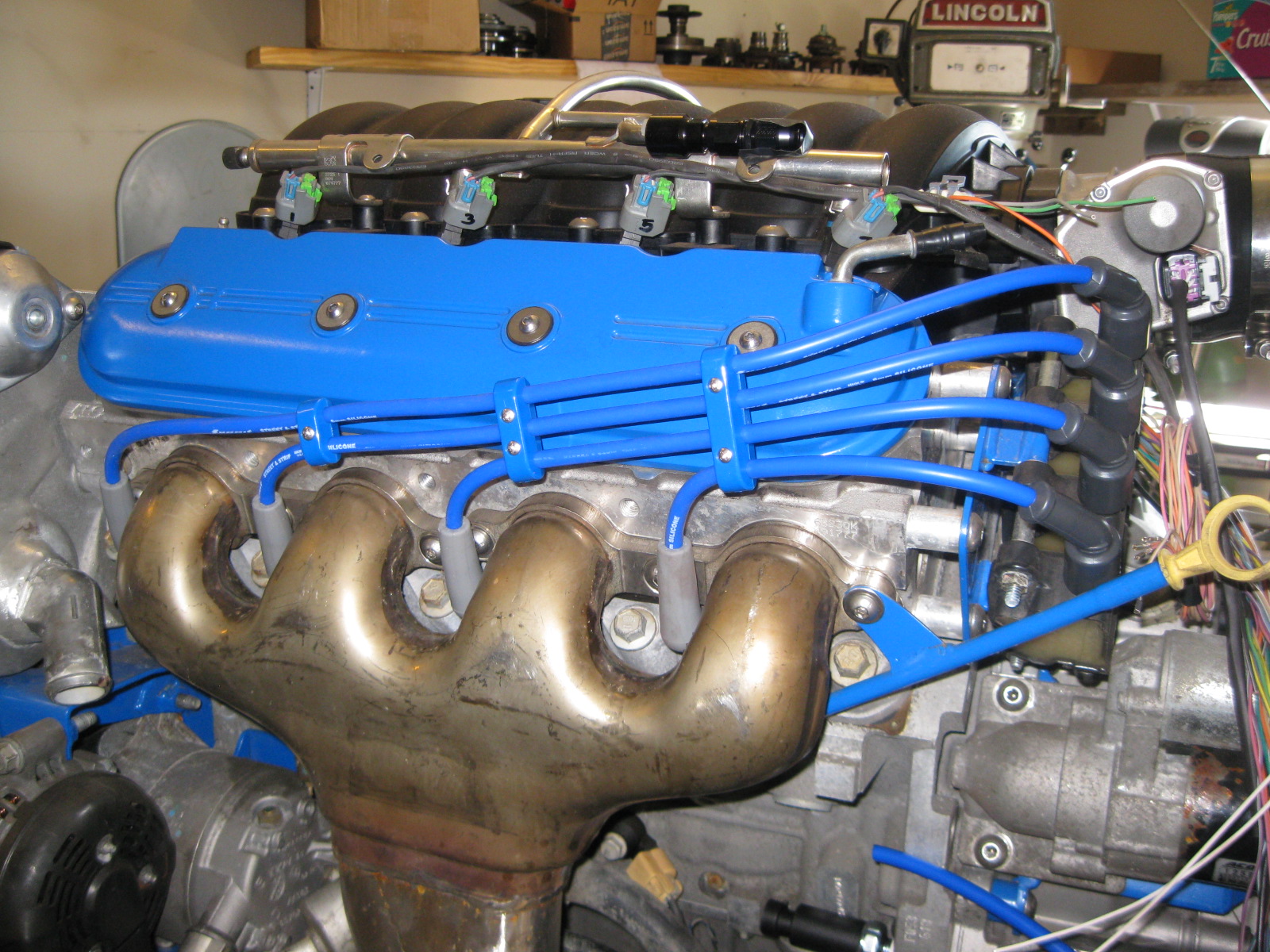
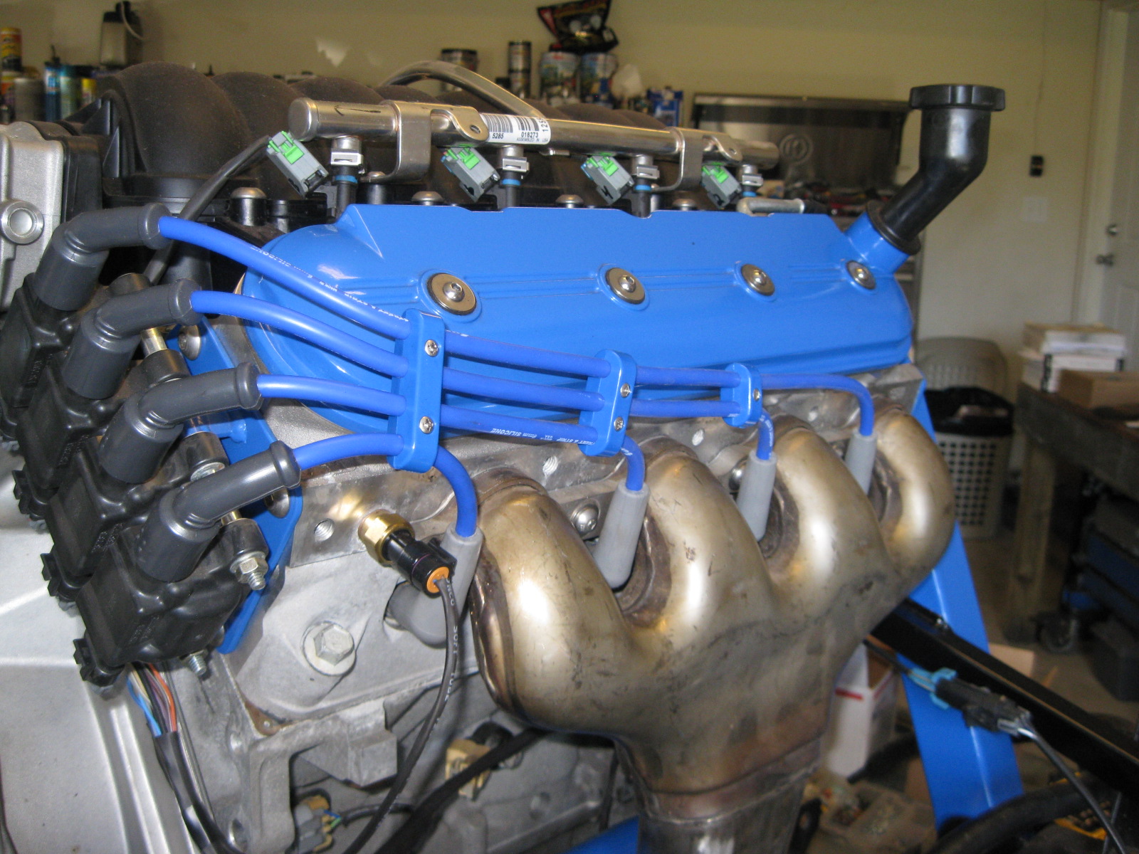
Here are some more pictures of the coil relocation and building the wires. I used the MSD coil boots and some 8mm cut to fit wires from summit with 45 degree spark boots. The boots make the plug wires nearly vertical coming off the plugs, but they are touching the header flange slightly.
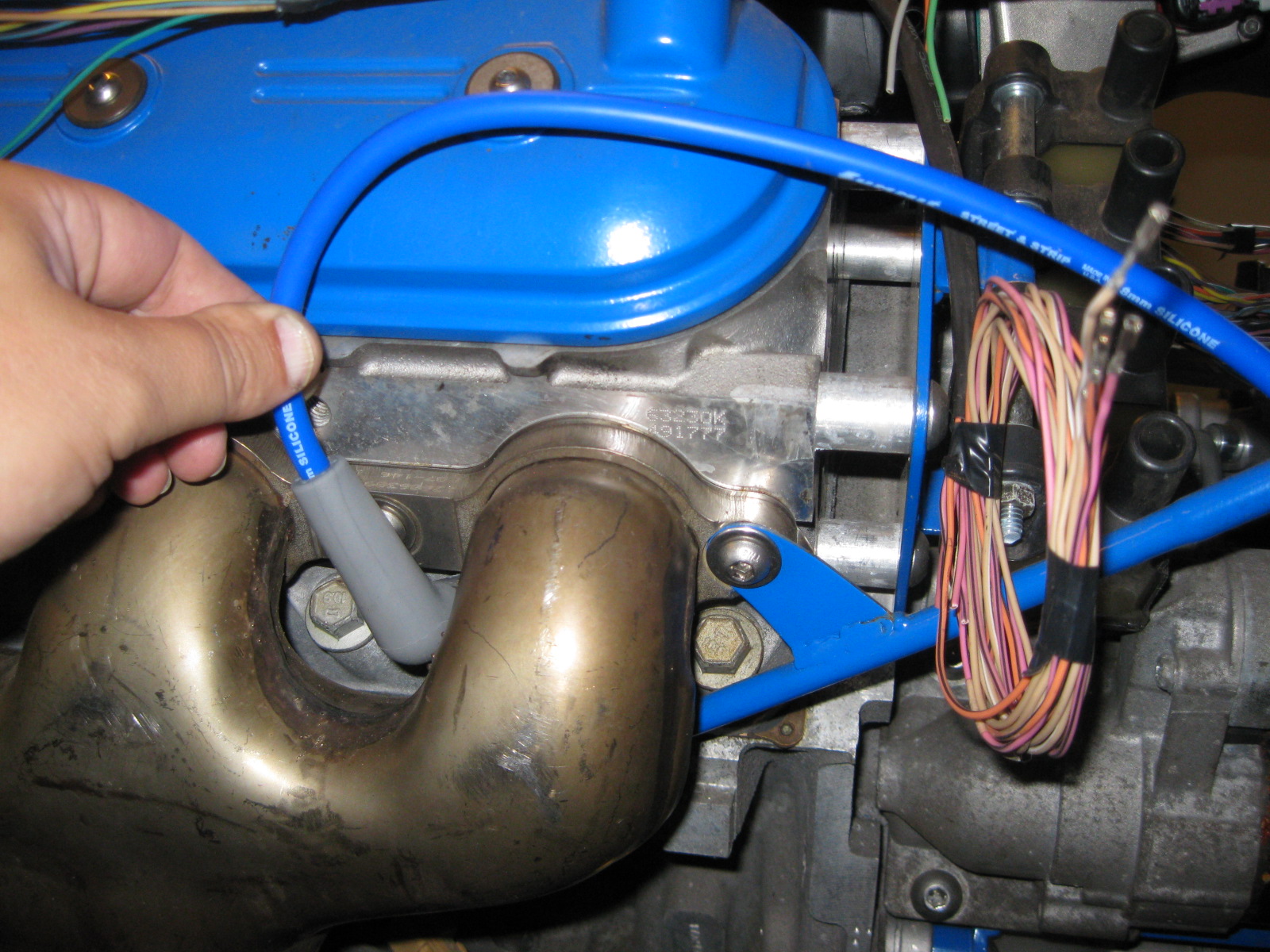
Then it was a matter of choosing the right routing of the wires. I mocked up the front and rear slightly different and decided on the front method:
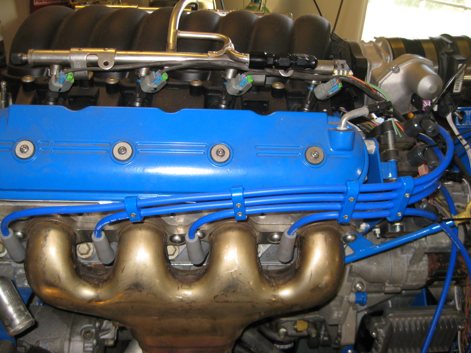
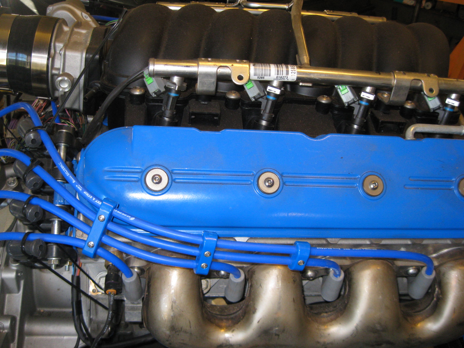
Then I measured and placed the separators equally spaced between each other as well as the same length of wire to plug from each and started trimming the coil end and placing it in the coil to get the plug wires the proper length. Once that was done, I installed the coil ends:
Then it was a matter of choosing the right routing of the wires. I mocked up the front and rear slightly different and decided on the front method:
Then I measured and placed the separators equally spaced between each other as well as the same length of wire to plug from each and started trimming the coil end and placing it in the coil to get the plug wires the proper length. Once that was done, I installed the coil ends:
09-30-2012, 12:06 PM
#37
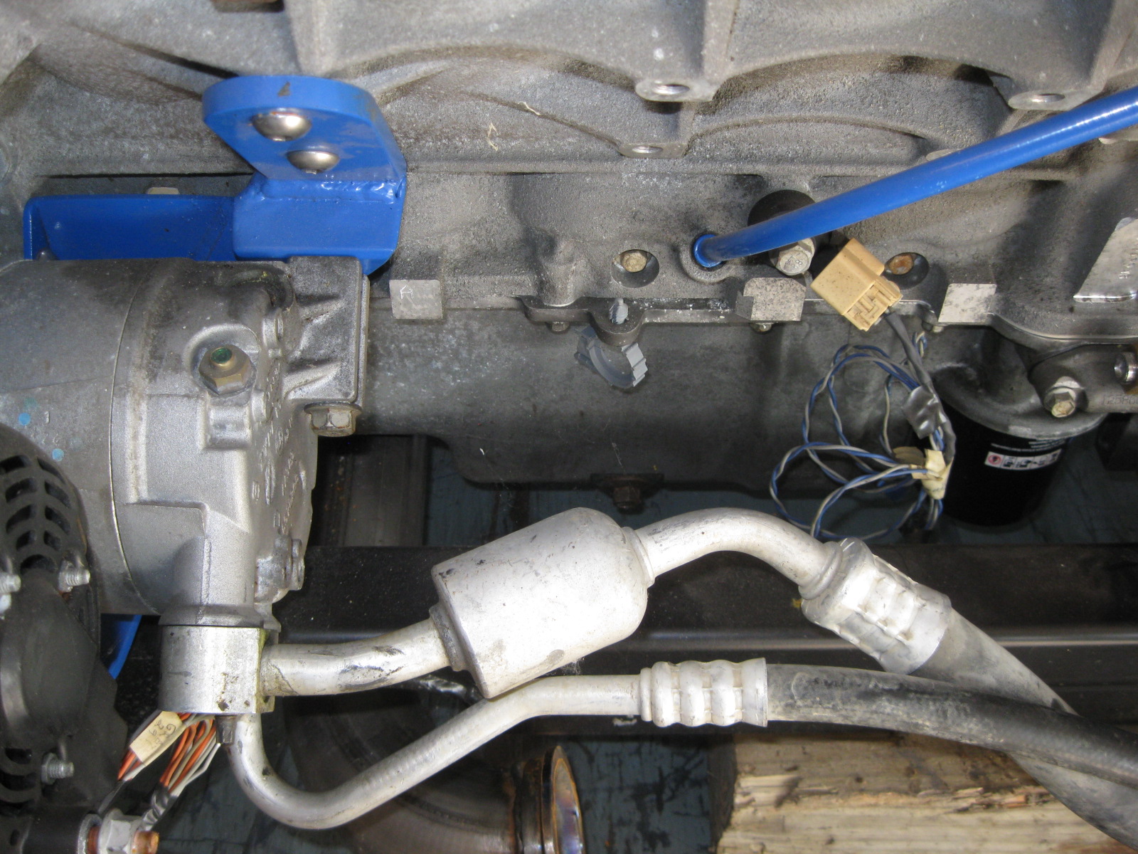
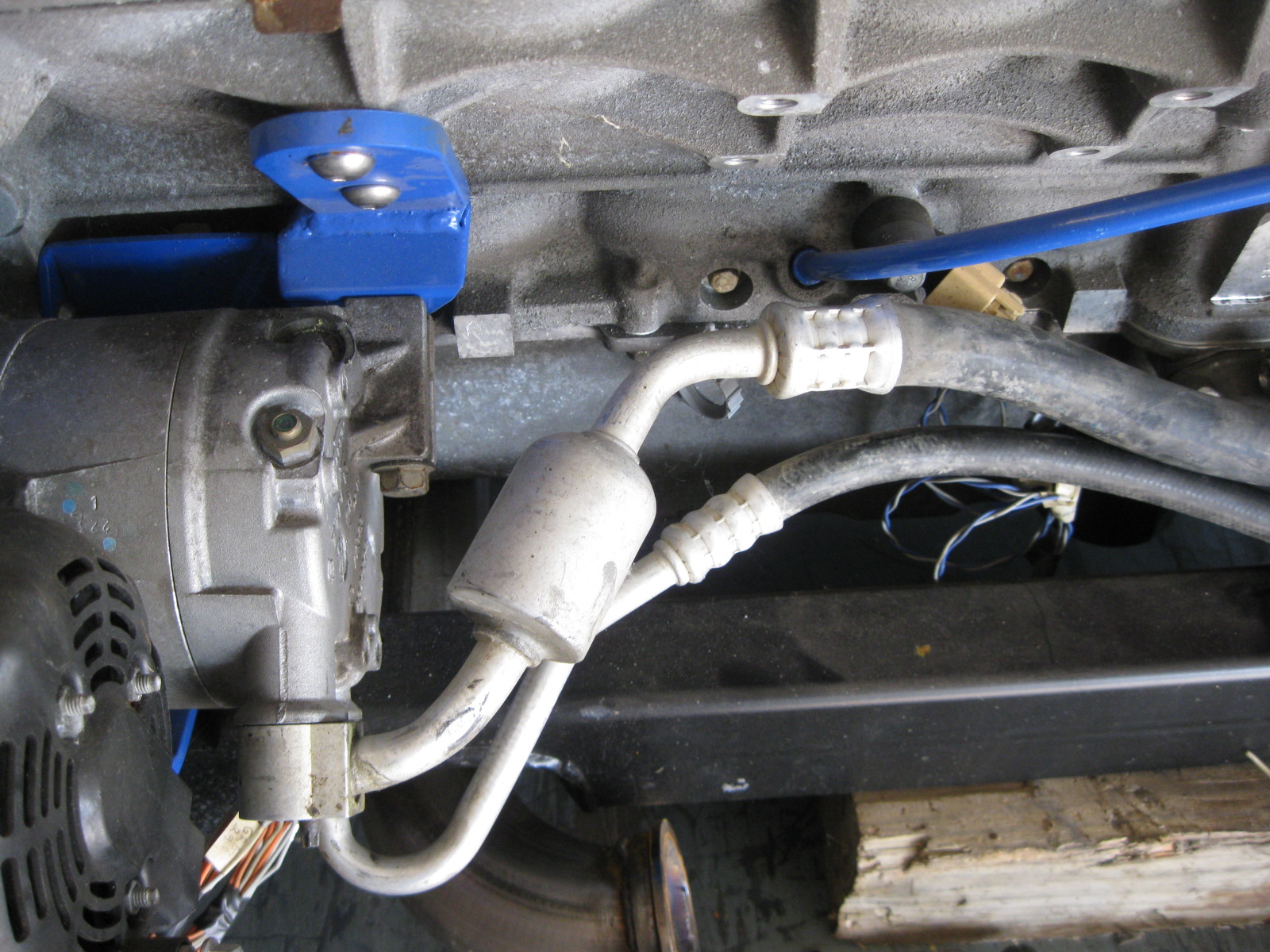
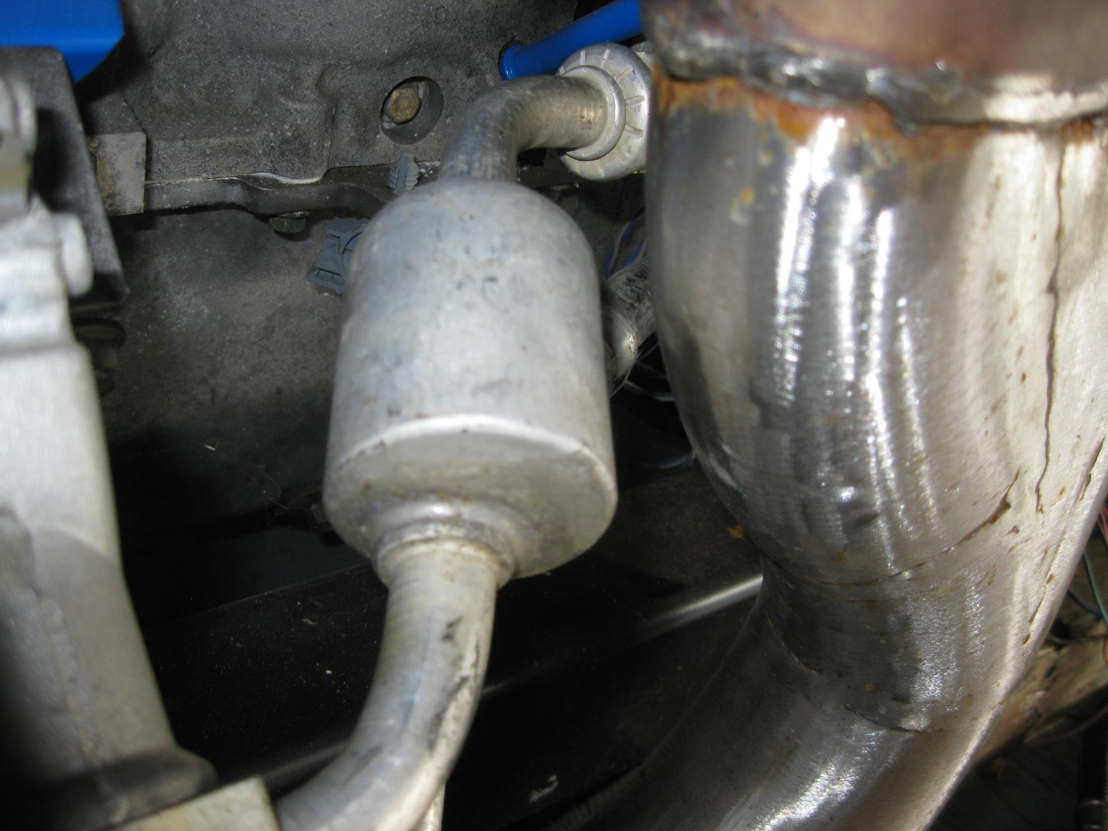
The LS4 AC line would not clear the LS7 exhaust manifold, so I had to tweak it slightly.
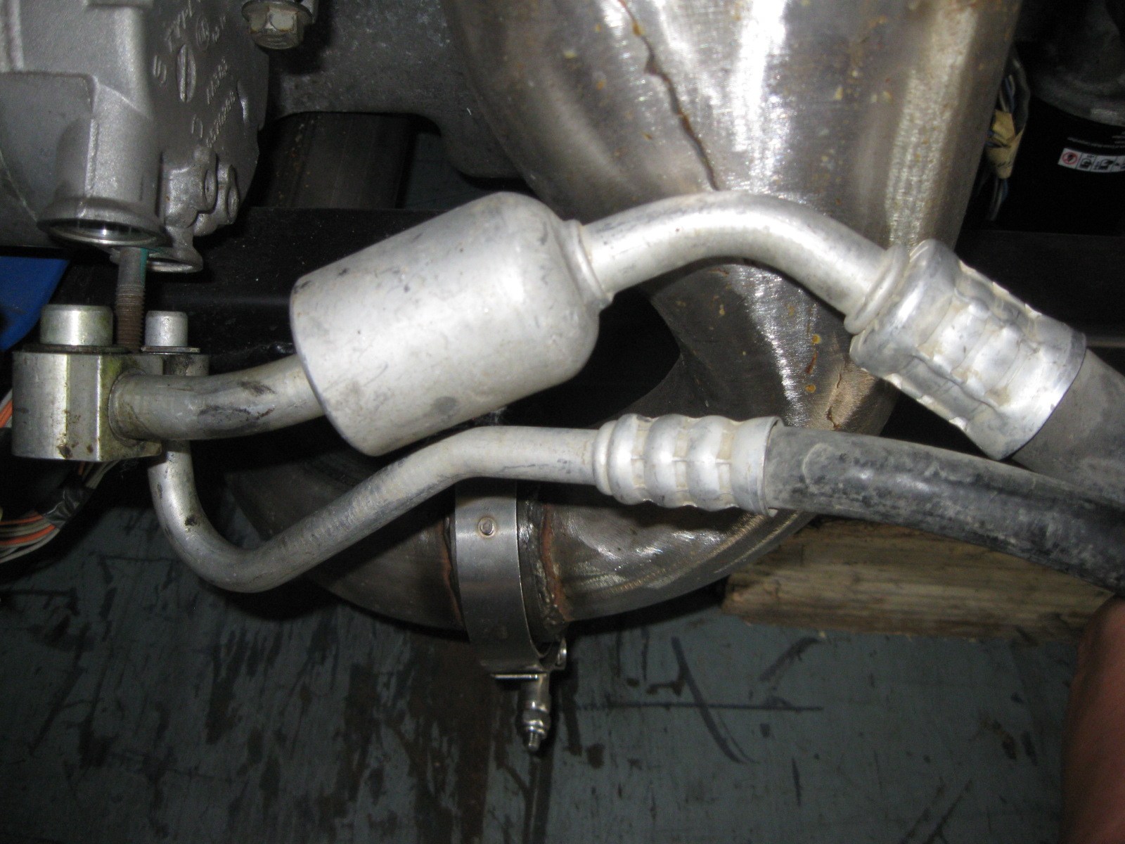
I decided to route the hoses behind the manifold. Here is the stock position:
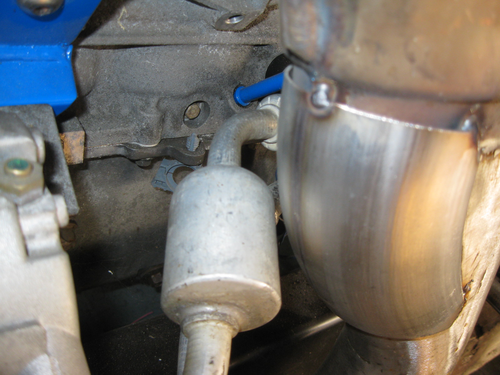
Here is is after being bent:
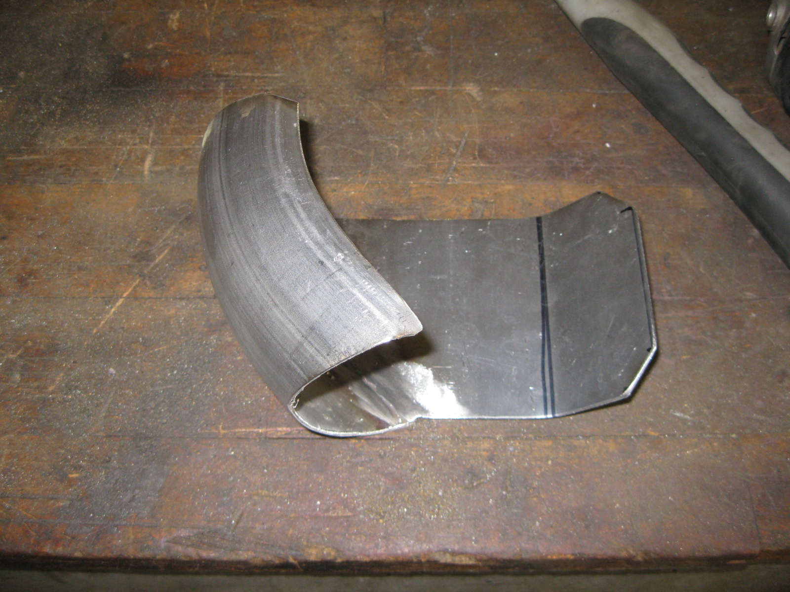
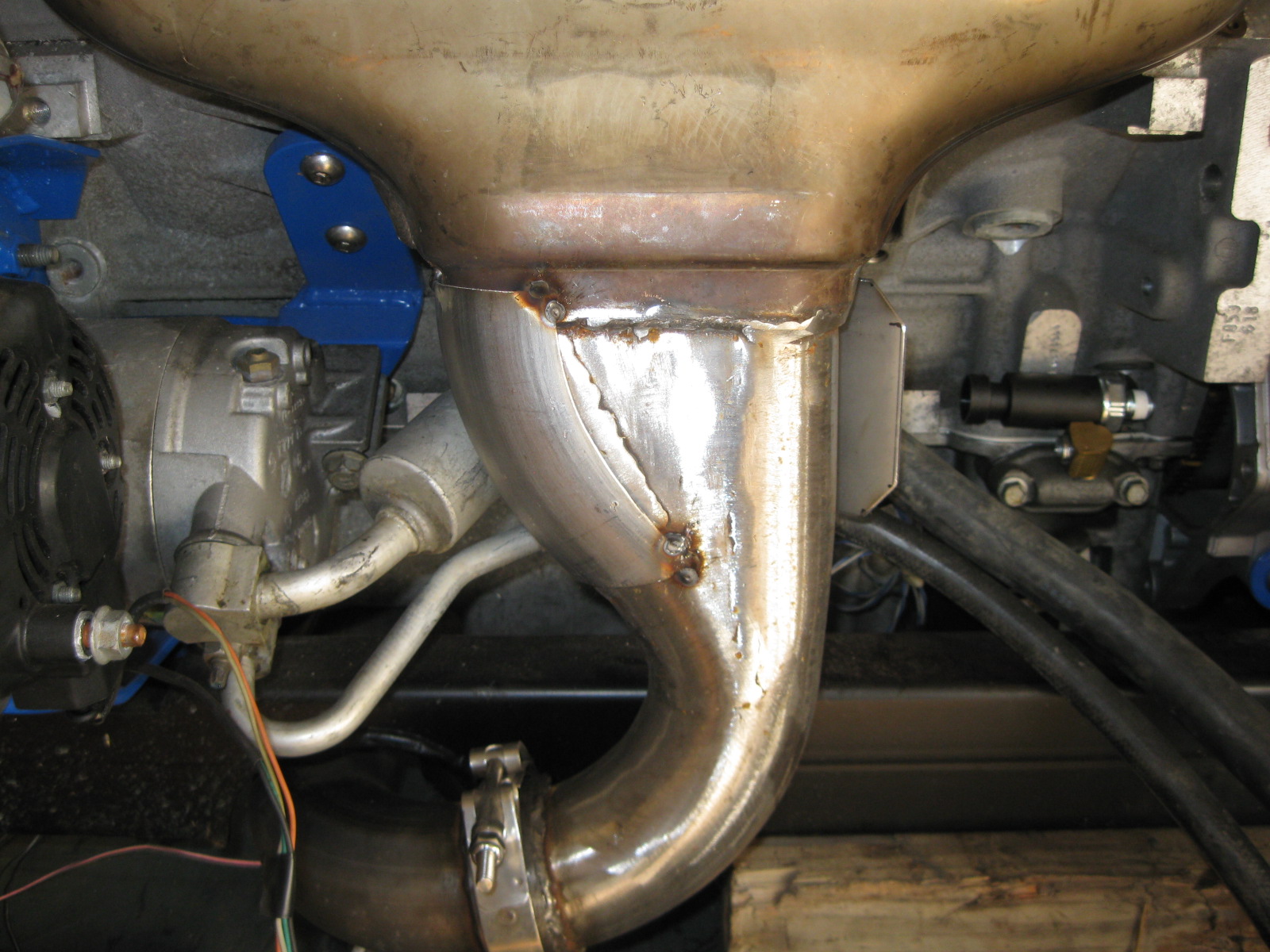
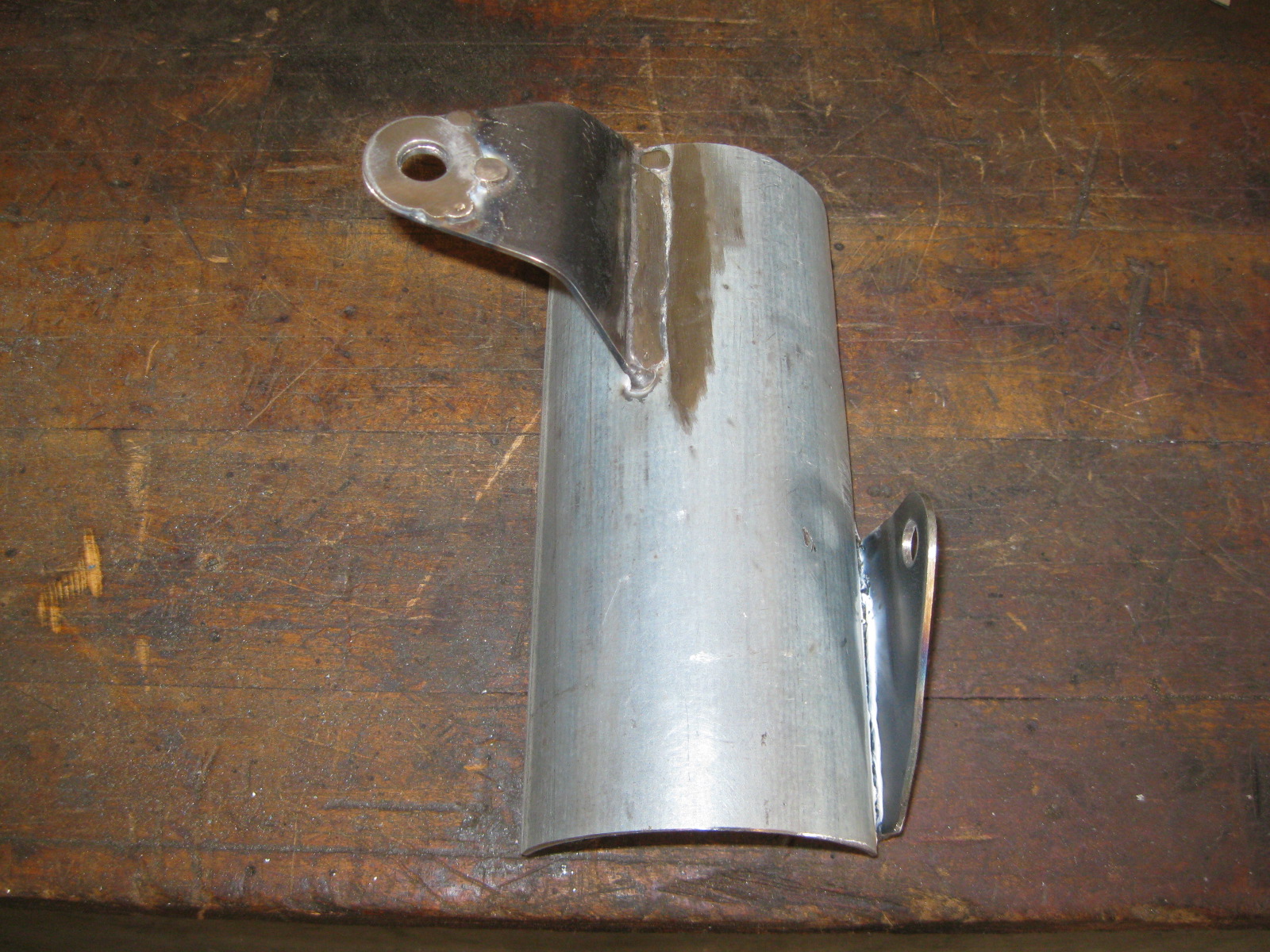
Also added this heat shield to the manifold to help keep the heat off the AC lines:
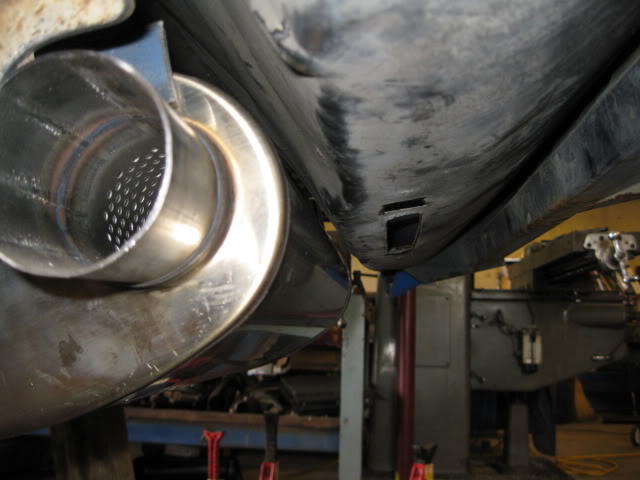
While I had the stainless wire in the mig, I also tacked the heat shield for the muffler in place as well:
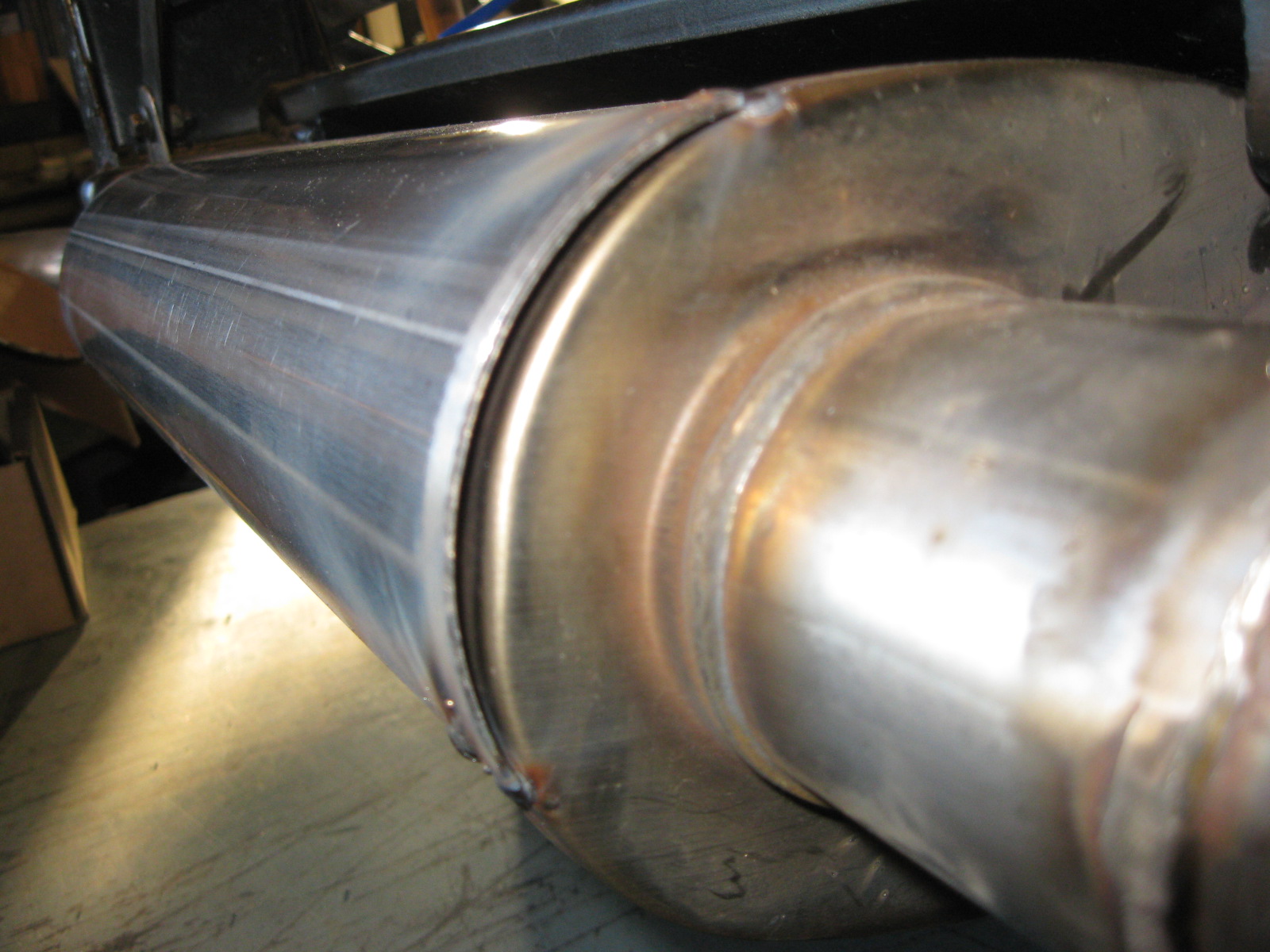
Here is a mock up picture of the muffler to trunk clearance. The heat shield should help everything stay cool at the bottom of the trunk:
I decided to route the hoses behind the manifold. Here is the stock position:
Here is is after being bent:
Also added this heat shield to the manifold to help keep the heat off the AC lines:
While I had the stainless wire in the mig, I also tacked the heat shield for the muffler in place as well:
Here is a mock up picture of the muffler to trunk clearance. The heat shield should help everything stay cool at the bottom of the trunk:
09-30-2012, 12:15 PM
#38
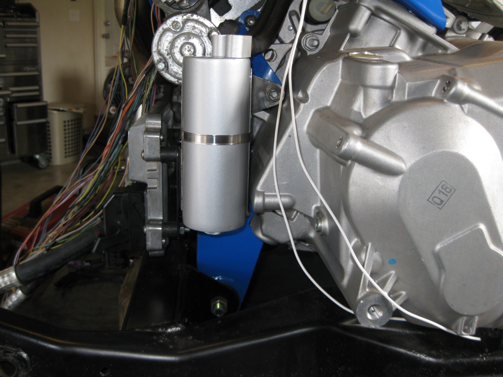
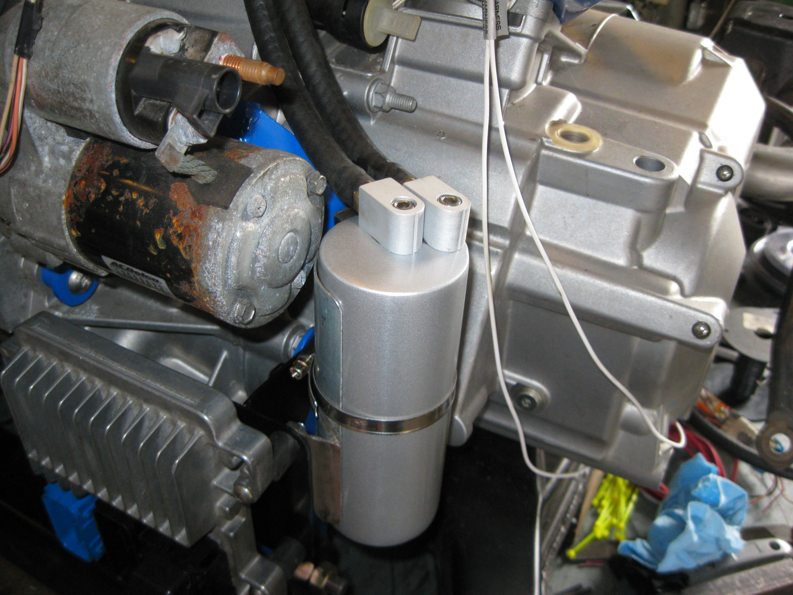
I wanted to run a catch can, but didn't want to see it, so I fabbed up this bracket and mounted it here:
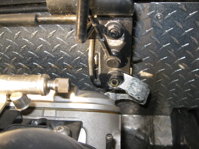
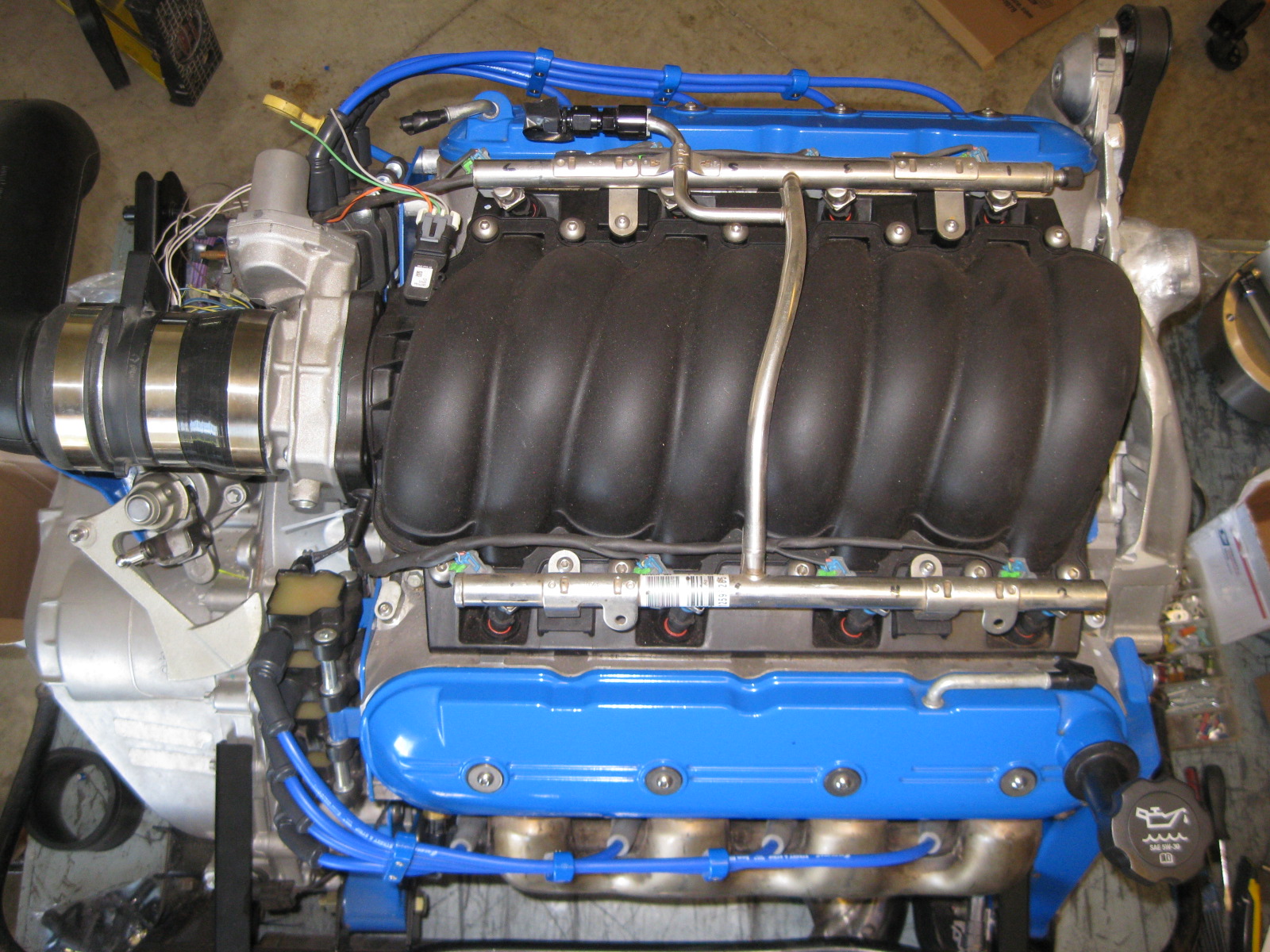
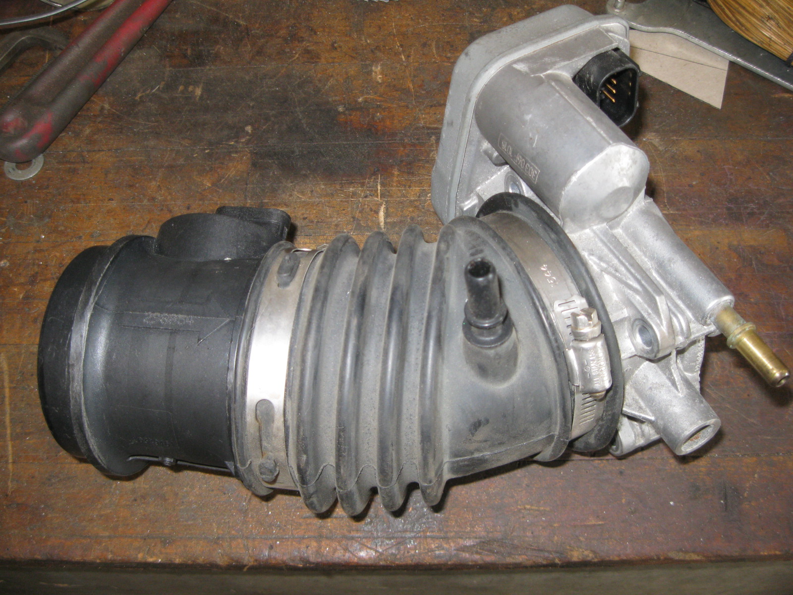
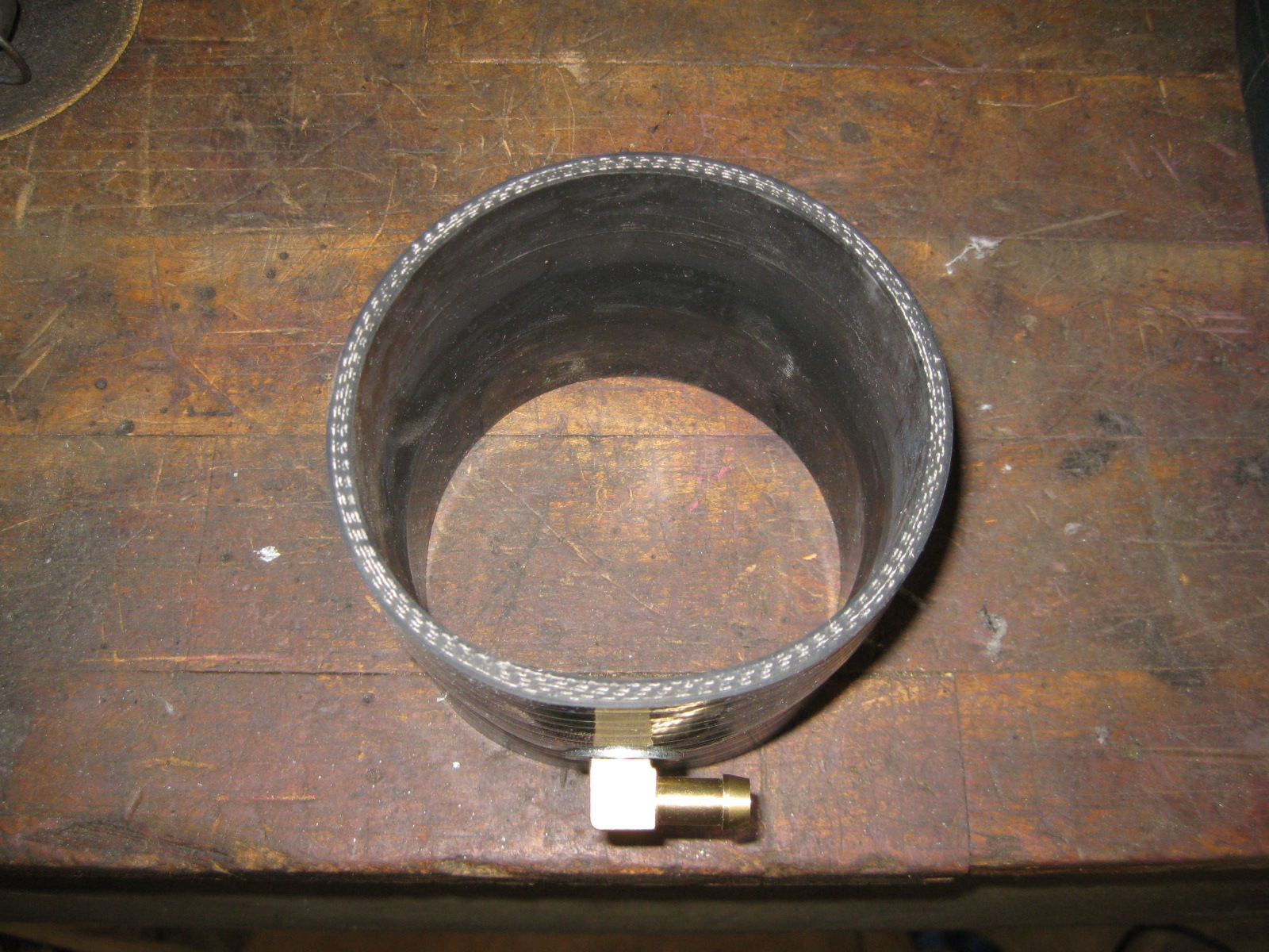
Since the LS4 tooks its fresh air supply for the PCV system between the MAF and the TB. I needed to do something similar with the silicone coupler. Here is the stock LS4 Maf, coupler with PCV port, and TB:
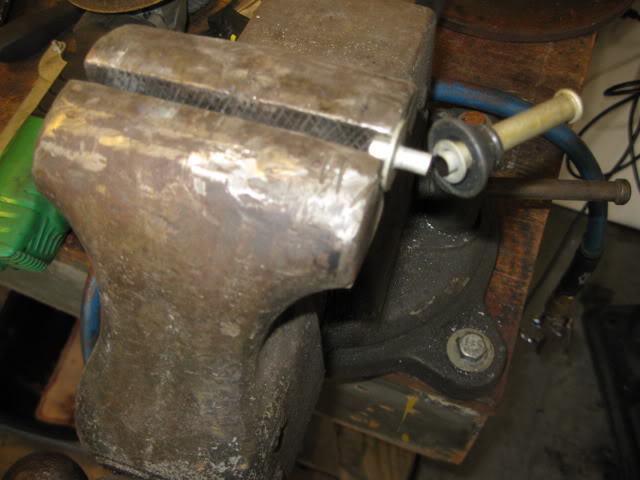
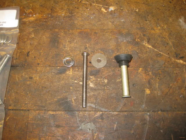
To get the needed PCV port in the silicone coupler, I found a 90 degree brass elbow, two washers (one that slid over the thread, one that didn't), tapped the washer with the smaller ID for the pipe thread (for use as a nut), drilled a hole in the silicone and then with some RTV and loc-tite installed the hose nipple.
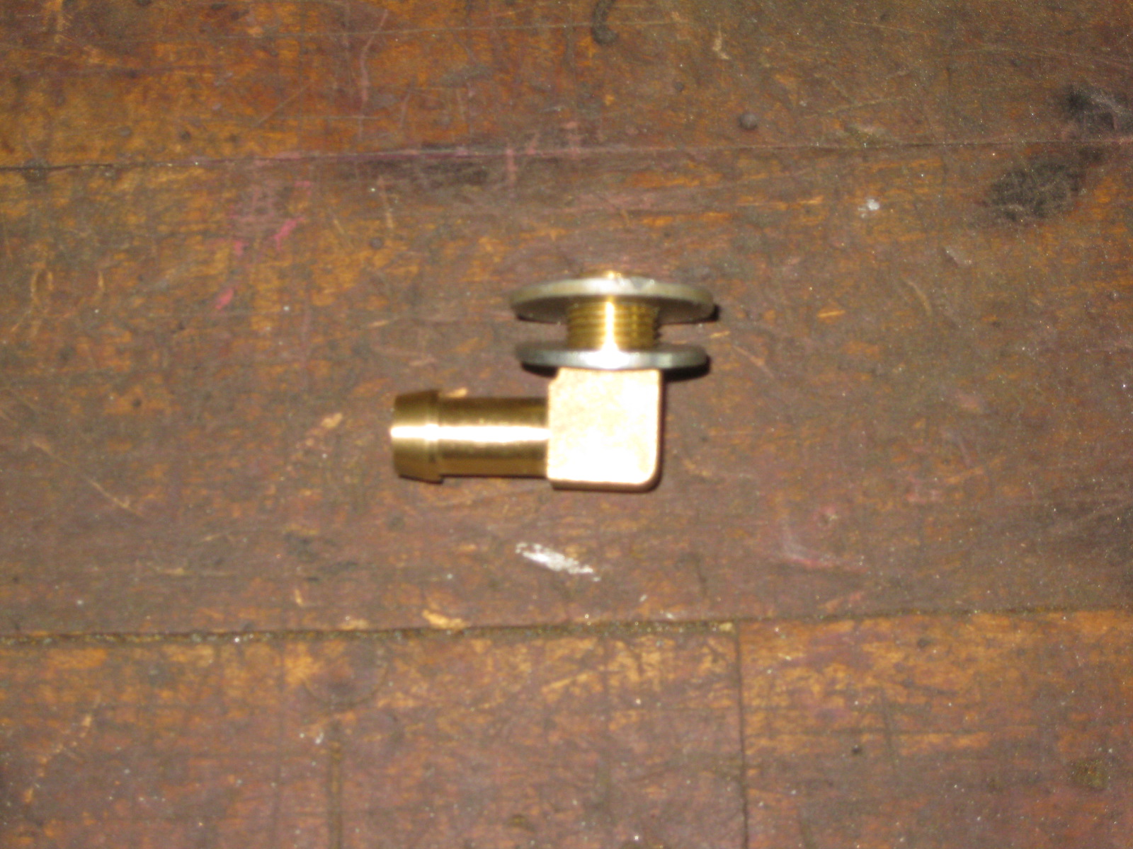
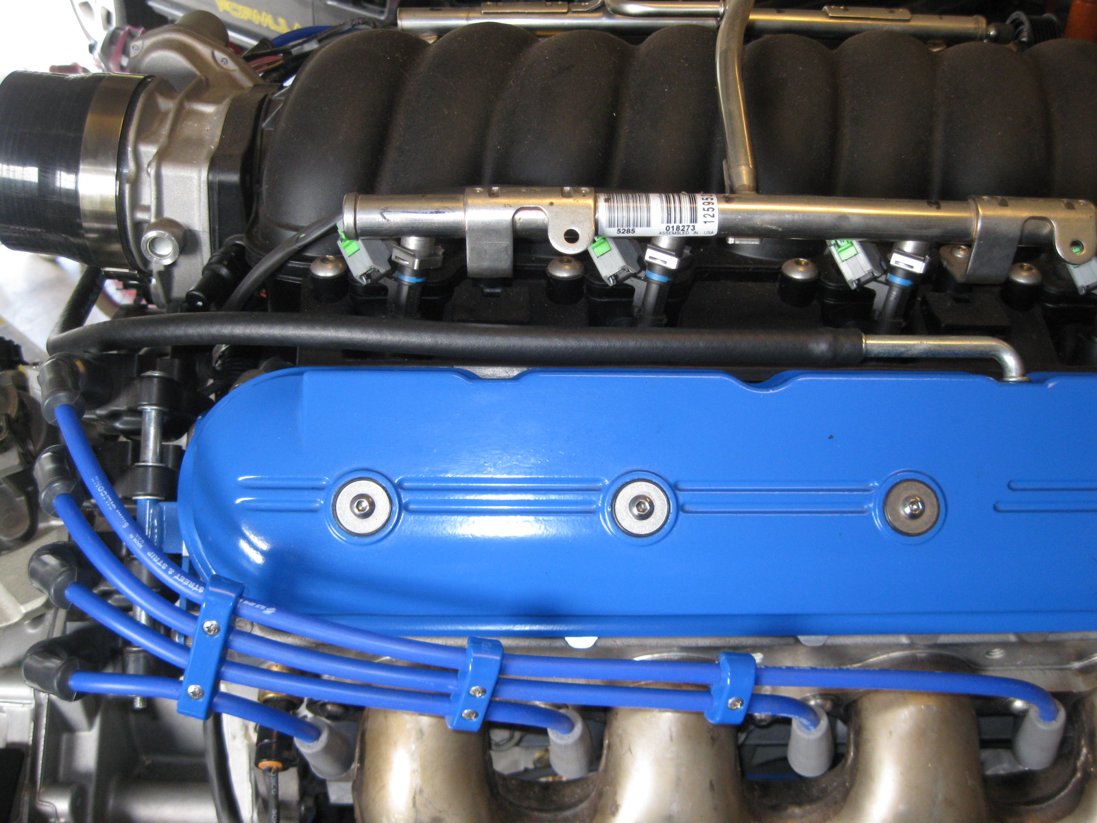
I am not completely happy with the hose running along the valve cover (its not perfectly parallel with the valve cover), so I might replace it with some aluminum hard line, or run a hard line inside the hose so it will hold its shape.
Since the LS4 tooks its fresh air supply for the PCV system between the MAF and the TB. I needed to do something similar with the silicone coupler. Here is the stock LS4 Maf, coupler with PCV port, and TB:
To get the needed PCV port in the silicone coupler, I found a 90 degree brass elbow, two washers (one that slid over the thread, one that didn't), tapped the washer with the smaller ID for the pipe thread (for use as a nut), drilled a hole in the silicone and then with some RTV and loc-tite installed the hose nipple.
I am not completely happy with the hose running along the valve cover (its not perfectly parallel with the valve cover), so I might replace it with some aluminum hard line, or run a hard line inside the hose so it will hold its shape.
09-30-2012, 12:24 PM
#39
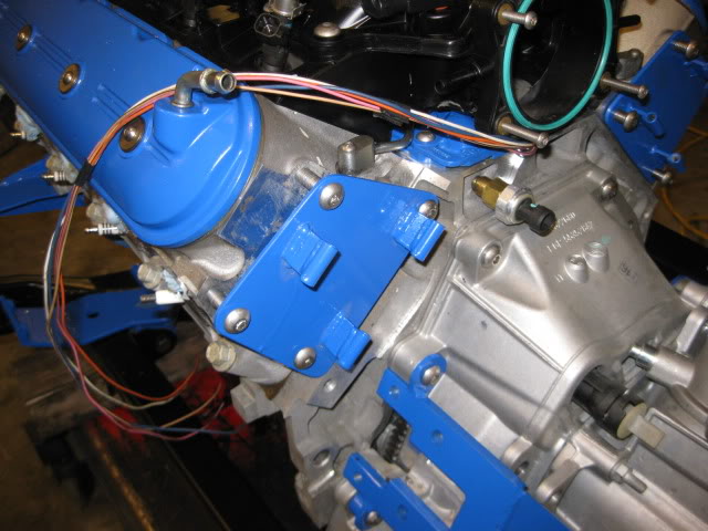
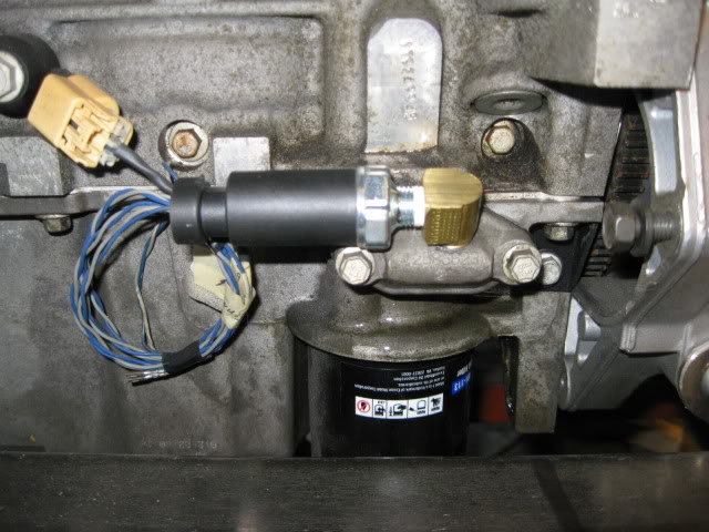
To run the stock fiero oil pressure gauge, I tapped the oil passage cover on the oil pan and mounted a second oil pressure sender for the Fiero gauge.
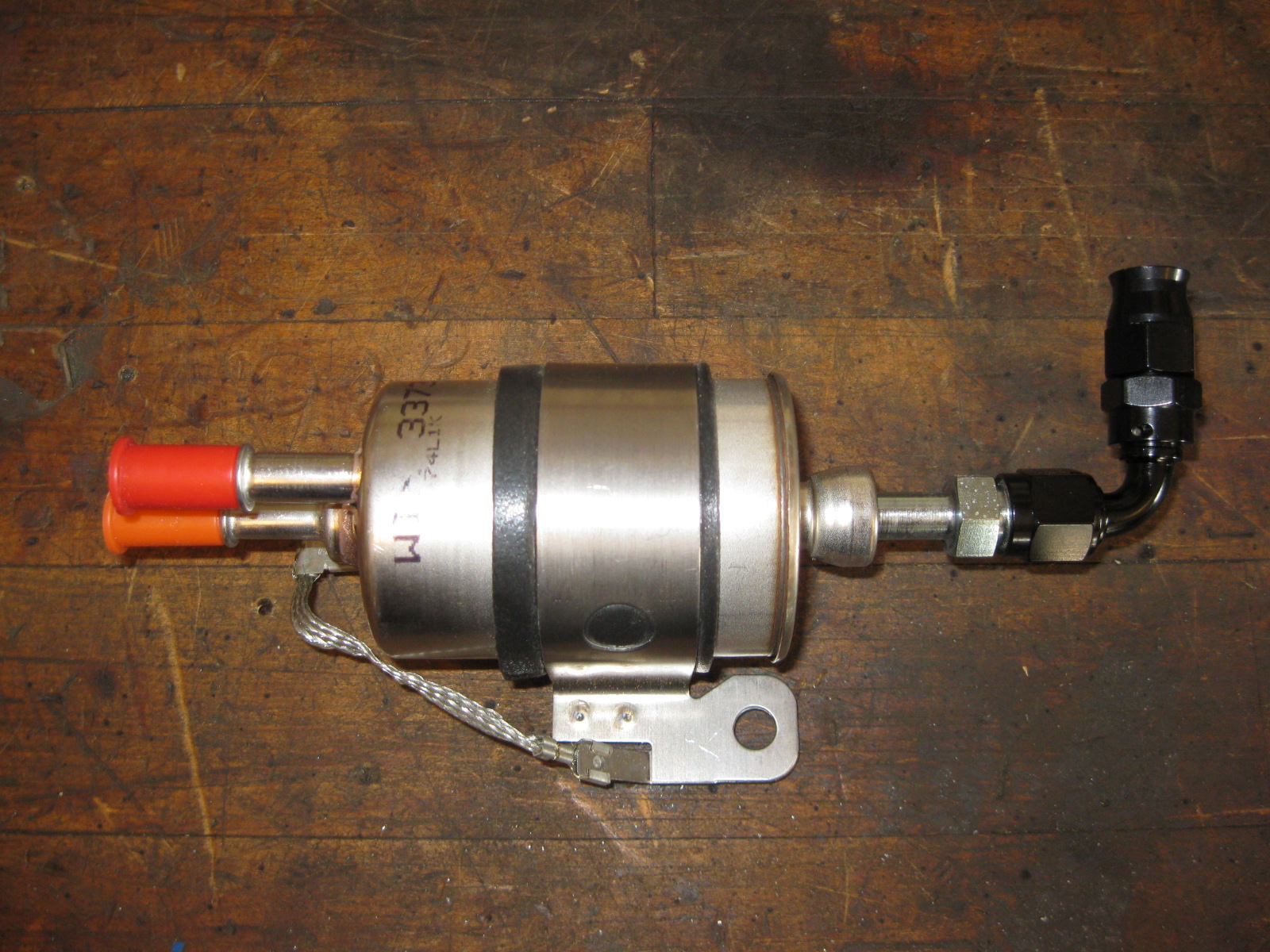
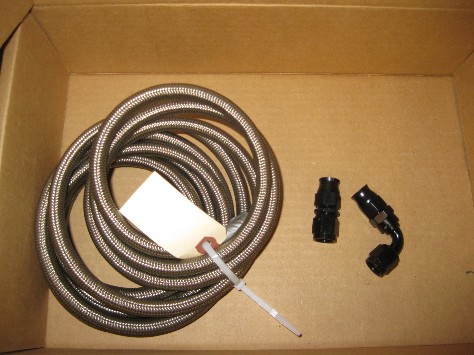
For the fuel system, I picked up some braided PTFE fuel line, fittings and the filter/bypass to convert to the returnless fuel setup:
For the coolant hoses, this is a rough approximation of how they will run.
For the fuel system, I picked up some braided PTFE fuel line, fittings and the filter/bypass to convert to the returnless fuel setup:
For the coolant hoses, this is a rough approximation of how they will run.
