
88 Fiero Formula LS4/F40 6 speed swap
 05-29-2016, 08:30 PM
#221


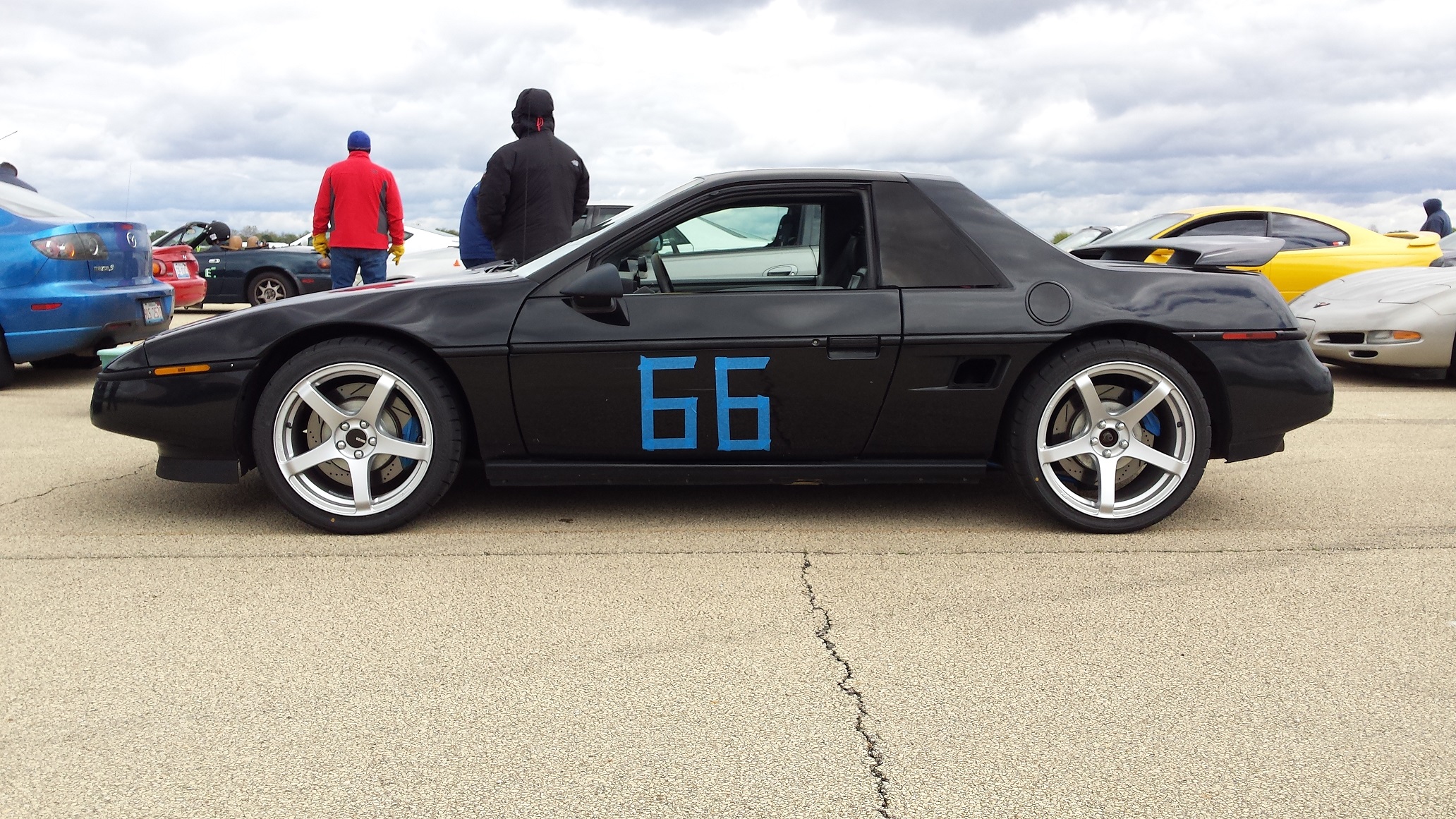
Here are a couple of autocross videos breaking in the new wheels/tires. It was 48 degrees all day... burr... Eventually my skill will catch up with the car...
Then I put the car back in the garage for some interior work.
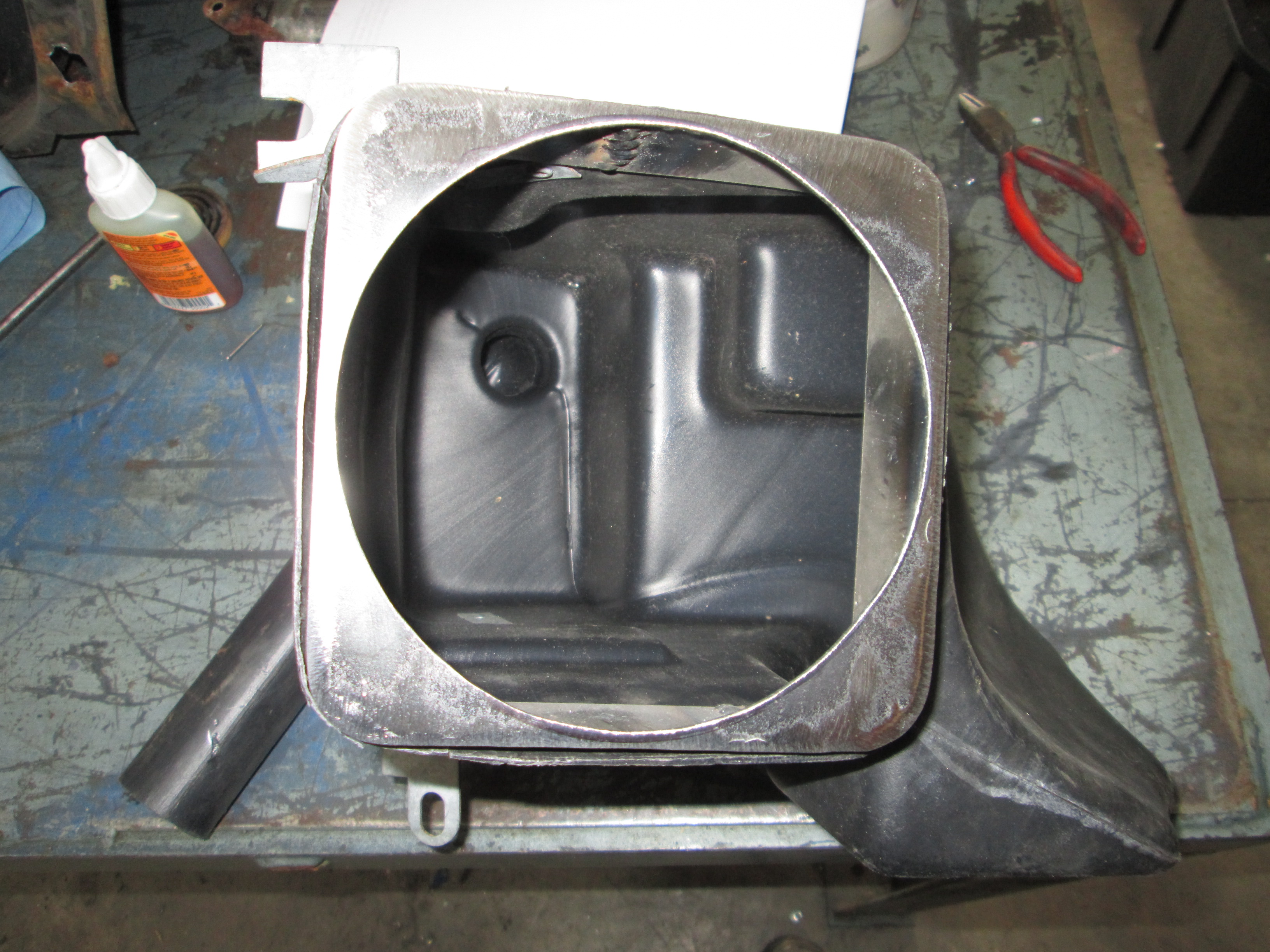
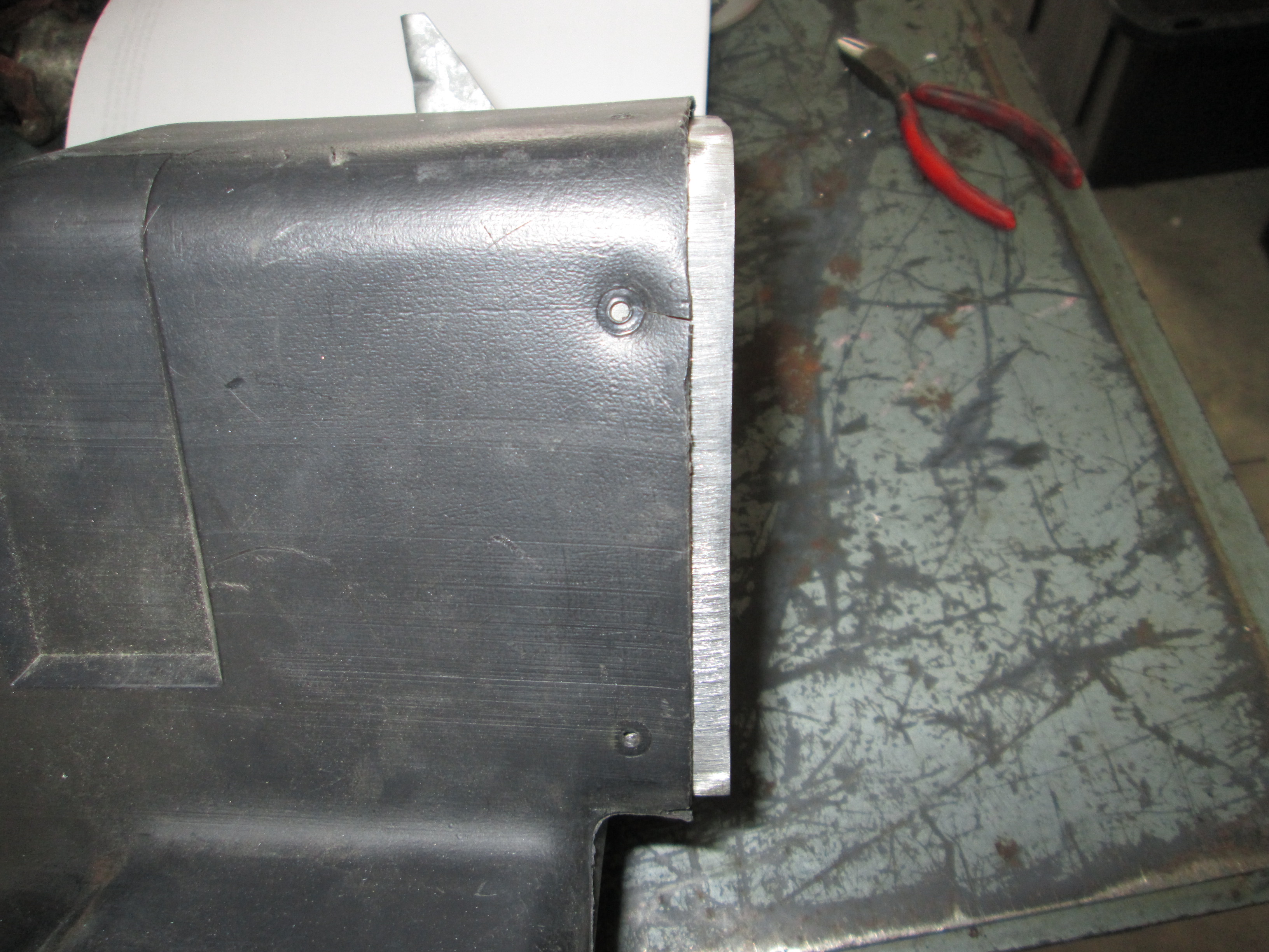
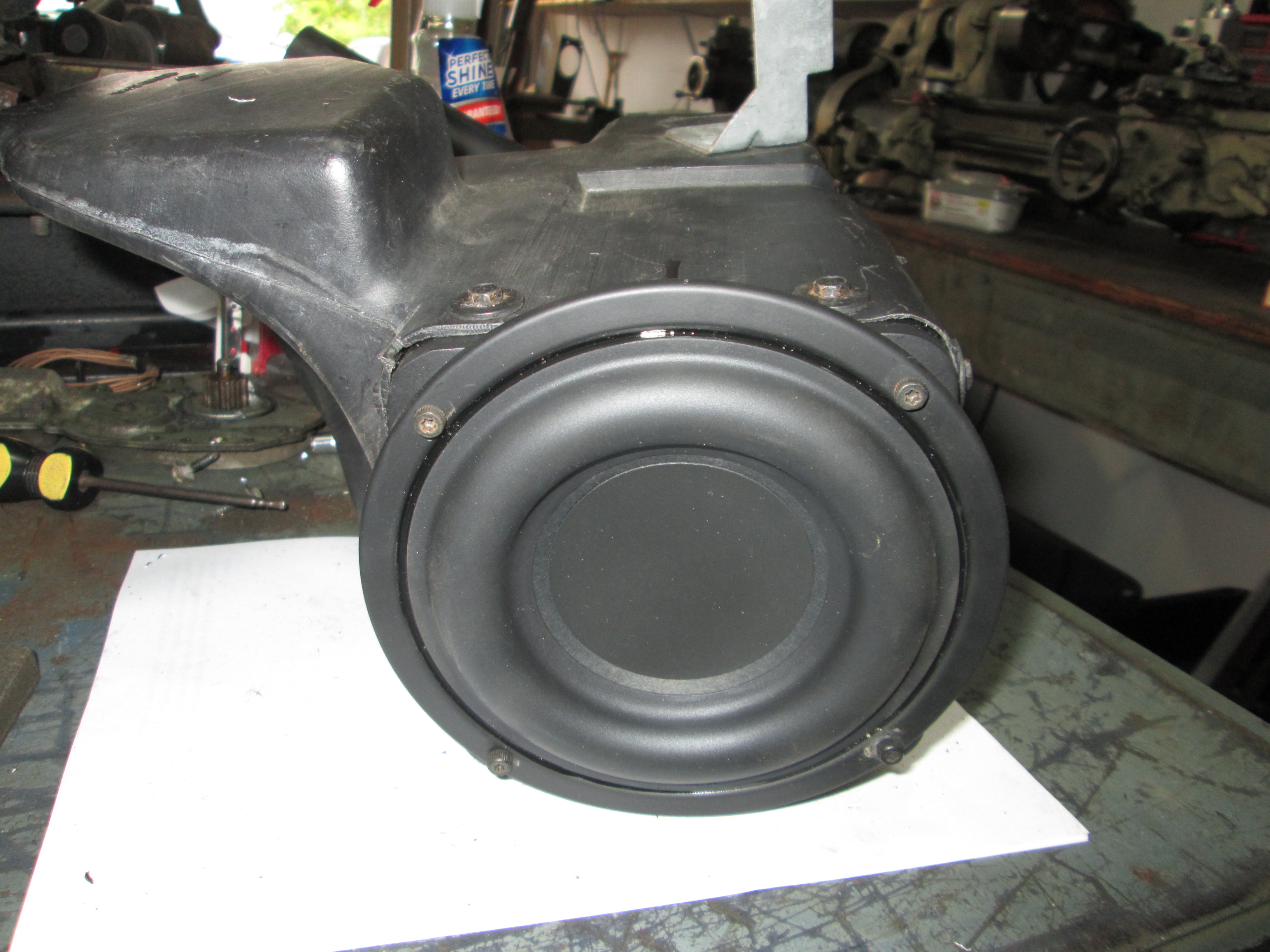
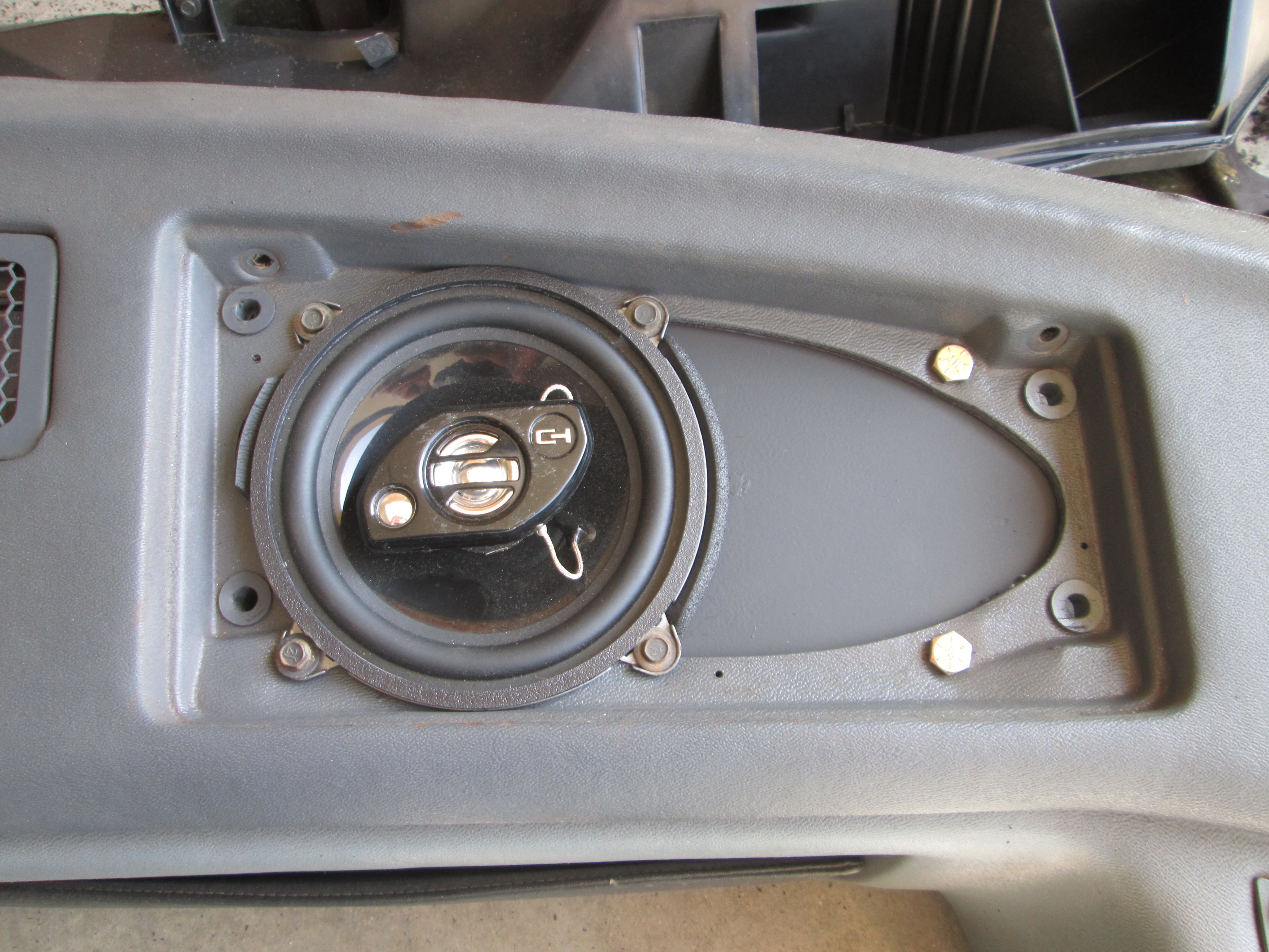
Fabbed up a 16ga steel ring to use a 5 1/4" Tang Bang sub in the stock fiero enclosure (4" factory sub):
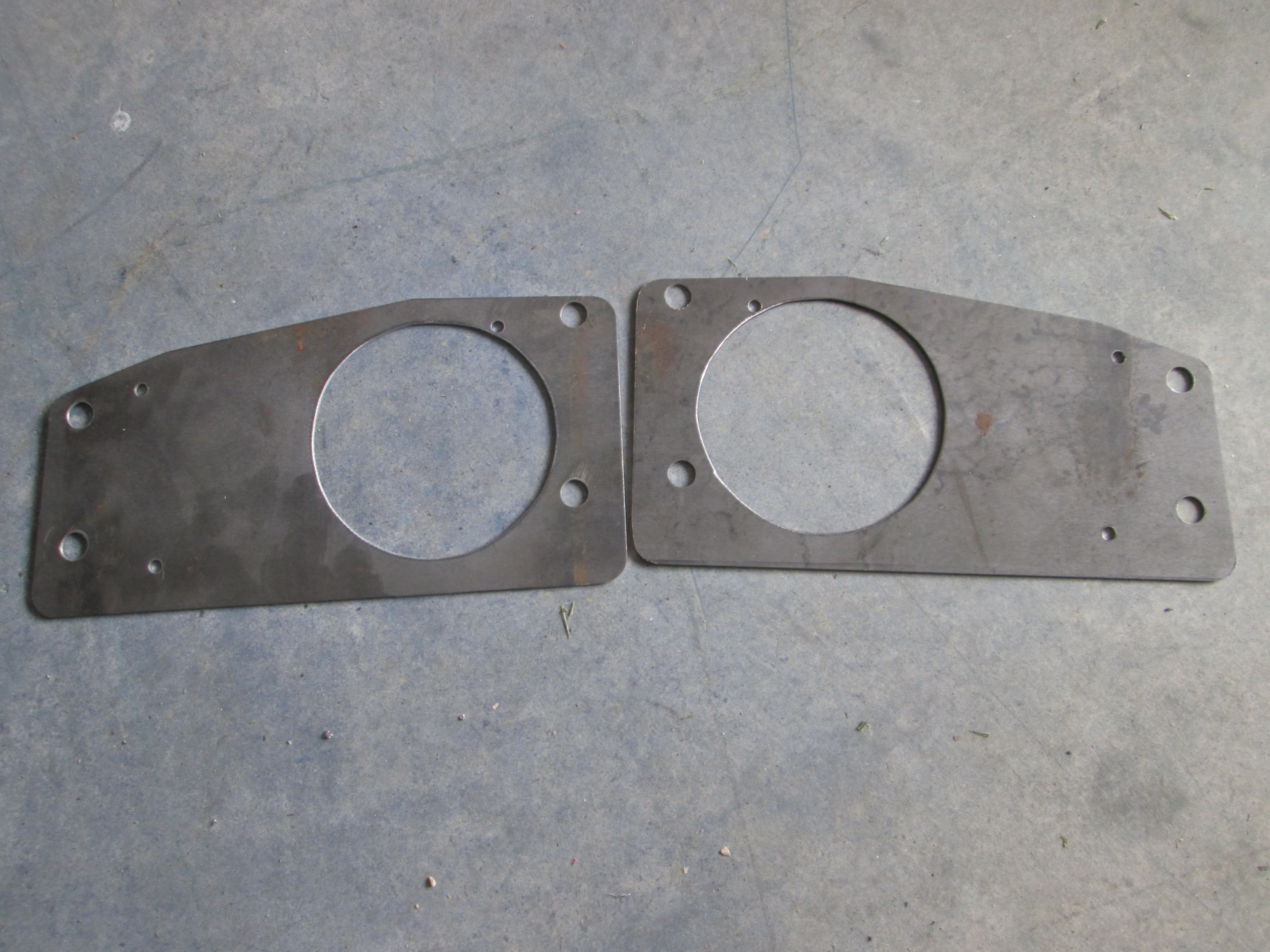
Also made some 16ga dash speaker plates to run 5 1/4 speakers in place of the 4x10.

Then I put the car back in the garage for some interior work.
Fabbed up a 16ga steel ring to use a 5 1/4" Tang Bang sub in the stock fiero enclosure (4" factory sub):
Also made some 16ga dash speaker plates to run 5 1/4 speakers in place of the 4x10.
Last edited by fieroguru; 05-29-2016 at 09:06 PM.
 05-29-2016, 08:44 PM
#222
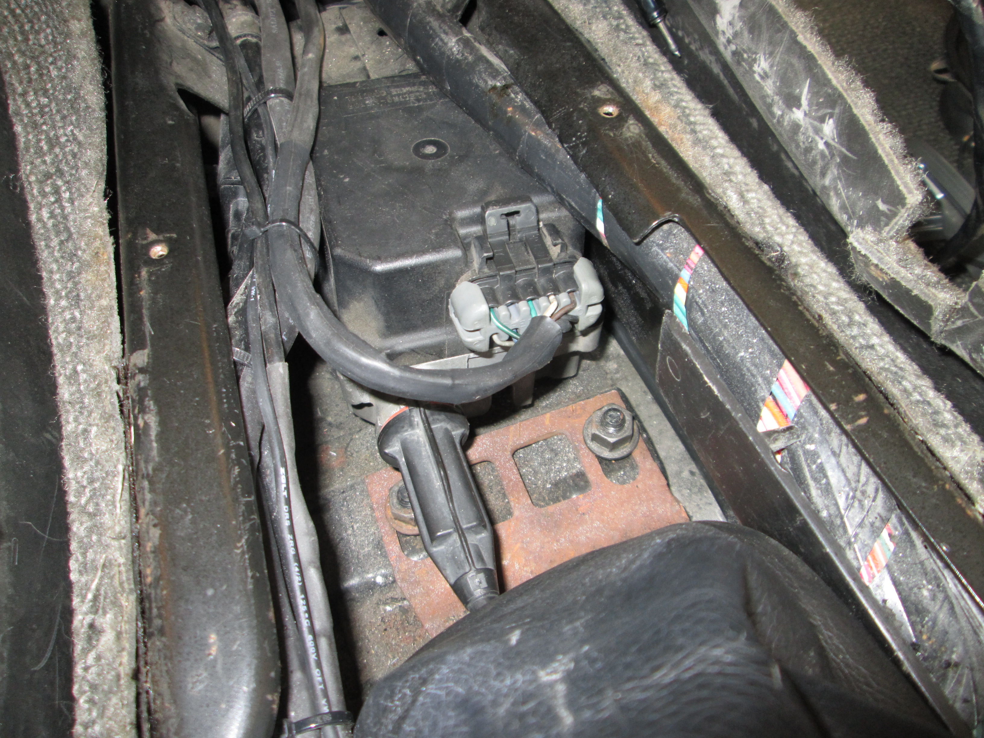
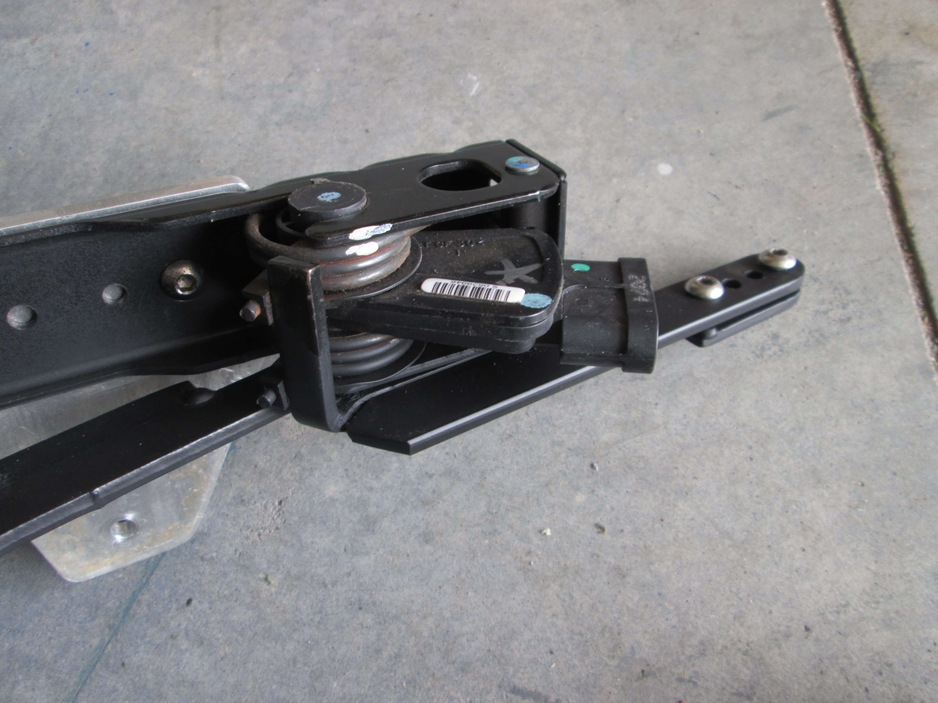
While the dash and interior were out, I went ahead and did a few more things. To make room for the factory subwoofer housing, I had to relocated the AR cruise module to the center console and reworked the pedal bracket to give my size 12s a little more toe room.
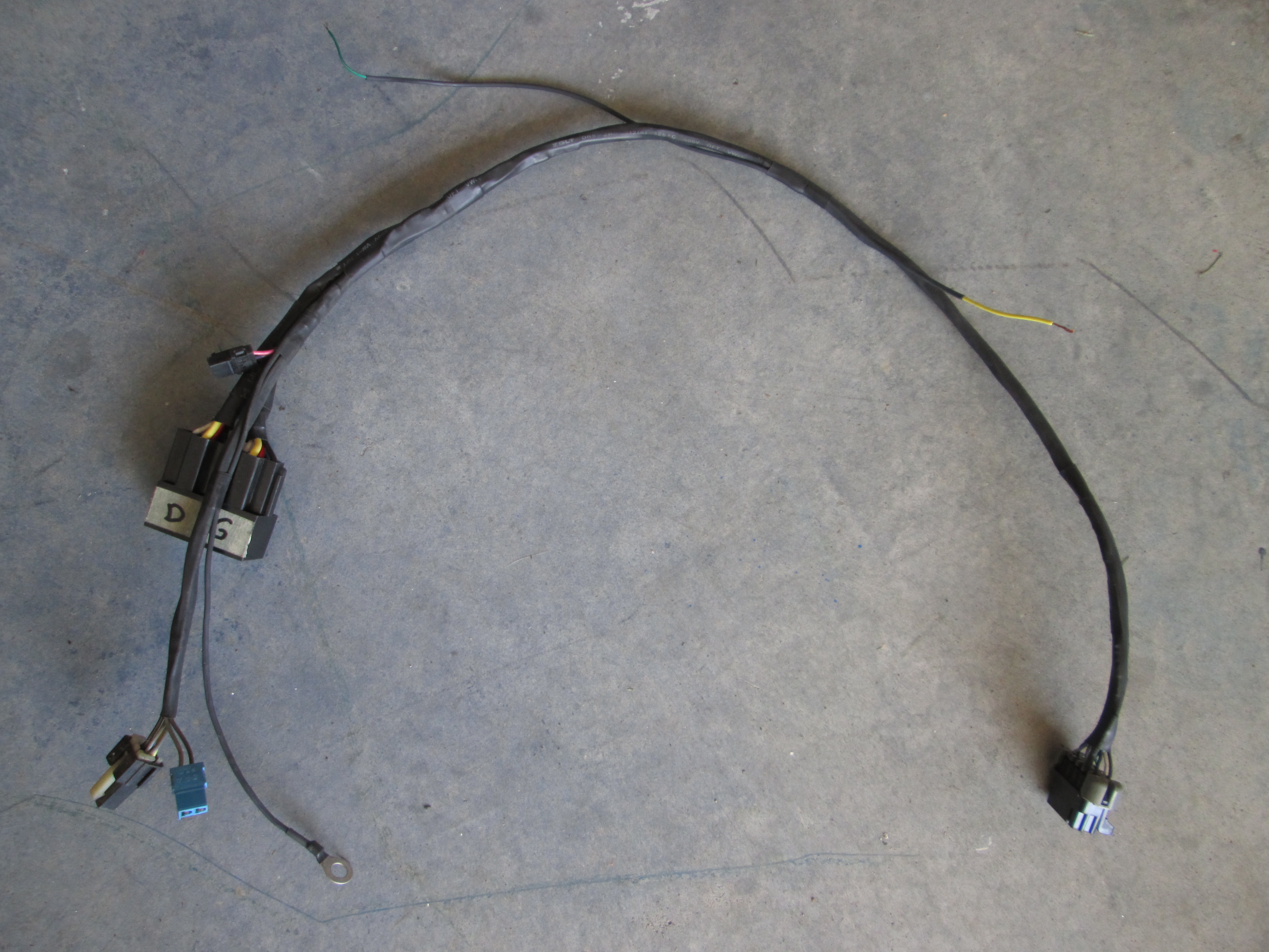
I even reworked the harness to make it shorter/simpler:
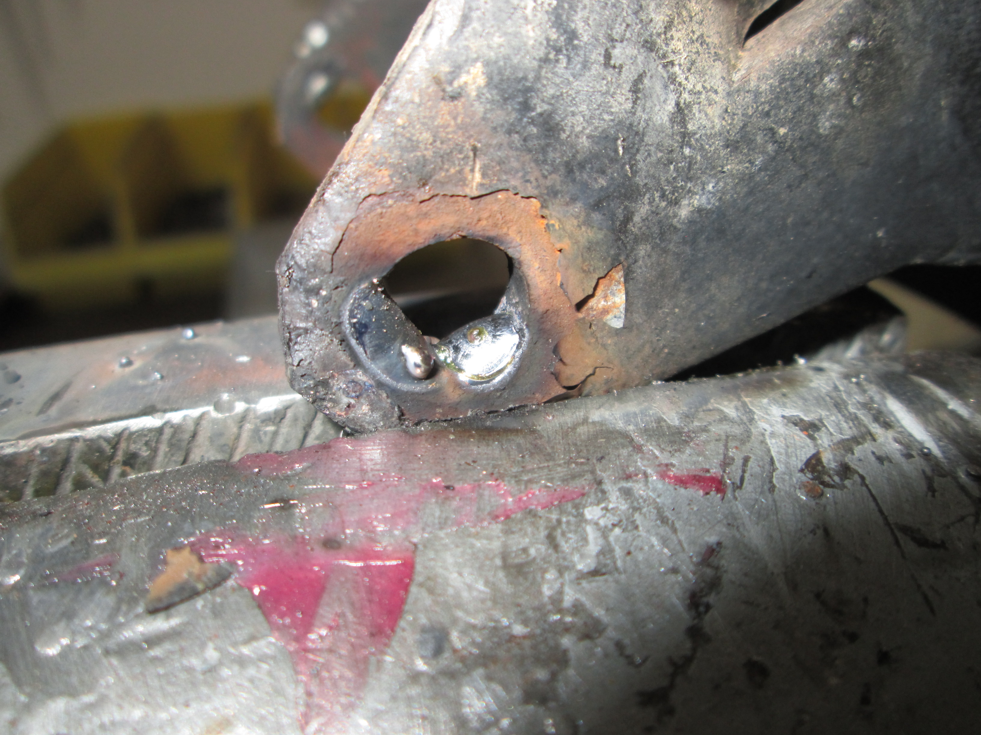
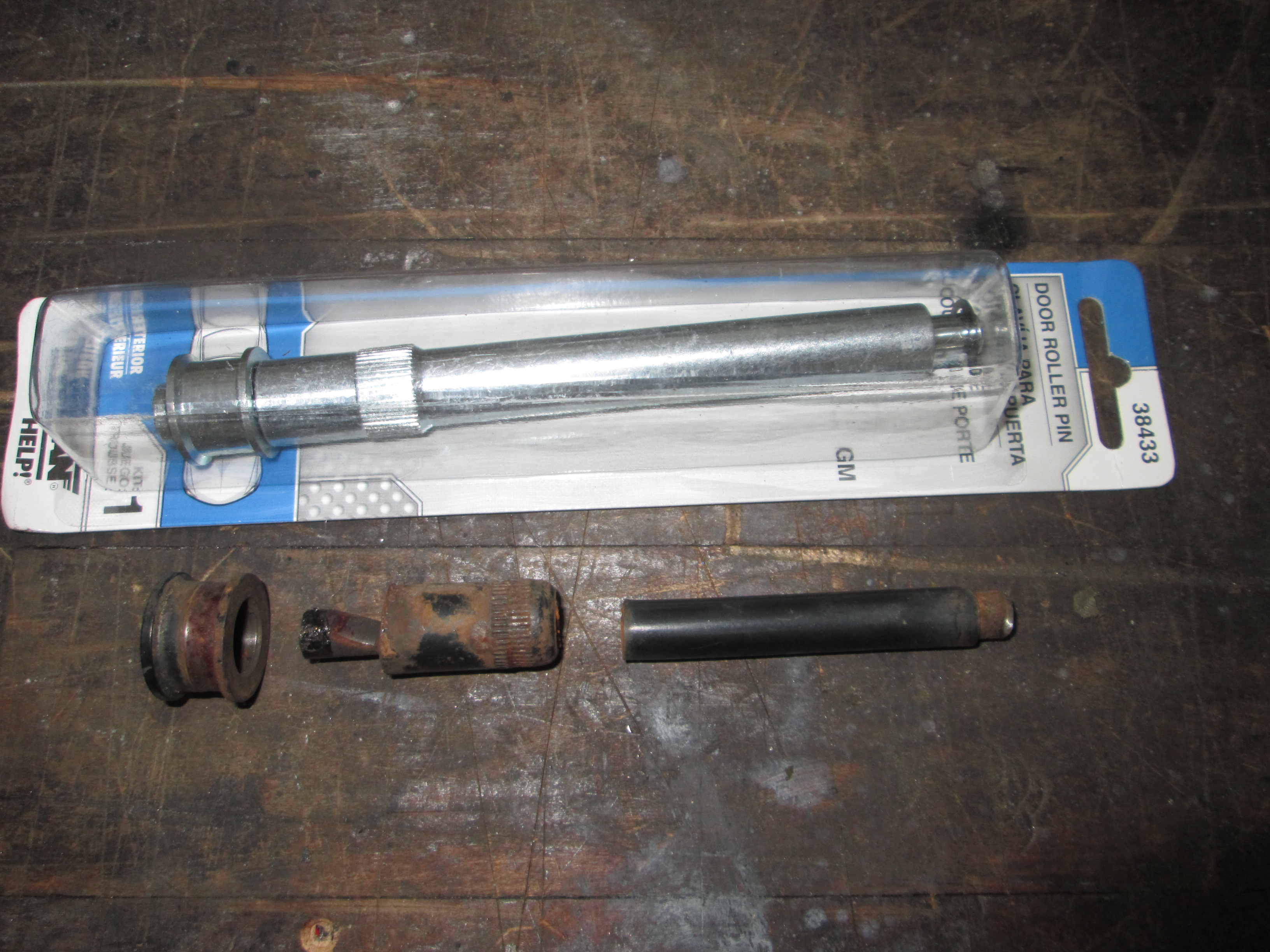
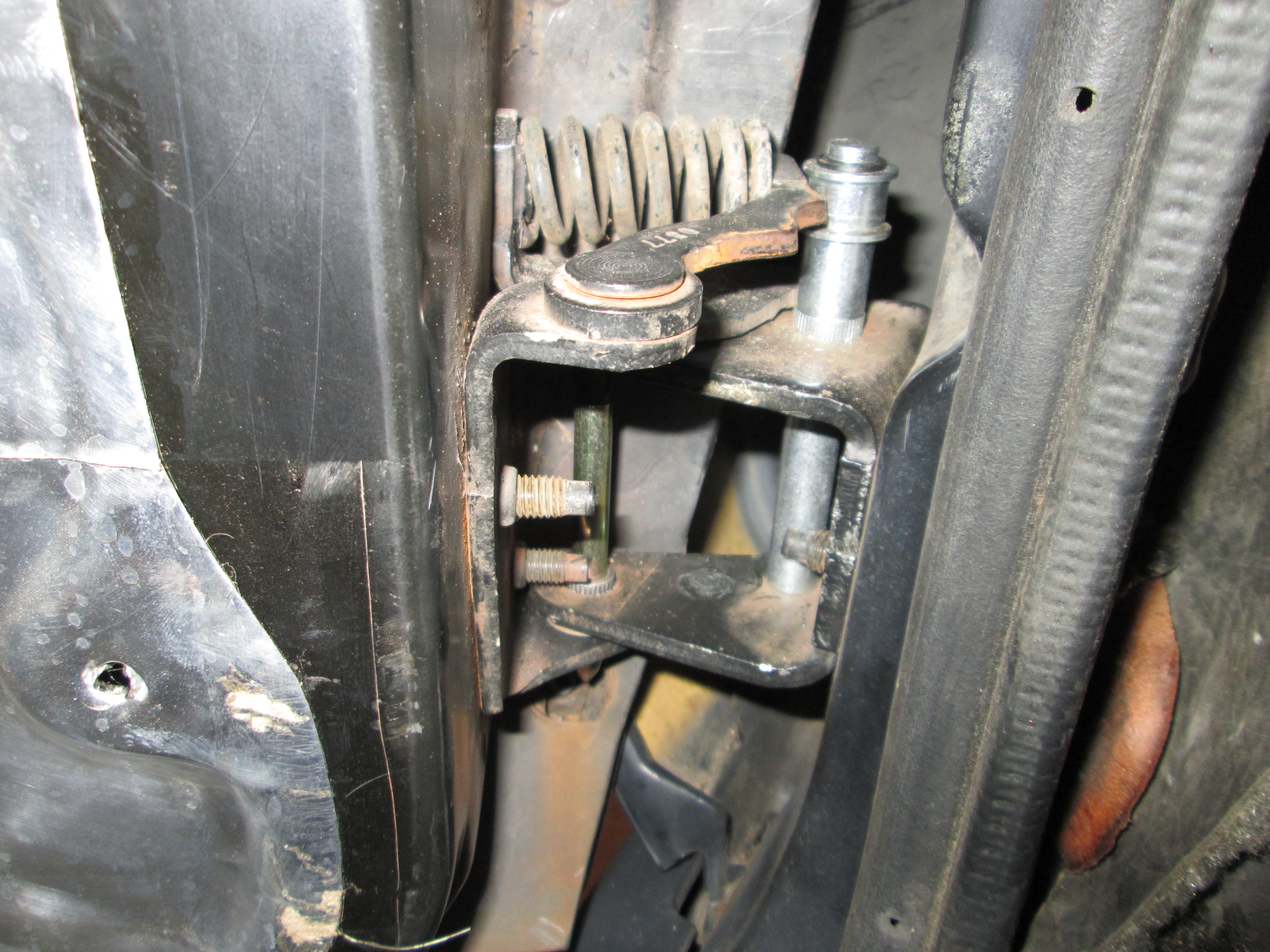
I rebuilt the door hinges on the driver side. New bushings helped, but the other part of the hinge had a lot of slop in the holes. So I built them up with tack welds and filed them back to size. The DS door also needed a new door detent pin... old one snapped off. So I had to modify the closest one I could find to make it shorter.
I also removed the hand cranks and scissor cams and converted the car to factory PW/PL with factory harness and parts. However, Fieros have really slow windows, so while doing the swap I installed Rodney Dickman's motor upgrade kit. It uses later model motors with more torque and less gear reduction, so they are faster!
I even reworked the harness to make it shorter/simpler:
I rebuilt the door hinges on the driver side. New bushings helped, but the other part of the hinge had a lot of slop in the holes. So I built them up with tack welds and filed them back to size. The DS door also needed a new door detent pin... old one snapped off. So I had to modify the closest one I could find to make it shorter.
I also removed the hand cranks and scissor cams and converted the car to factory PW/PL with factory harness and parts. However, Fieros have really slow windows, so while doing the swap I installed Rodney Dickman's motor upgrade kit. It uses later model motors with more torque and less gear reduction, so they are faster!
05-29-2016, 08:53 PM
#223
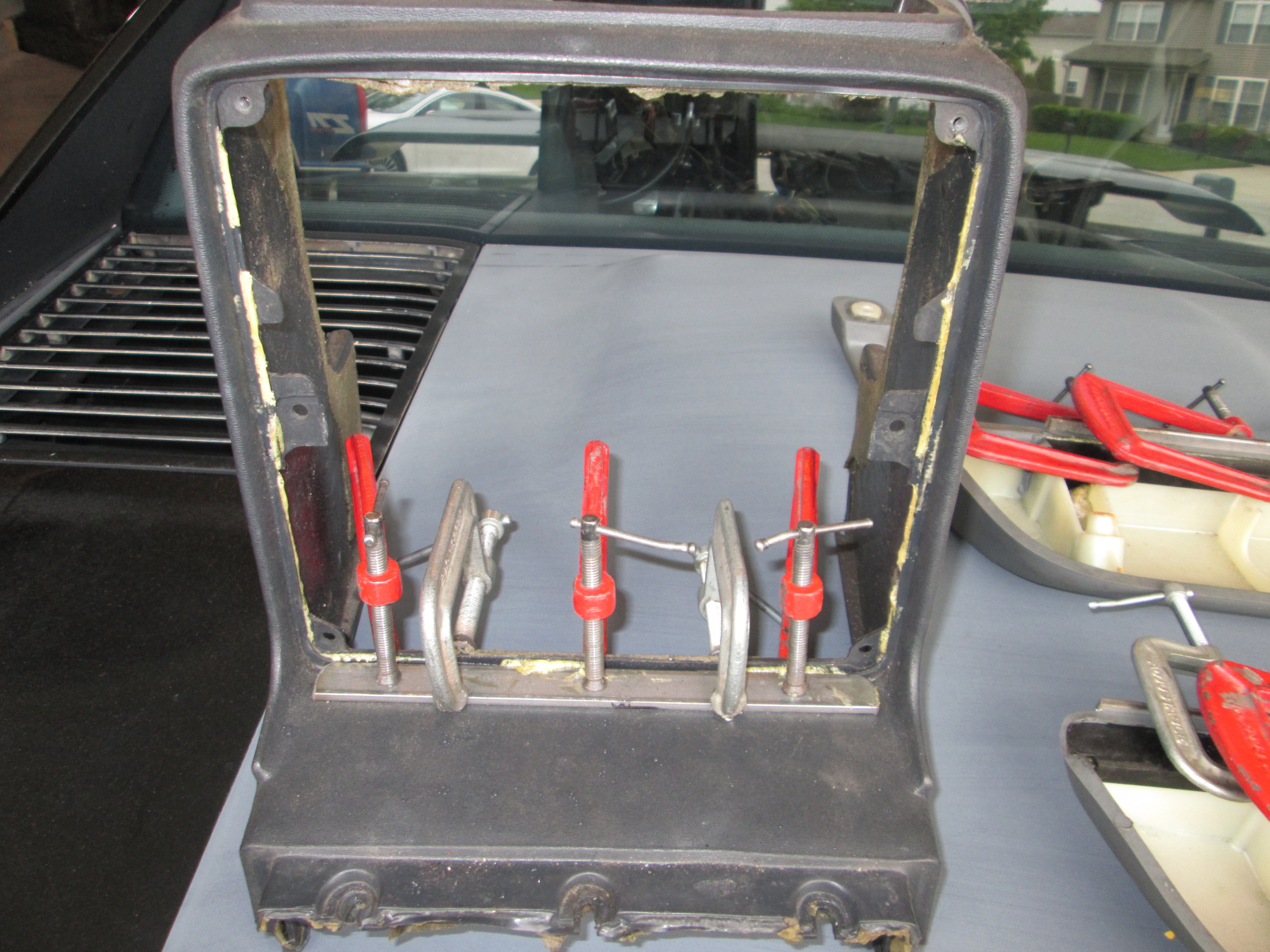
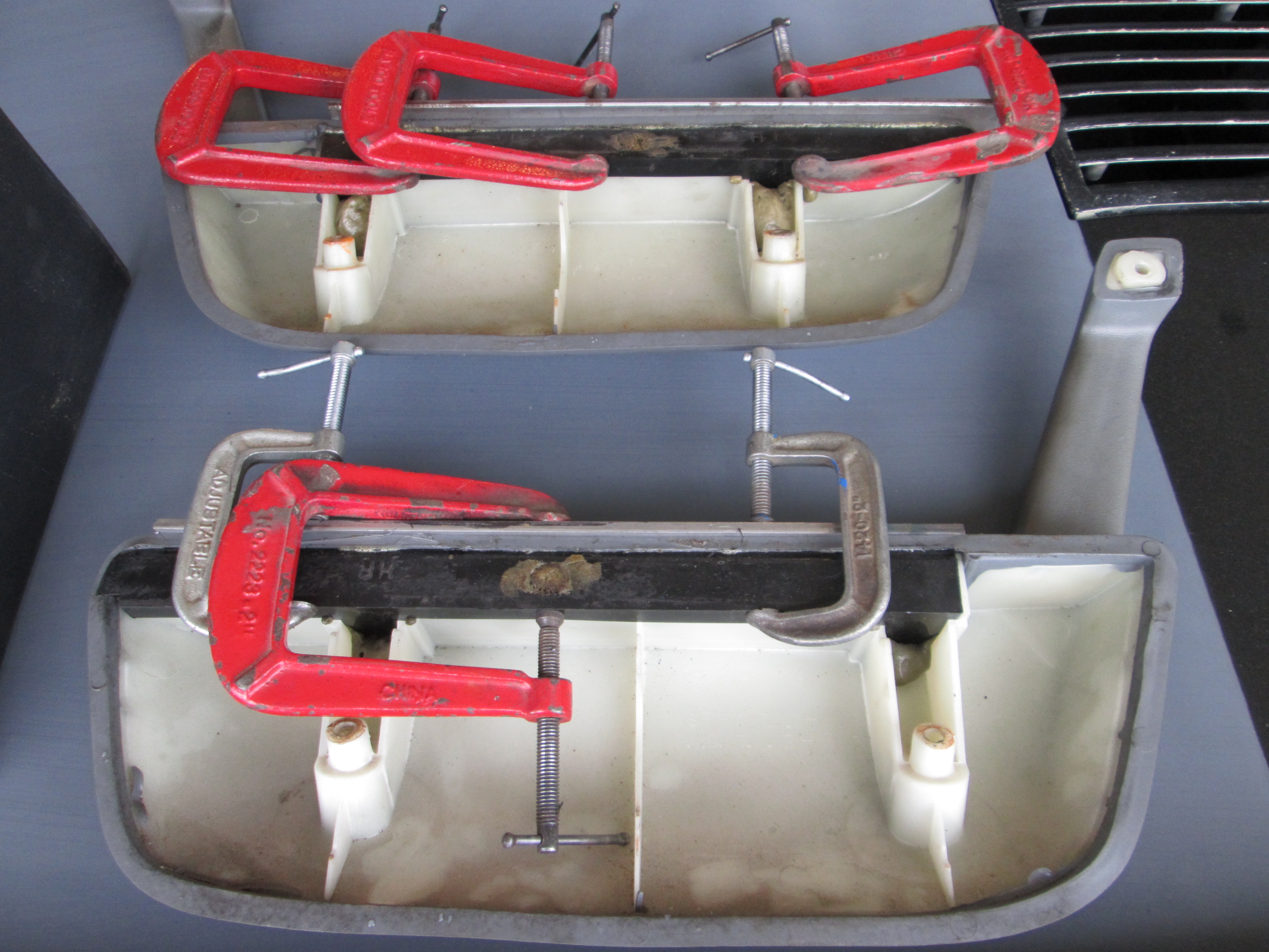
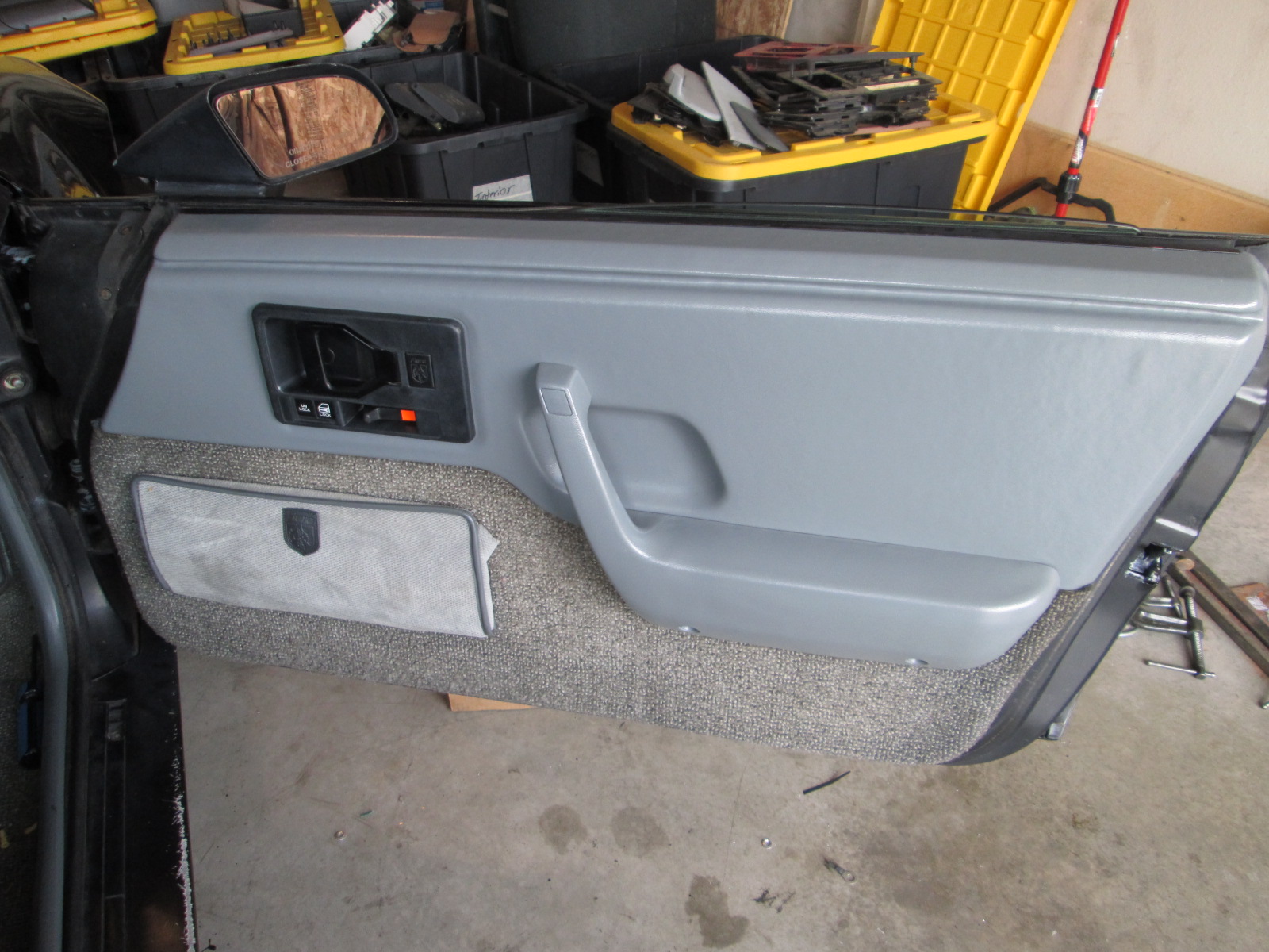
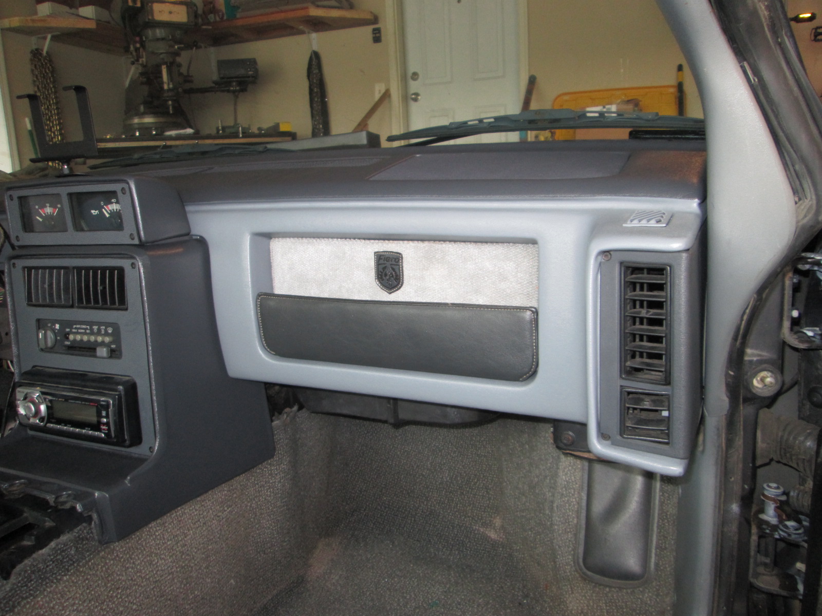
The PW required different door panels, and the dash and most interior parts were out... so why not improve the looks of those too!
Fiero interior warps and starts to peal from the edges... so glue, metal, and clamps to get it back closer to original:

Painted the dash, door panels, and other instrument cluster/console items.
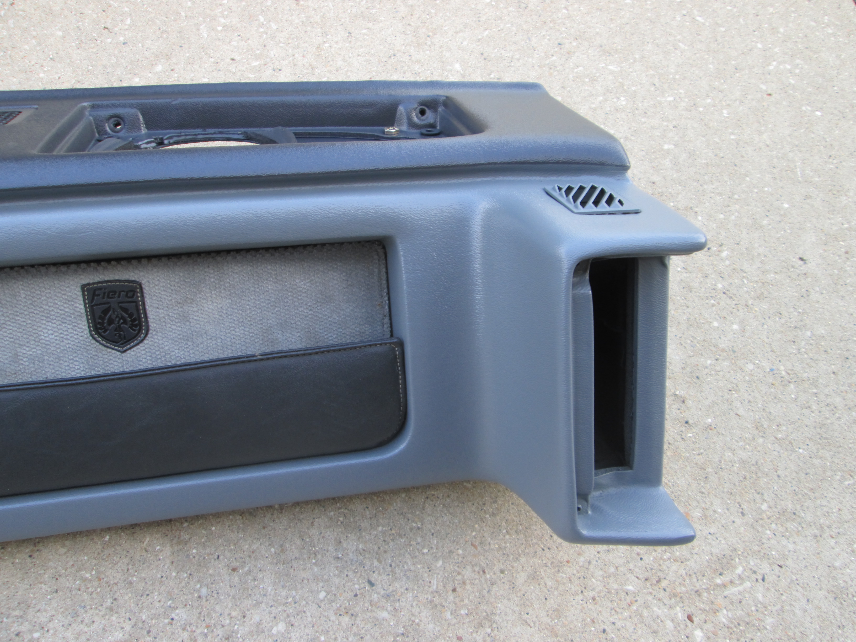
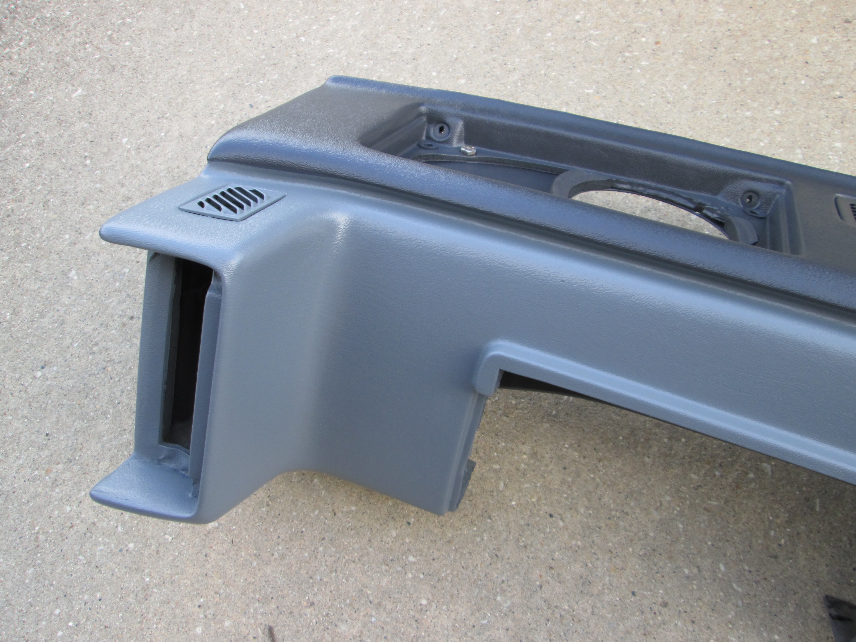

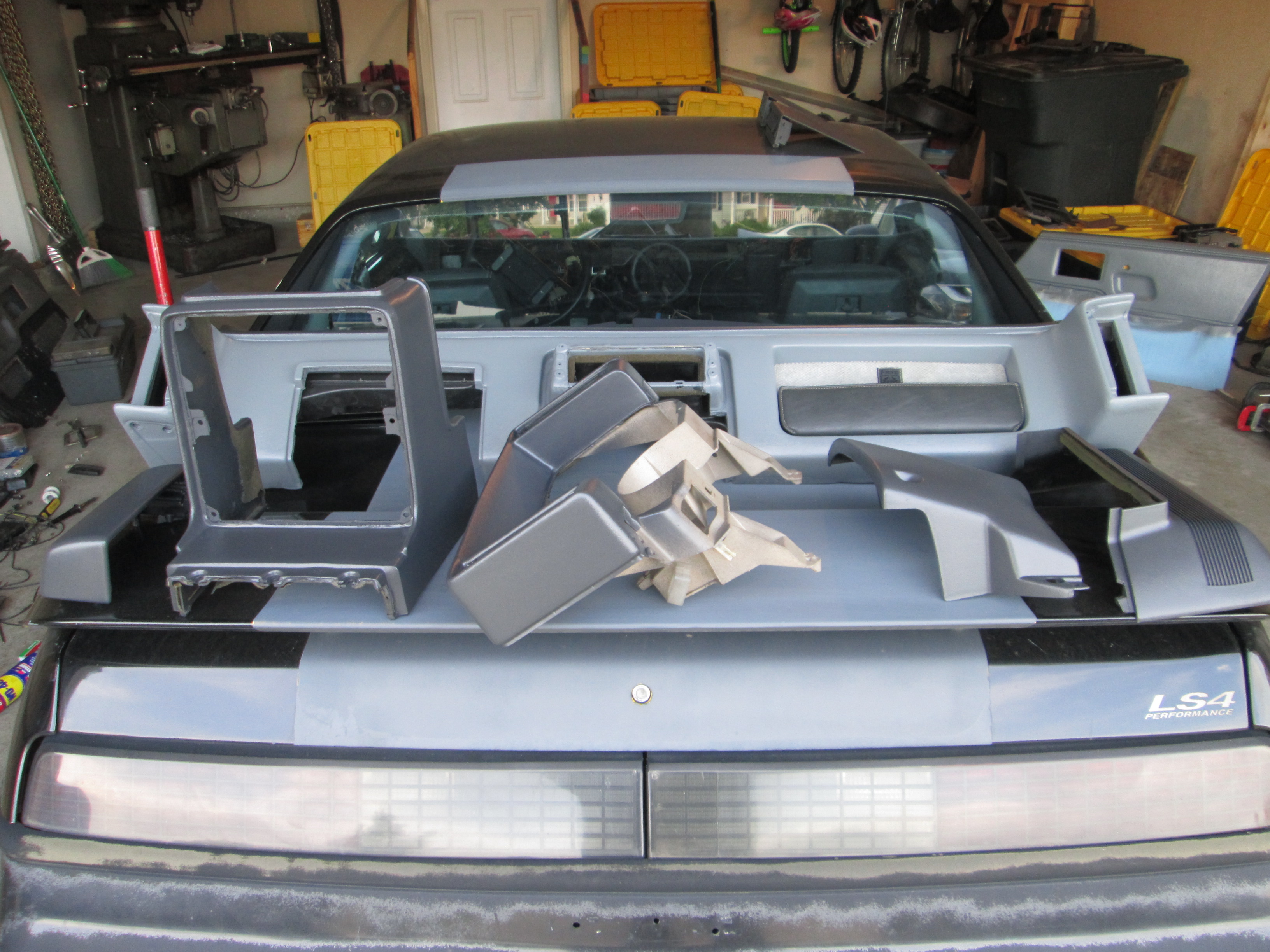
Looks much better:
Fiero interior warps and starts to peal from the edges... so glue, metal, and clamps to get it back closer to original:
Painted the dash, door panels, and other instrument cluster/console items.
Looks much better:
05-29-2016, 08:57 PM
#224
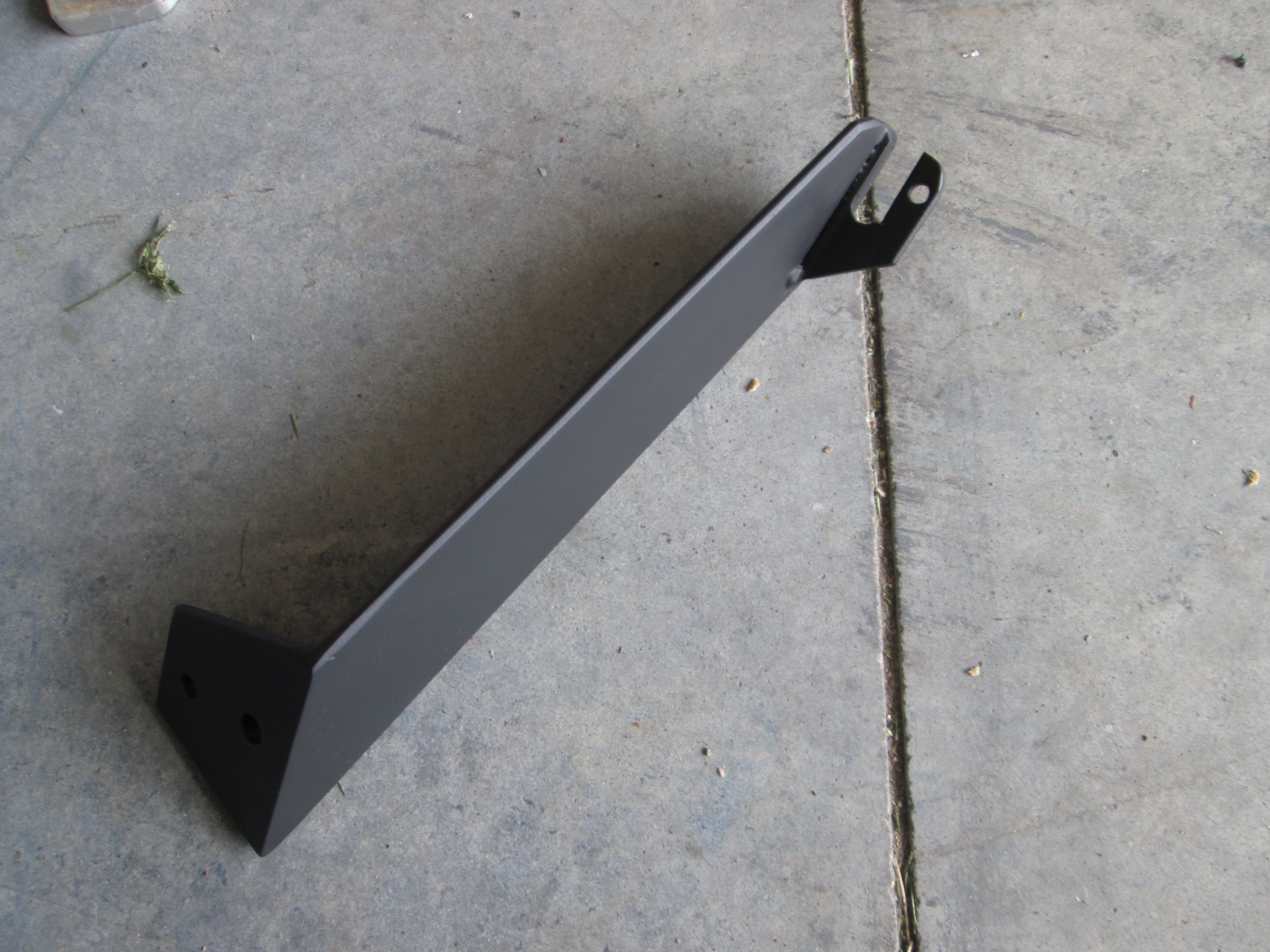
Once the interior was mostly done and I was back driving the car, spent a full day working on the tensioner arm upgrade... just a few more tweaks and it will be complete.
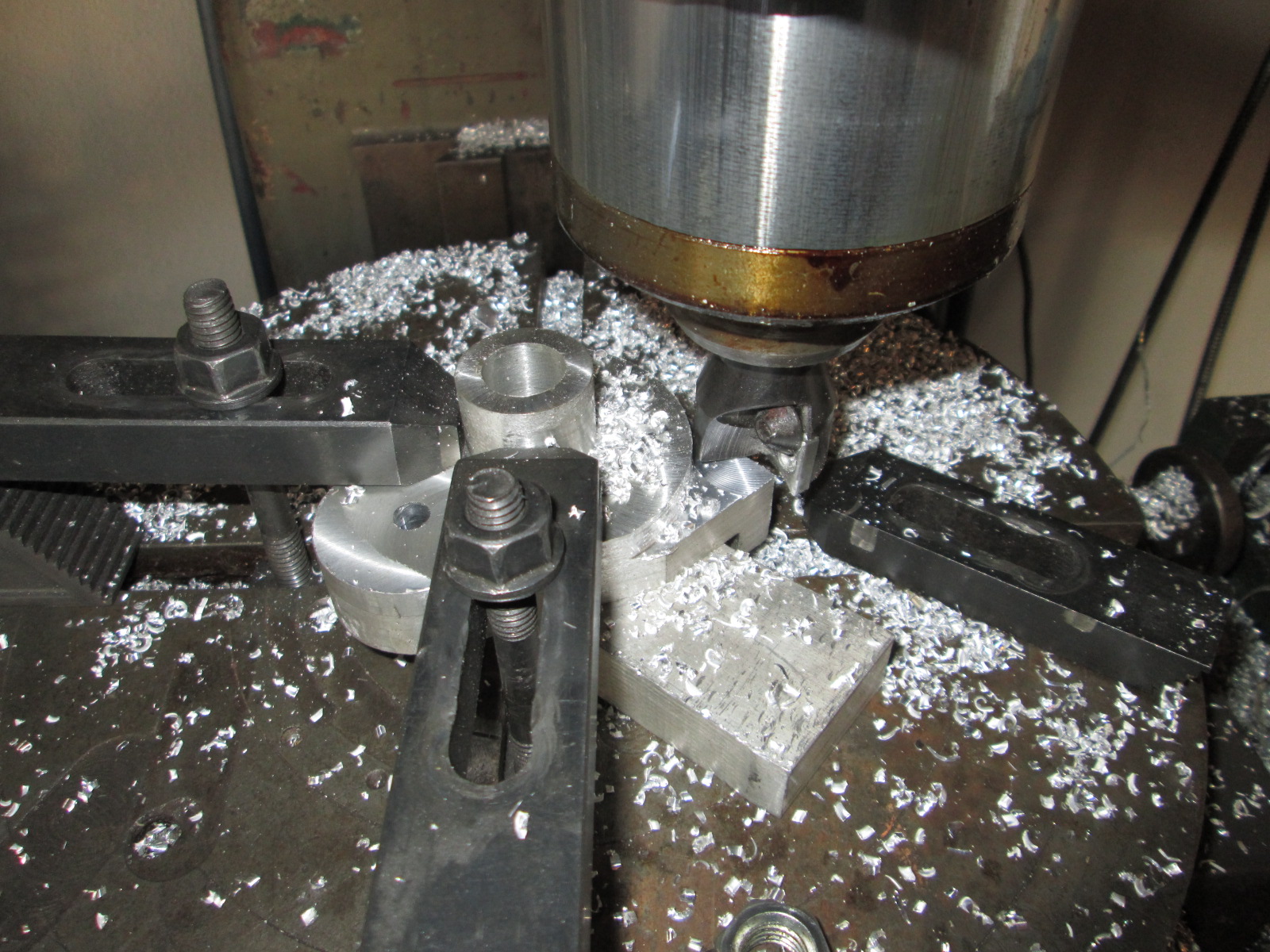
Lots of individual setups with the mill and rotary table...

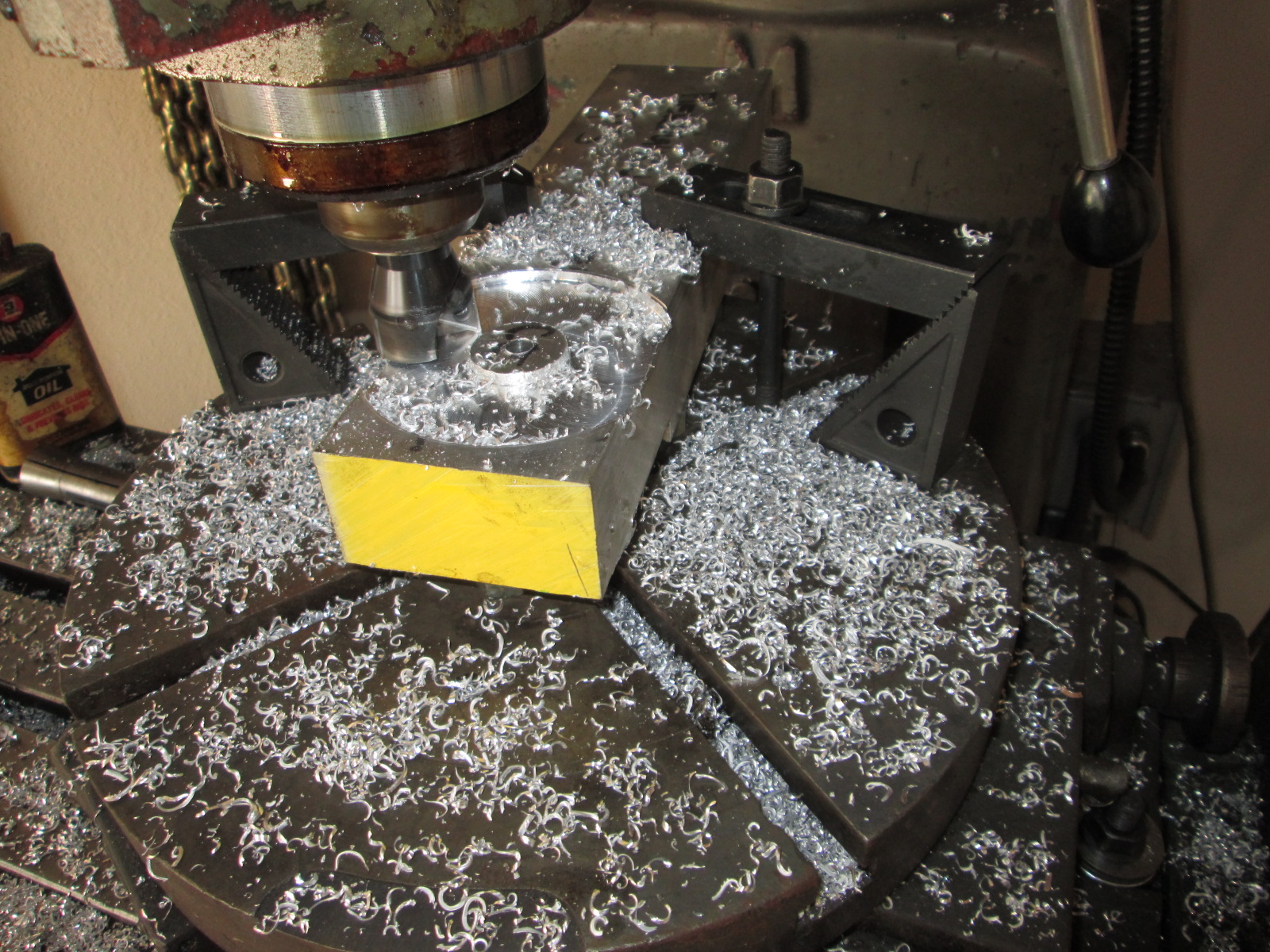

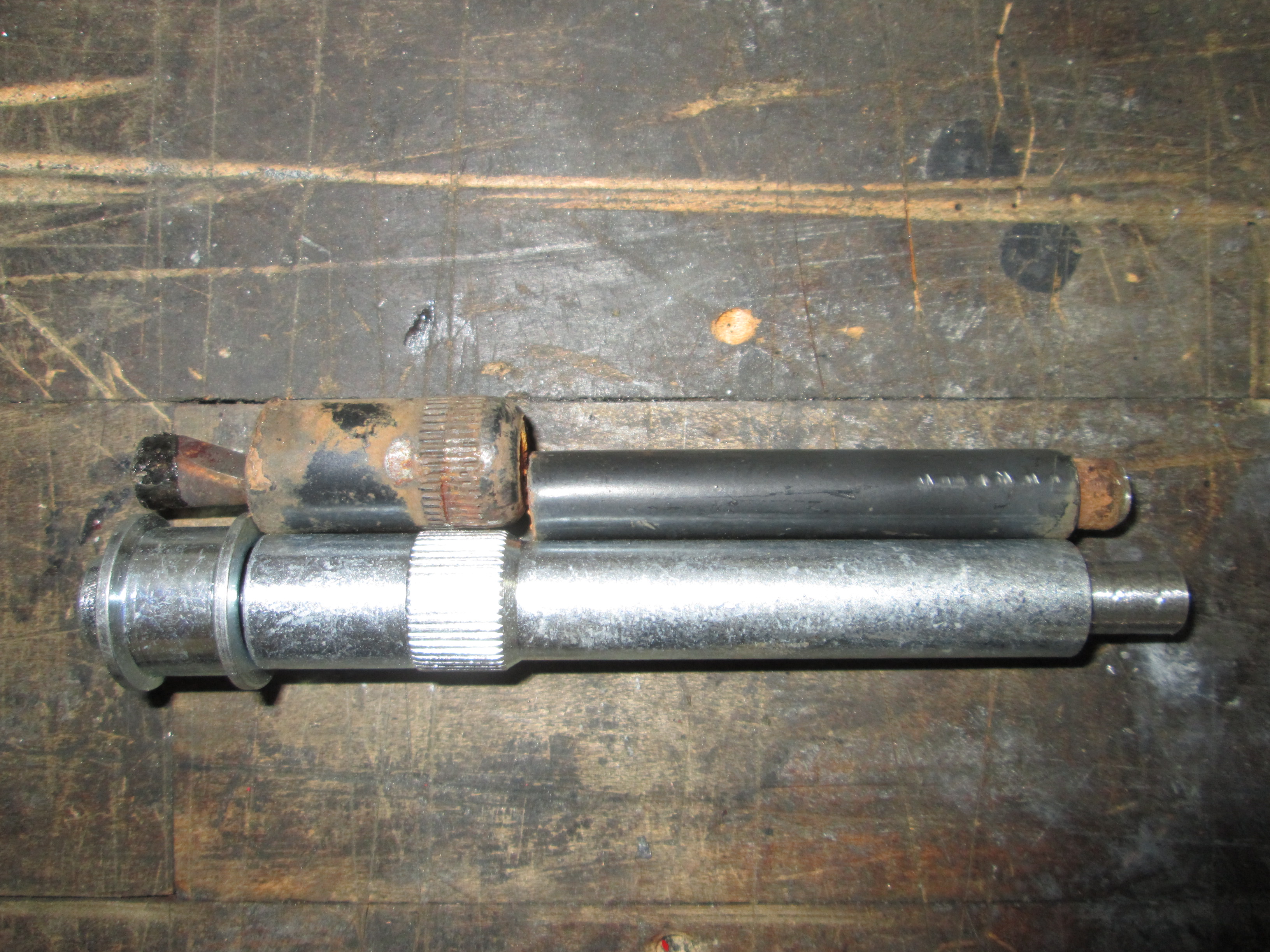
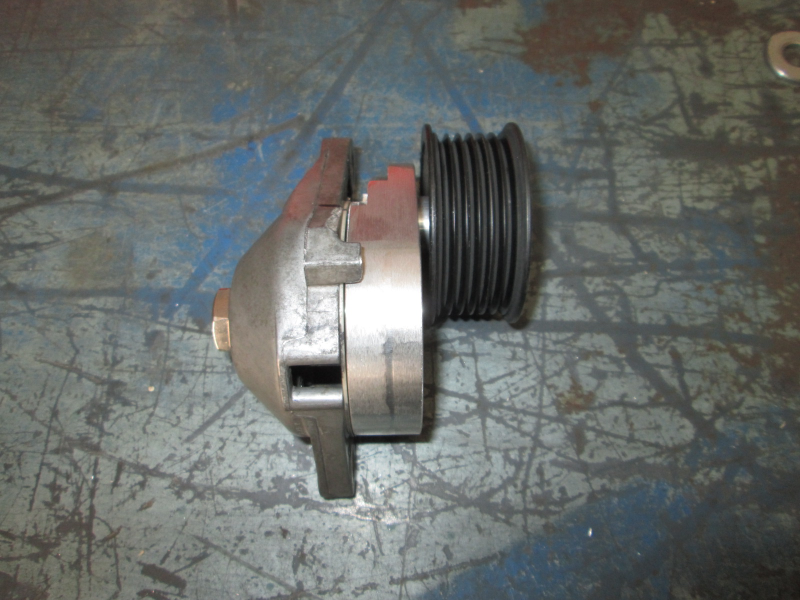
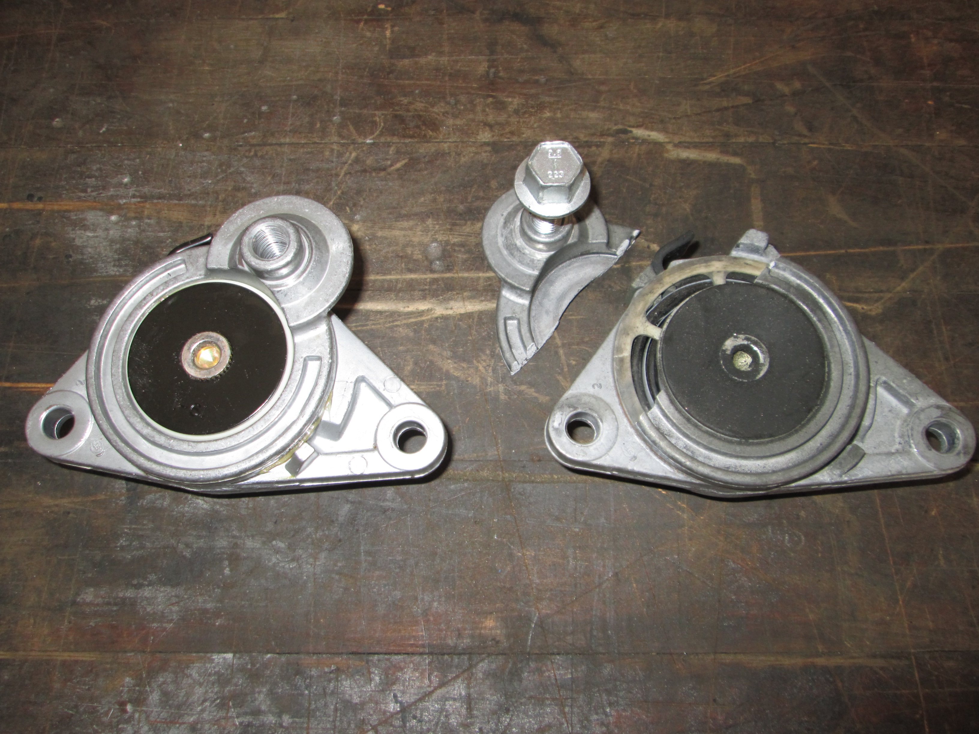
New tensioner next to OEM one:
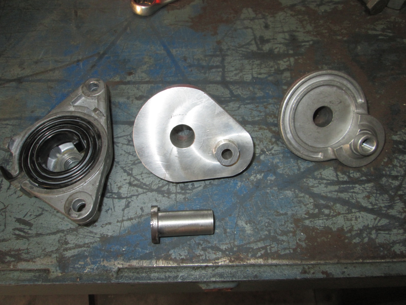
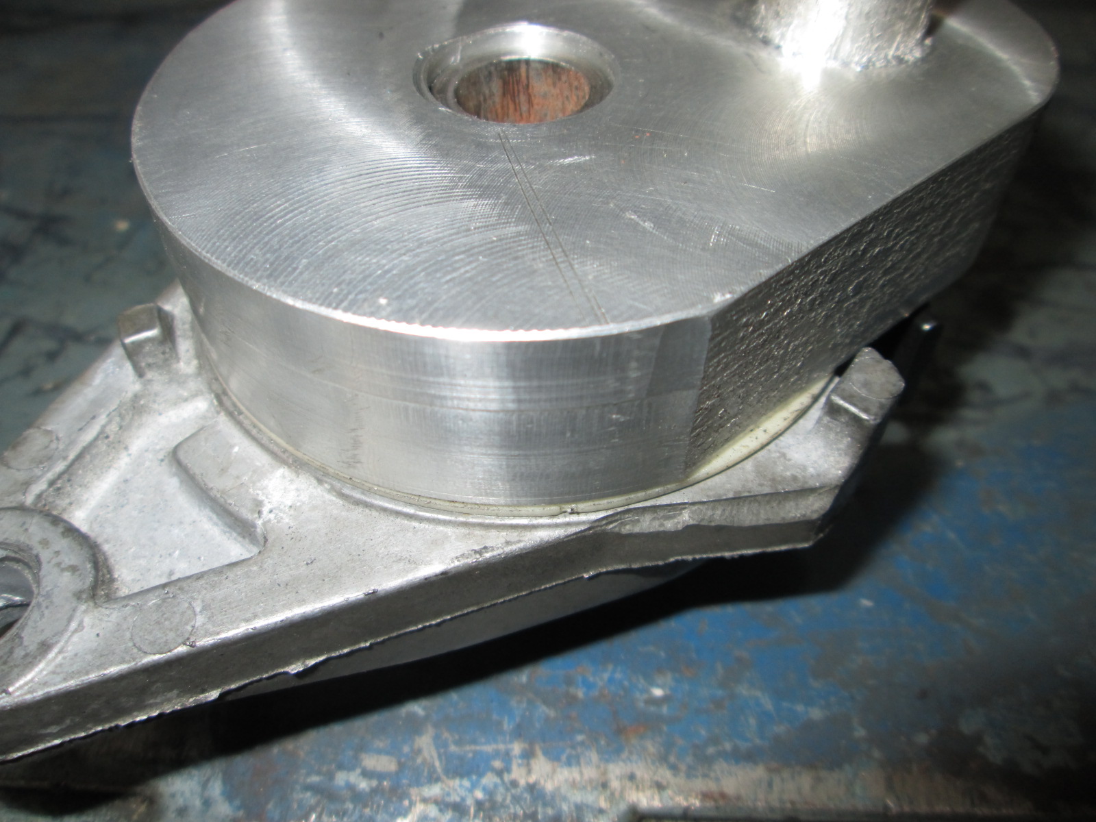
The new tensioner will be held together by a 1/2" bolt. I made a stepped steel sleeve that will be the primary support for the tensioner arm. The back of the housing has a flat area a little larger than 1" in diameter, which is what the stepped portion of the sleeve is. The backside of the housing is about 1/4" thick and I tapped it for 1/2-13, but with the limited thread engagement due to the oversized hole, will have a jam nut on the backside too. With the proper clearance between all the parts, I will be able to torque down the bolt to stabilize the sleeve, while allowing the tensioner to move freely.
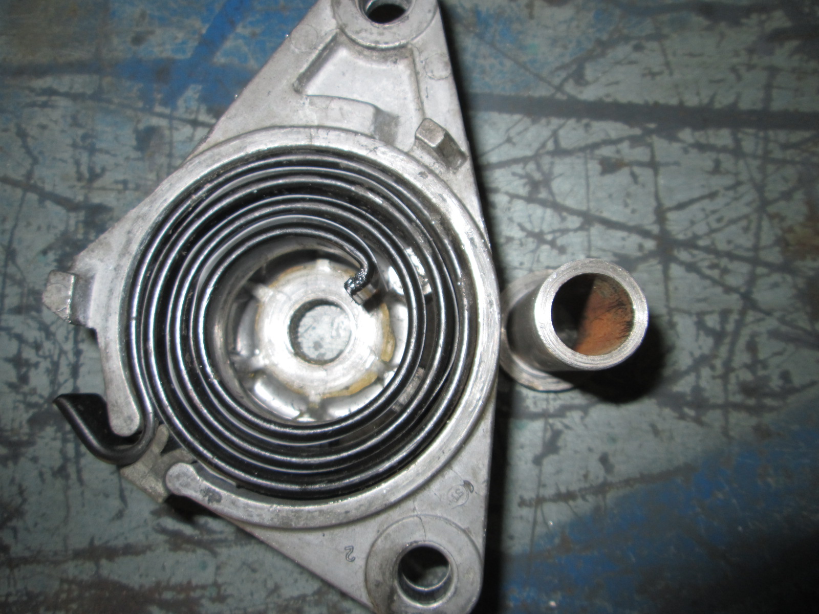

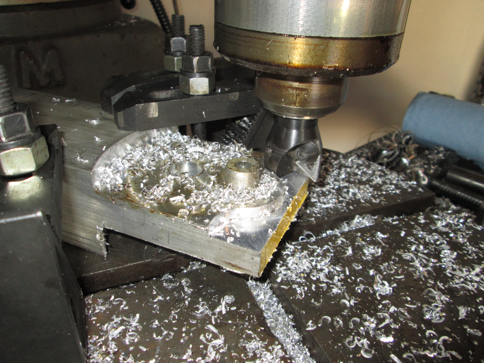
I am reusing the stock wear strip to avoid aluminum to aluminum rubbing:
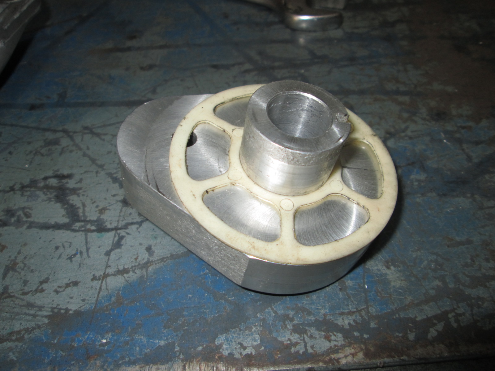
Here is a pic with the range of motion stops. I need to take the tensioner arm and set it back up in the mill and cut the clearance slots on the backside so these can be used. You can also see the steel sleeve slightly recessed below the tensioner arm surface. I need to counter bore the tensioner body so the bolt head will be flush for belt clearance, then turn down the sleeve the account for the counter bore. There will be a bronze washer at the bottom of the counter bore. The bolt with tighten the washer to the sleeve, and the sleeve the reach housing, all while keeping a few thousandths clearance between the bronze washer and the arm as well as the plastic wear strip... or at least that is the plan...
The bolt will be a stainless socket head bolt but this one is being used for mockup!

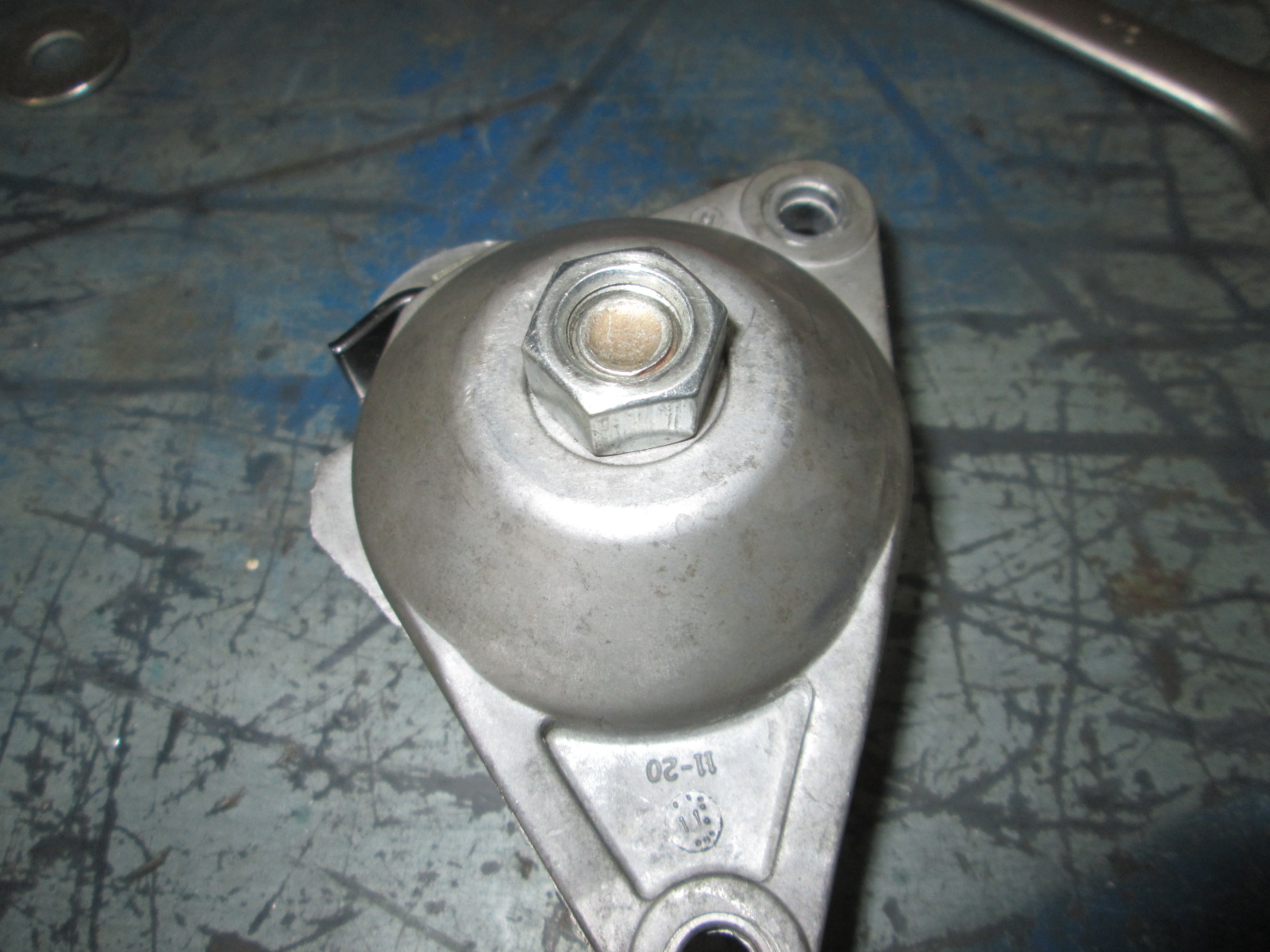
Here is a mockup nut on the backside, the final one will be stainless steel.
As you can see I need to put the sleeve in the lathe and reduce the thickness of the stepped seat to reduce this clearance.

Lots of individual setups with the mill and rotary table...
New tensioner next to OEM one:
The new tensioner will be held together by a 1/2" bolt. I made a stepped steel sleeve that will be the primary support for the tensioner arm. The back of the housing has a flat area a little larger than 1" in diameter, which is what the stepped portion of the sleeve is. The backside of the housing is about 1/4" thick and I tapped it for 1/2-13, but with the limited thread engagement due to the oversized hole, will have a jam nut on the backside too. With the proper clearance between all the parts, I will be able to torque down the bolt to stabilize the sleeve, while allowing the tensioner to move freely.
I am reusing the stock wear strip to avoid aluminum to aluminum rubbing:
Here is a pic with the range of motion stops. I need to take the tensioner arm and set it back up in the mill and cut the clearance slots on the backside so these can be used. You can also see the steel sleeve slightly recessed below the tensioner arm surface. I need to counter bore the tensioner body so the bolt head will be flush for belt clearance, then turn down the sleeve the account for the counter bore. There will be a bronze washer at the bottom of the counter bore. The bolt with tighten the washer to the sleeve, and the sleeve the reach housing, all while keeping a few thousandths clearance between the bronze washer and the arm as well as the plastic wear strip... or at least that is the plan...
The bolt will be a stainless socket head bolt but this one is being used for mockup!
Here is a mockup nut on the backside, the final one will be stainless steel.
As you can see I need to put the sleeve in the lathe and reduce the thickness of the stepped seat to reduce this clearance.
Last edited by fieroguru; 05-29-2016 at 09:04 PM.
05-30-2016, 04:12 PM
#226
Thanks!
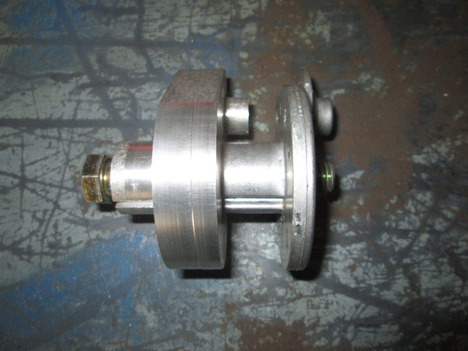
The tensioner is all done except waiting on the proper bolt. Here it is mocked up with a bolt that is about 1/4" too short. It just barely grabs the threads on the nut.

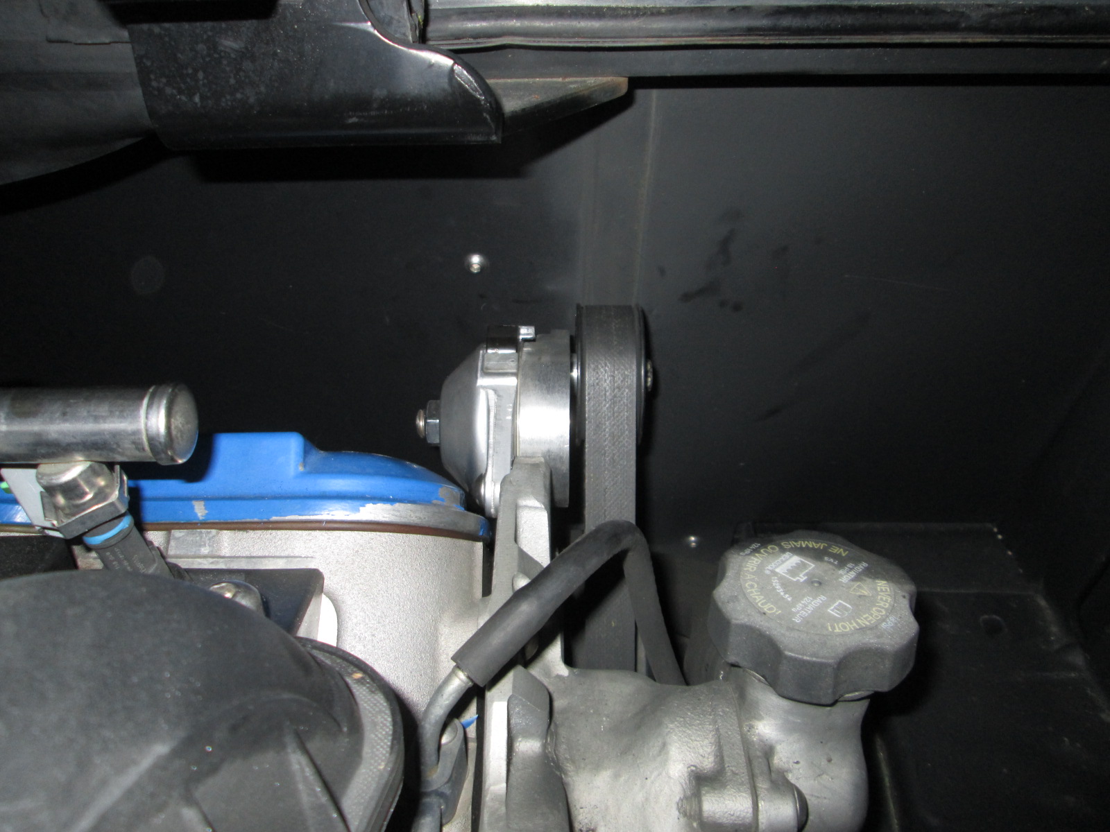
Once the longer bolt arrives, I will take the tensioner apart, reinstall the wrap spring (had it out to verify range of motion while installed), and get it installed.
The tensioner is all done except waiting on the proper bolt. Here it is mocked up with a bolt that is about 1/4" too short. It just barely grabs the threads on the nut.
Once the longer bolt arrives, I will take the tensioner apart, reinstall the wrap spring (had it out to verify range of motion while installed), and get it installed.
 06-03-2016, 04:47 AM
#230
Teching In

Join Date: May 2016
Posts: 3
Likes: 0
Received 0 Likes
on
0 Posts
I just have to say I re-read this and its so nice to see someone fabbing parts, way too many times you see people buying kits to swap anything and "if there isnt a kit that means it can't be done" type mentality.
07-13-2016, 09:43 PM
#233
Speaking of turbo builds... I have slowly started making some of the preliminary steps on mine.
I like the durability and heat shields with the factory manifolds, so for the turbo build, I have decided to use a slightly modified front LS4 manifold and a more extensively modified passenger side truck manifold.
Let's start with the LS4 one first. A little work with the cut off disk and a LOT of flapper disk work removed the factory 3 bolt setup and prepped the manifold for a v-band.
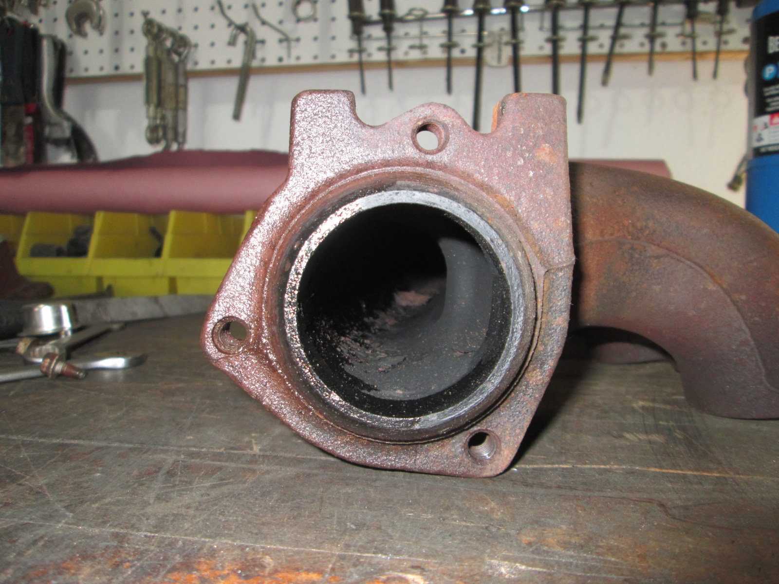
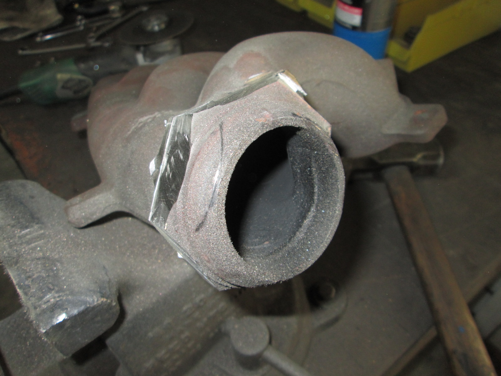

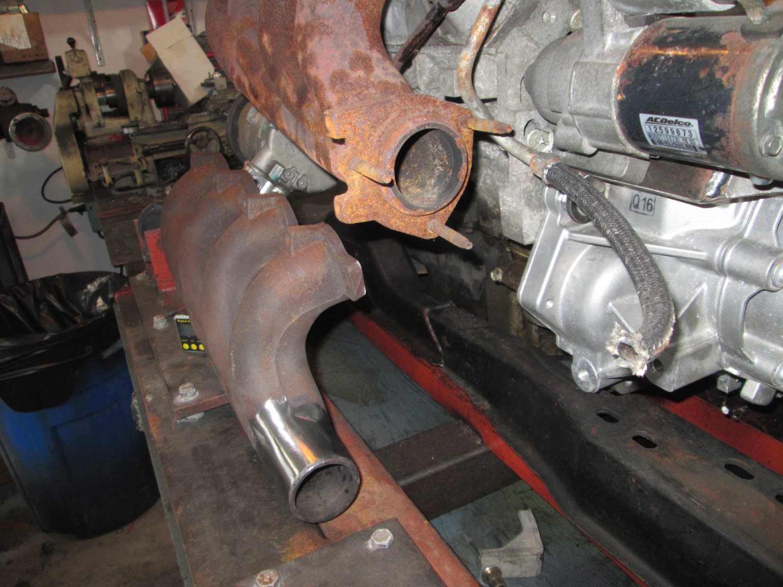
I wanted to make the truck manifold exit as close to the engine and towards the rear, so I did quite a bit of cutting and added a section of schedule 40 pipe. The pipe is too long and will likely be trimmed back to the edge of the head before attaching the v-band.


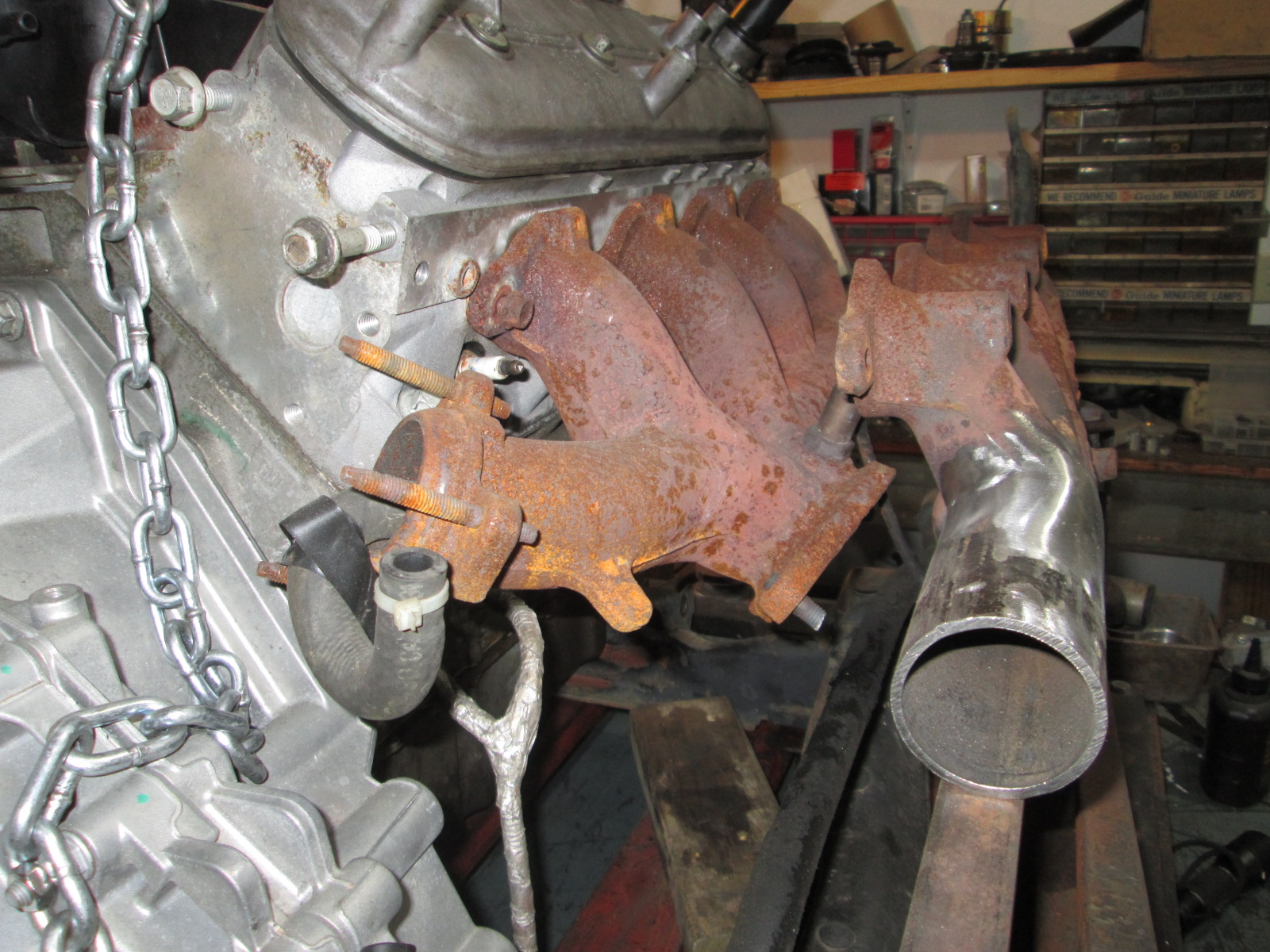
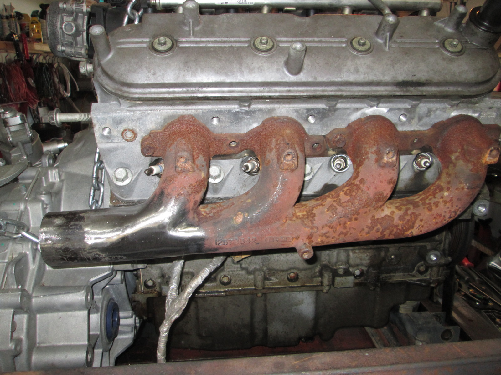
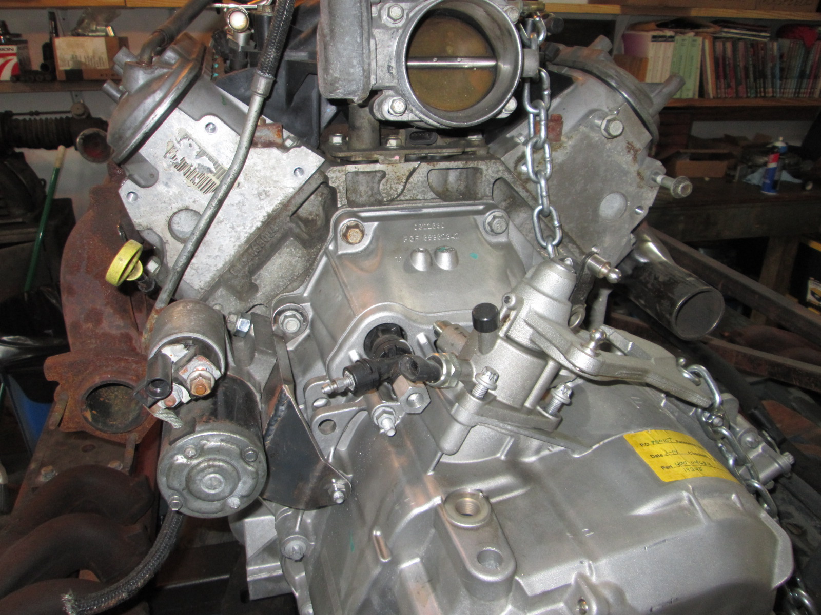
This is a mockup LS4/F40 like that in my car, here you can see the stock front LS4 manifold and the modified truck manifold. Both now dump toward the transmission area and the turbo will be somewhere over the transmission.
The v-bands should arrive in the next week and I will get them welded to the manifolds.
I like the durability and heat shields with the factory manifolds, so for the turbo build, I have decided to use a slightly modified front LS4 manifold and a more extensively modified passenger side truck manifold.
Let's start with the LS4 one first. A little work with the cut off disk and a LOT of flapper disk work removed the factory 3 bolt setup and prepped the manifold for a v-band.
I wanted to make the truck manifold exit as close to the engine and towards the rear, so I did quite a bit of cutting and added a section of schedule 40 pipe. The pipe is too long and will likely be trimmed back to the edge of the head before attaching the v-band.
This is a mockup LS4/F40 like that in my car, here you can see the stock front LS4 manifold and the modified truck manifold. Both now dump toward the transmission area and the turbo will be somewhere over the transmission.
The v-bands should arrive in the next week and I will get them welded to the manifolds.
07-14-2016, 02:00 AM
#234
Teching In
Join Date: Aug 2013
Posts: 36
Likes: 0
Received 0 Likes
on
0 Posts
Mr Fieroguru... You are the man!! It's amazing how you installed an LS into a Fiero, which is quite impressive in its own feat...and now you're moving on to make it a Turbo LS?? Awesome!!
I'm assuming there's just no room for a supercharger?? Or do you just prefer a turbo over a superchargers? Either way...you're my HERO!! Love the build, keep it up!
I'm assuming there's just no room for a supercharger?? Or do you just prefer a turbo over a superchargers? Either way...you're my HERO!! Love the build, keep it up!
07-15-2016, 11:58 AM
#235
Mr Fieroguru... You are the man!! It's amazing how you installed an LS into a Fiero, which is quite impressive in its own feat...and now you're moving on to make it a Turbo LS?? Awesome!!
I'm assuming there's just no room for a supercharger?? Or do you just prefer a turbo over a superchargers? Either way...you're my HERO!! Love the build, keep it up!
I'm assuming there's just no room for a supercharger?? Or do you just prefer a turbo over a superchargers? Either way...you're my HERO!! Love the build, keep it up!
Superchargers get quite complicated on the LS4 and in a Fiero. Clearance to the funky water pump, much shorter belt distance from face of block, supercharger drive and TB need to be on the opposite sides (and conventional ones that currently use a jack shaft would spin backwards), vertical space before interfering with the decklid supports, etc...
Additionally, the F40 6 speed has a 3.50 1st gear and a 3.55 final drive (13.38 overall launch ratio) so I don't really need excessive levels of instant off idle torque.
I have been thinking about a centrifugal blower and machining the thick flywheel to accept a serpentine belt around the perimeter and alongside the ring gear, notch the bellhousing for belt clearance, and then mount the blower over the transmission and right next to the TB... I would have to run a much larger driven pulley given the 11" OD of the flywheel, but that would help reduce belt slip as well. I still think that would be cool, but haven't found a cheap used setup to experiment with.
The turbo setup is currently in the lead simply because the flexibility with placement, more universal components, and adjust-ability depending on the activities for the day... but it will be a rather lengthy upgrade as collect the various needed parts.
 07-29-2016, 03:13 PM
#237
Teching In

Hey Guru, I hope you don't mind me asking in your thread, but seeing as you are doing a forced induction swap, you might be able to offer some suggestions.
What all can you remove from the engine bay in a Fiero. I am getting rid of most of the vacuum lines along the firewall. I am looking at the 87/88 Fuel tank purge system and trying to decide how far back I can safely remove. I removed the charcoal can years ago, when I had the High Comp, 2.9 V6. The Vacuum can is also long gone. I had left the Vent tube in place and just had it looped over by the drivers side. Now I am looking at it, along the firewall and think I am going to remove it back to the "pod?" leaving only about 6 inches to run straight up and then loop down. Obviously I need to keep the fuel tank vent, just not sure the best way to retain it with the least amount of "stuff" I prefer to keep my engine bay as free of un needed junk as possible. We have no emissions testing here, so I am I am just trying to sort out everything that I can pull off. I will add the cruise back at a later date but for now, I want it all gone.
What all can you remove from the engine bay in a Fiero. I am getting rid of most of the vacuum lines along the firewall. I am looking at the 87/88 Fuel tank purge system and trying to decide how far back I can safely remove. I removed the charcoal can years ago, when I had the High Comp, 2.9 V6. The Vacuum can is also long gone. I had left the Vent tube in place and just had it looped over by the drivers side. Now I am looking at it, along the firewall and think I am going to remove it back to the "pod?" leaving only about 6 inches to run straight up and then loop down. Obviously I need to keep the fuel tank vent, just not sure the best way to retain it with the least amount of "stuff" I prefer to keep my engine bay as free of un needed junk as possible. We have no emissions testing here, so I am I am just trying to sort out everything that I can pull off. I will add the cruise back at a later date but for now, I want it all gone.
07-30-2016, 09:55 AM
#238
How much can you remove... the short answer is "everything!" There is not a single mounting tab left on any engine bay panel and not a single thing mounted to an engine bay panel.
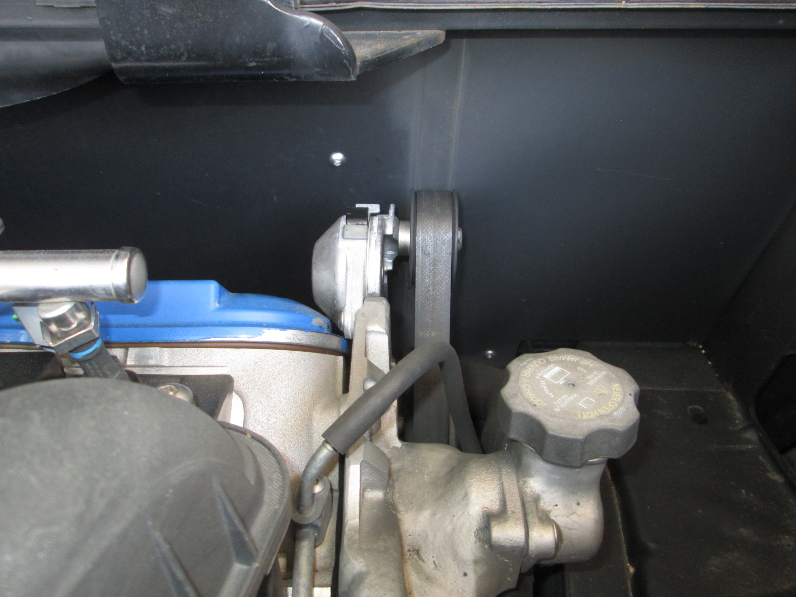
One of my tricks is to utilize the double firewall tube. On the PS I drill 1"+ access hole from the wheel well into the double firewall tube. Then I can run the tank vent tube through it into the PS wheel well and to the expansion tank. I also run the tail light harness wires through this area as well as I remove the 500 connector from the engine bay. There is also room to mount the charcoal canister in the lower wheel well area if you want to keep it, but I didn't since the LS4 doesn't have ported vacuum, only manifold.
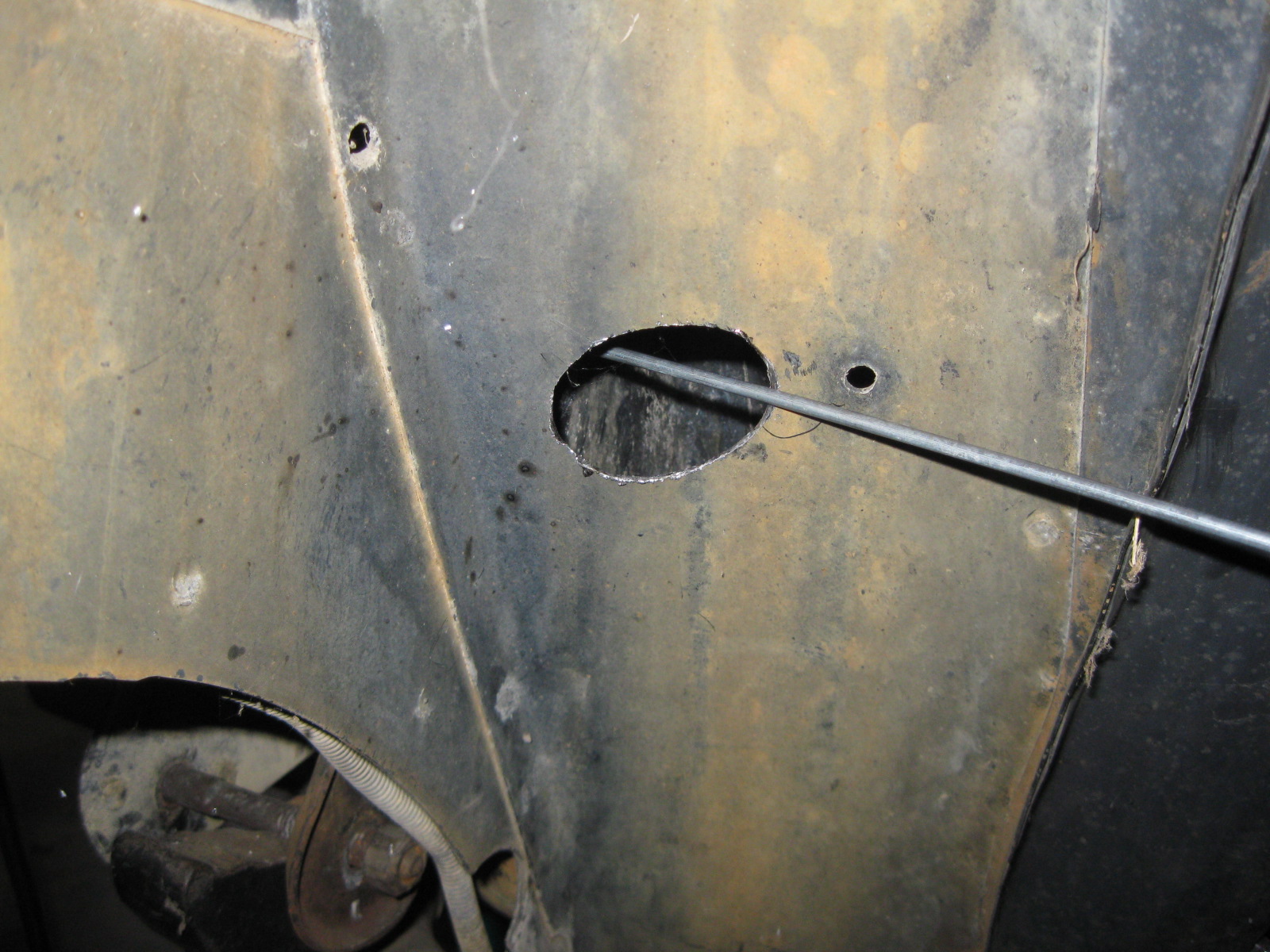
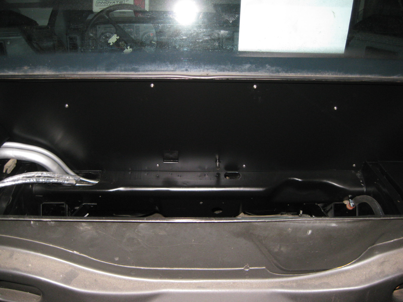
I did the same with my shift cables and ran them into the double firewall panel and have them exit from the opening of the fuel fill/vent tubes. It helps keep them away from the manifold heat. This is what my firewall looks like:
One of my tricks is to utilize the double firewall tube. On the PS I drill 1"+ access hole from the wheel well into the double firewall tube. Then I can run the tank vent tube through it into the PS wheel well and to the expansion tank. I also run the tail light harness wires through this area as well as I remove the 500 connector from the engine bay. There is also room to mount the charcoal canister in the lower wheel well area if you want to keep it, but I didn't since the LS4 doesn't have ported vacuum, only manifold.
I did the same with my shift cables and ran them into the double firewall panel and have them exit from the opening of the fuel fill/vent tubes. It helps keep them away from the manifold heat. This is what my firewall looks like:
07-30-2016, 12:15 PM
#239
Teching In
That must be custom sheet metal over the main firewall. If that's the OEM firewall you are something from the supernatural. In either case, looks awesome and something that gives me an idea to shoot for.
Do you leave the OEM fiberglass insulation in or delete it and add custom insulation. I have a gas pressure washer with up to a 3200psi tip for it, which will make quick work of the insulation if I want to remove it.
Do you leave the OEM fiberglass insulation in or delete it and add custom insulation. I have a gas pressure washer with up to a 3200psi tip for it, which will make quick work of the insulation if I want to remove it.
07-30-2016, 07:56 PM
#240
Yes, there is a fake firewall panel that is spaced about 3/8" from the OEM firewall. I don't have any engine bay insulation, just what is on the interior side of the stock firewall.
The car was built to be driven so I wanted the engine bay to be easy to clean at the car wash with the high pressure wand.
The car was built to be driven so I wanted the engine bay to be easy to clean at the car wash with the high pressure wand.