
1970 Bug Mid Engine (engine build pg15)
 05-27-2014, 02:20 PM
#61

I don't think you need to gusset the mounting tabs.
Looking at the recent suspension shots, are those at full droop? The joints at the upper spindle and especially the outer tie rod look like they are close to maxing out on angle. Be sure to use limit straps.
How will you be adjusting camber and caster?
Looking at the recent suspension shots, are those at full droop? The joints at the upper spindle and especially the outer tie rod look like they are close to maxing out on angle. Be sure to use limit straps.
How will you be adjusting camber and caster?
 05-27-2014, 02:23 PM
#62

So I got little bit done over the weekend. I was on dog sitting duty and I didn't have a ton of time. 4 dogs for 4 days is a pain! They like to "help" me work on the bug. More like get in the way, but if dogs could talk, they would disagree.
Before
After
The future

Before

After

The future
05-27-2014, 02:36 PM
#63
I don't think you need to gusset the mounting tabs.
Looking at the recent suspension shots, are those at full droop? The joints at the upper spindle and especially the outer tie rod look like they are close to maxing out on angle. Be sure to use limit straps.
How will you be adjusting camber and caster?
Looking at the recent suspension shots, are those at full droop? The joints at the upper spindle and especially the outer tie rod look like they are close to maxing out on angle. Be sure to use limit straps.
How will you be adjusting camber and caster?
Camber is done either on the top or bottom arm at the spindle side with the 3/4" heim. It does suck that I have to pull the bolt out to turn the heim, but for the once a year I will do it, I can live. Caster can be adjusted on the top arm with the inner heims. I have it set to about 5 degrees right now. We will see how it feels when I get to drive it.
05-27-2014, 04:58 PM
#64
 05-27-2014, 05:21 PM
#65
TECH Fanatic
I agree with TheBandit, this thing is so light and as long as the travel is free and smooth gussets are not necessary.
By the way nice workbench top (with the gussets) I tried to do my dash mockup on the granite kitchen counters until wife saw the plan.
By the way nice workbench top (with the gussets) I tried to do my dash mockup on the granite kitchen counters until wife saw the plan.
05-27-2014, 05:59 PM
#66
Adjustments could be a real pain with that setup, but how often you need/want to adjust will depend a lot on how you use it. If you are switching around from street to short course to long course on a regular basis, you may want a quicker means of adjusting. I doubt you want to revisit it this late in the game, but you could consider replacing your welded tabs at the top with mounting plates and brackets that can be shimmed for camber & caster adjustment. You could then still use your rod ends for gross/initial adjustment and have some shim stacks pre-setup for adjusting at the track. For caster adjustment only you can put separation between your mounting tabs then use shims to shift the arms forward or rearward. There are a lot of ways to do it, but of course you can certainly run what you made - nothing wrong with that at all!
Something else I noticed about your lower arms is you are using a rod end with the shaft in bending (due to the load of the spring). A friend on another forum was recently talking about how this is bad practice and likely will result in a rod end failure. This friend is an engineer whose day job is suspension modelling for race teams and I trust his experience. I will forward this thread on to him and see what he has to say about your particular design and what he might recommend you do to improve it, if necessary. I have a feeling he would favor a weld-in joint, for example like what is used here: http://www.kartek.com/Media/Images/Large/86500R.jpg
Something else I noticed about your lower arms is you are using a rod end with the shaft in bending (due to the load of the spring). A friend on another forum was recently talking about how this is bad practice and likely will result in a rod end failure. This friend is an engineer whose day job is suspension modelling for race teams and I trust his experience. I will forward this thread on to him and see what he has to say about your particular design and what he might recommend you do to improve it, if necessary. I have a feeling he would favor a weld-in joint, for example like what is used here: http://www.kartek.com/Media/Images/Large/86500R.jpg
05-27-2014, 07:38 PM
#67
Bandit -
Yes I agree with you. Making adjustments is not going to be a quick ordeal. It will be a pain. I do like your ideas and if it turn out to be too big of a pain, it will change. I don't see myself taking it to more then 5 big track events a year and maybe 10 auto X event. I will just used my DD alignment for small events and change things up on high speed, larger tracks. This isn't going to be my DD, unless its too much fun, so I am not worried about having a more track friendly alignment and driving it on the streets. I don't see my tires lasting too long anyways...
As for the bottom arm mount, I could do the uniball setup like you mentioned. But, I don't see much of a benefit going that route. It is pretty much a heim but with a stronger outside. I didn't cheap out on the heims I got either. I am trying to somewhat model the suspension and mounting points off of some of the desert rails we have here. Most of the medium size cars (2800-3600lbs) have 3/4" heims mounted the same way I do. The bigger cars step up to a 7/8" heim. Now I agree that it will wear out faster then it should but my car will be half the weight and have a quarter of the abuse as those cars. I was also thinking of mounting the heim rotated 90 degree, but that would limit my steering badly.
There is going to be a lot of trial and error. That is what I planned on. GM has a whole crew of people working on making sure stuff like this works out. I have myself and other peoples input and thoughts. I don't mind trying something and having it break or not work right. It is part of learning new things! I just need to get this thing running so I can start the real road and track test!
 05-29-2014, 10:41 AM
#69
As for the bottom arm mount, I could do the uniball setup like you mentioned. But, I don't see much of a benefit going that route. It is pretty much a heim but with a stronger outside. I didn't cheap out on the heims I got either. I am trying to somewhat model the suspension and mounting points off of some of the desert rails we have here. Most of the medium size cars (2800-3600lbs) have 3/4" heims mounted the same way I do. The bigger cars step up to a 7/8" heim. Now I agree that it will wear out faster then it should but my car will be half the weight and have a quarter of the abuse as those cars. I was also thinking of mounting the heim rotated 90 degree, but that would limit my steering badly.
I am not saying it wont work as you built it or that it is going to fail the first time you hit a bump in the road, but I understand it is not best practice so I wanted to point it out for you to consider.
Here's a pretty cool thing to read through. You might also like their arm design from the perspective of adjustment. http://www.kineticvehicles.com/WArmTests.html
Last edited by -TheBandit-; 05-29-2014 at 11:01 AM.
05-29-2014, 01:34 PM
#70
That is a good article! I am surprised that the heim bent before the arm. The good new is that guy was using thinner arm tubing and a smaller heim then me. Not sure what heims they were either. Could have been the cheap China ones. I was looking to do an arm design like the one he did, but I can't. At least not on the lower arm. The coilover has to mount in the middle of my arm and needs a brace going across. I am limited on space to be able to mount it on the top arm. Yes my heim is threaded out quite far at the moment. I am going to suck it in about a 1/2" so my tires don't rub the fenders if I am turning and hit a bump. I also need to add the jam nut. So it looks like there won't be much thread showing after all my final adjustments.
05-29-2014, 01:39 PM
#71
Keep in mind he was testing to failure, intentionally. It didn't fail during use - he wanted to see if the arm was going to fail and instead found the rod end shaft to be the failure point. I would expect your arm to fail in the same way under severe loading, which is why you might consider going with a uniball type end instead. It may still be plenty strong as is, but it could be more betterer 
If it were mine, I would thread that sucker all the way in as far as it will go and either live with whatever track width you get or make a longer arm that incorporates a uniball. Then use the upper arm for adjustments.
If it were mine, I would thread that sucker all the way in as far as it will go and either live with whatever track width you get or make a longer arm that incorporates a uniball. Then use the upper arm for adjustments.
05-29-2014, 02:11 PM
#72
Does anyone have some knowledge of aerodynamics? I am not looking to lower the drag coefficient but need to know where I should put my air ducts. I have found some wind tunnel test but none of them show the side of the car. The Bug will be getting a small spoiler at the top of the rear window to help break the rear airflow up to help make a nice low pressure zone at the rear. I am looking to use that low pressure zone to vent most of the air out of the engine compartment. So I have two ideas of where the inlet ducts are going to be. First thought was the rear of the rear side windows. I would cut the glass and put some ducts in place of the section of glass that was removed. I am just not sure if that is going to be an area where it is a high pressure zone like I need. My second thought was a duct under the car. The whole bottom of the car is flat. The duct would stick 1 inch or so below the bottom of the car. I was thinking it would work how a jet boat works. Sucks from the bottom and blows out the trunk lid into the low pressure zone.
Any other ideas?
Any other ideas?
05-29-2014, 02:44 PM
#73
Have you considered finding room up front? Like this:

More info here: http://www.rx7club.com/old-school-ot...vw-bug-906636/
Here's another implementation: http://www.shoptalkforums.com/viewto...?f=19&t=129766
More info here: http://www.rx7club.com/old-school-ot...vw-bug-906636/
Here's another implementation: http://www.shoptalkforums.com/viewto...?f=19&t=129766
05-29-2014, 04:04 PM
#74
Yes that was the original plan. Not going to happen though. I can't bring myself to mounting it up front.
A - don't want hot tubes in the car
B - not going to run the tubes under the car
C - I am not cutting holes in any of the body panels
D - not much room with how I built the frame
E - I would have to mount my heat exchanger up there as well and there is no way the piping will fit
So....I am stuck having to make an air induction system to cool everything out back. Yes I am stubborn
05-29-2014, 05:20 PM
#75
Yes you are being stubborn! I am stubborn too so here goes...
Most mid/rear engine cars still have front mounted radiators for a good reason! It is tough to get airflow out back. Here are some examples: Bugatti, Porsche, Audi R8, Ferrari.
I would consider raising the tunnel section and running your cooling lines along that route, something like this:

The intercooler would still need to be fed somehow, but I think that is a lot less critical than engine cooling. If you are seriously stuck on rear-mounting things, there is always this classic option:

Most mid/rear engine cars still have front mounted radiators for a good reason! It is tough to get airflow out back. Here are some examples: Bugatti, Porsche, Audi R8, Ferrari.
I would consider raising the tunnel section and running your cooling lines along that route, something like this:
The intercooler would still need to be fed somehow, but I think that is a lot less critical than engine cooling. If you are seriously stuck on rear-mounting things, there is always this classic option:
Last edited by -TheBandit-; 05-29-2014 at 05:38 PM.
05-30-2014, 11:31 AM
#77
Heck yeah!
Here is a decently executed front radiator. I think you could make the cutout in the front facia a little less noticeable by just having a single or two wide openings rather than a grill-like set of slots. http://www.gerrelt.nl/modifications-...tradiator.html
Here is a decently executed front radiator. I think you could make the cutout in the front facia a little less noticeable by just having a single or two wide openings rather than a grill-like set of slots. http://www.gerrelt.nl/modifications-...tradiator.html
05-30-2014, 04:19 PM
#78
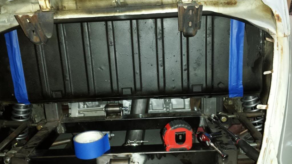
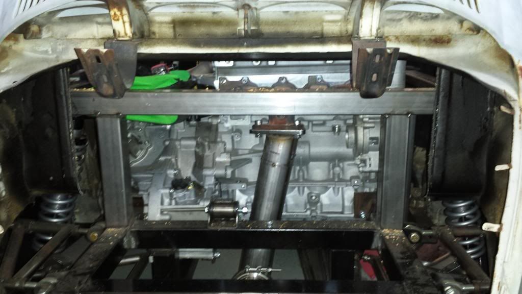
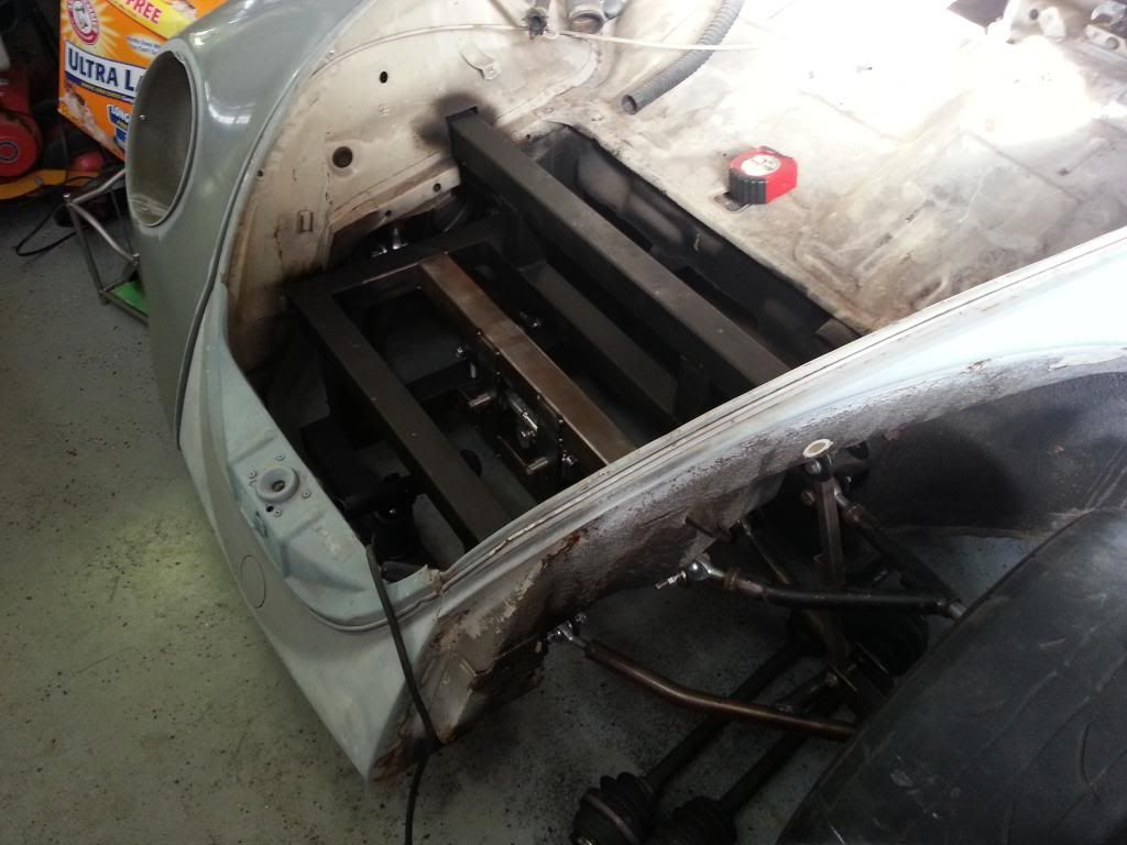
So you got me to think a little, very little, about a front radiator. If I make a front splitter, paint the center of the body black, cut a hole out of the nose and cover it in black mesh, it might pass my stubbornness. But I am still left with running hot tubes in the car. I can't raise the tunnel and can't run them below the frame. I might be able to squeak them down the center of the car but the shifter might get in the way. I am very limited on room inside the car. This would still force me to keep the intercooler in the back as well. There is no way that two 2.5" tubes are going to go from front to back of the car. Refer back to this picture to see my problems. The two middle bars are 14" apart
 [/URL]
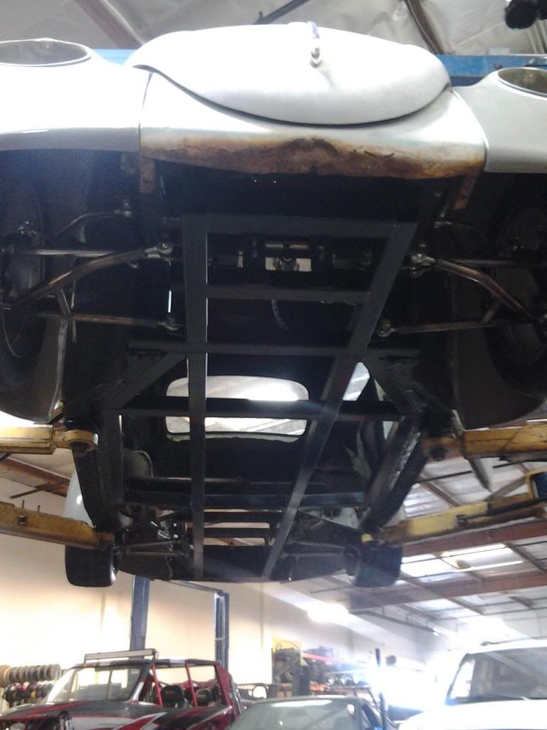
This is an old picture with less bracing then now but you can see there is a little room to put a radiator, just not a very big one.
 [/URL]
[/URL]This is an old picture with less bracing then now but you can see there is a little room to put a radiator, just not a very big one.
[/URL]
05-30-2014, 05:01 PM
#79
You may have missed the opportunity to really plan this in for integrated front mount, but I would spend some time in the garage with a piece of hose or something to start mocking up possible routes. You might come up with something. For example it looks like you might have room if you run it on the inside of the outside frame rails rather than down the center. If you need to pass through frame rails, you can cut a hole and put weld a cross tube into the frame. Alternatively I have seen people use the actual frame rails as coolant lines, but you would have had to do that from the start.
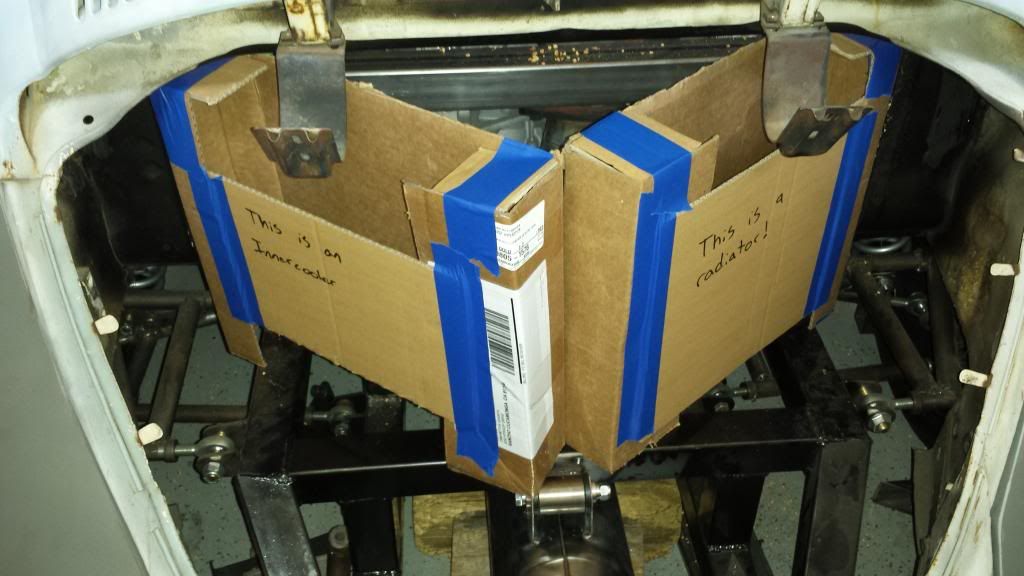
The rear mount isn't the end of the world, it's just going to suck if it doesn't work out. Assuming you go rear mount, I would try to get a full-width radiator and put the currently-sized intercooler in front of a portion of it. The size of your cardboard mockups does not look great and you are going to need as much cooling area as you can get with limited airflow You will also want to have two strong puller fans, ducting sourcing air from under the car, with an exit in a LP zone, potentially the factory vent on the factory engine bonnet.
I wish I could see it in person. There may be some other interesting options. I am still a huge fan of front mount. It's better for cooling and better for weight distribution too, plus it will give you some needed room out back for exhaust, turbo, etc.
I don't envy the packaging challenge you have!
05-30-2014, 08:51 PM
#80

I had a similar issue to deal with on my 914 Porsche/LS1. I mounted the radiator in the front with a grill opening in the bumper. The exit air is through a hood diffuser. The lines are steel tube, 1 1/4" that follow recessed channels in the pan under the car.
Your thought of running two 2.5" lines is overkill. There are may 914/V8 conversions that run 1 1/4" (actually 1" hot side, and 1 1/4" cold side) lines successfully. They traditionally (unlike mine) vent the exit air into the front wheel wells.
Anyway, 1 1/4' should greatly simplify your problem. Would there perhaps be enough room under the Bug running boards on each side to route the lines?
Andy1