

Turbo 6.0 T56 build
 03-20-2017, 12:46 PM
#1


This is my in progress build.
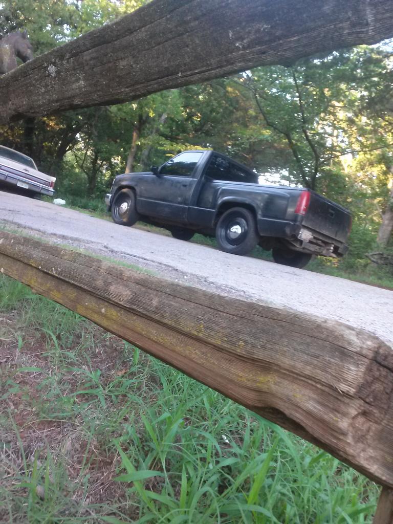
The victim is a 1990 Chevrolet Silverado.
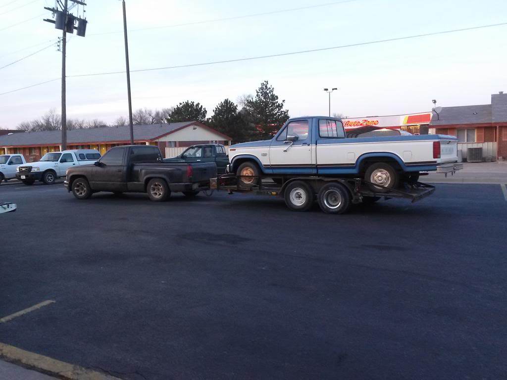
Dragging an F150 about 130 miles.
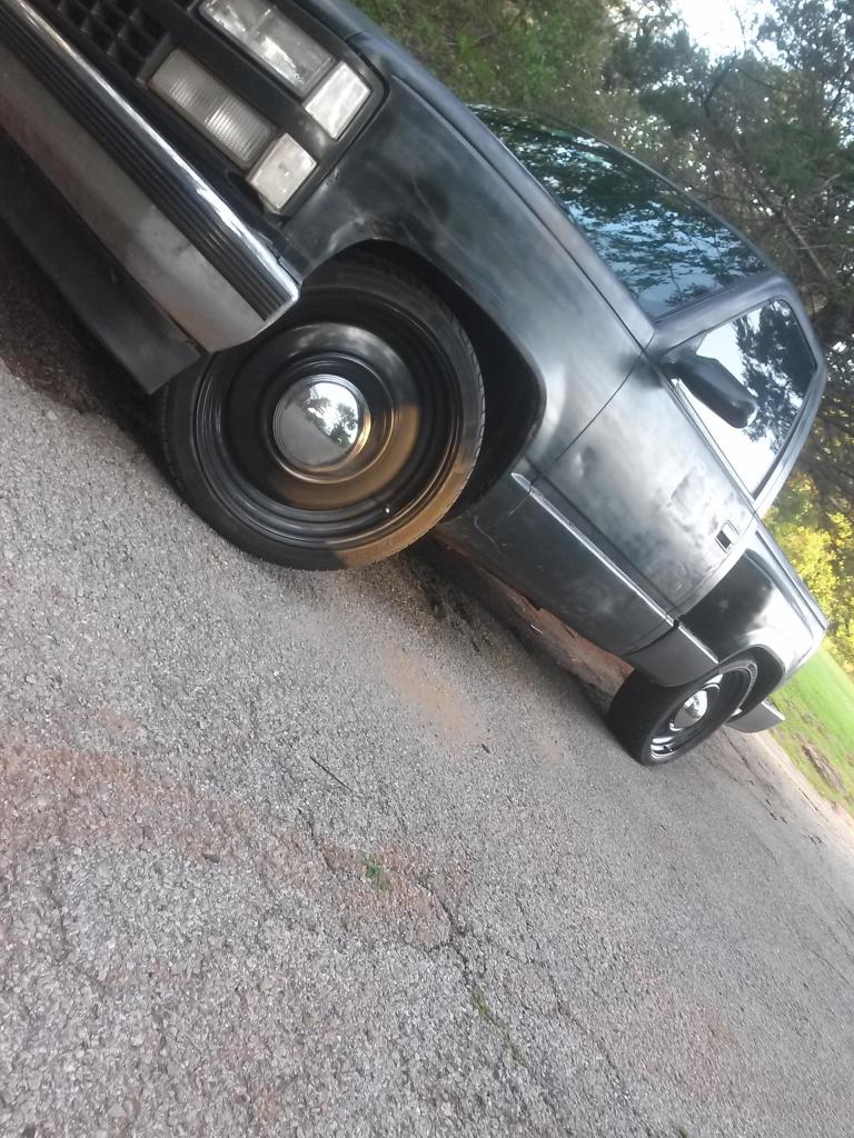
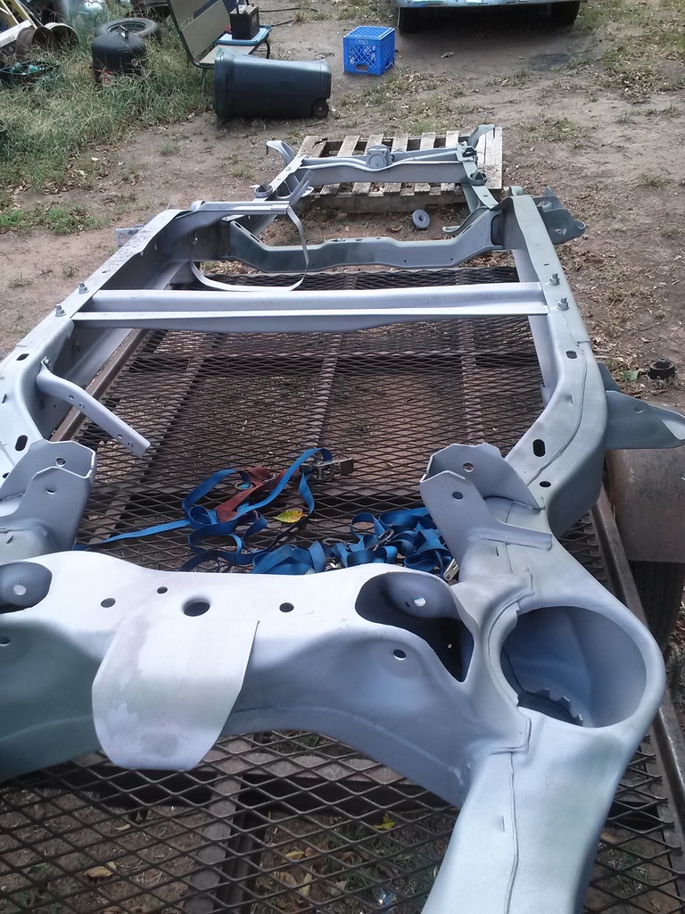
The pics below show the transport wheels with some moons I just set on to see how they might look.
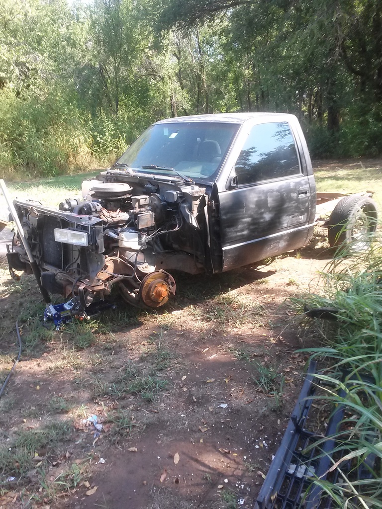
Starting to tear apart the truck.
Bare frame back from blaster
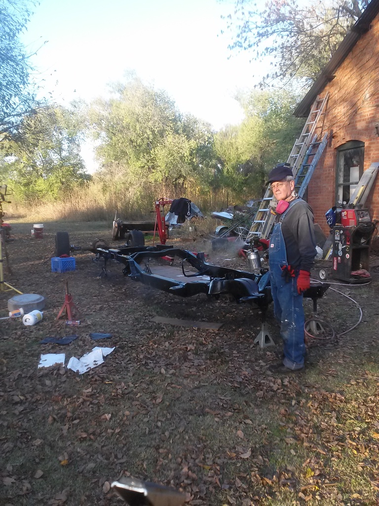
My dad and I painted the frame with rustoleum on a still day.
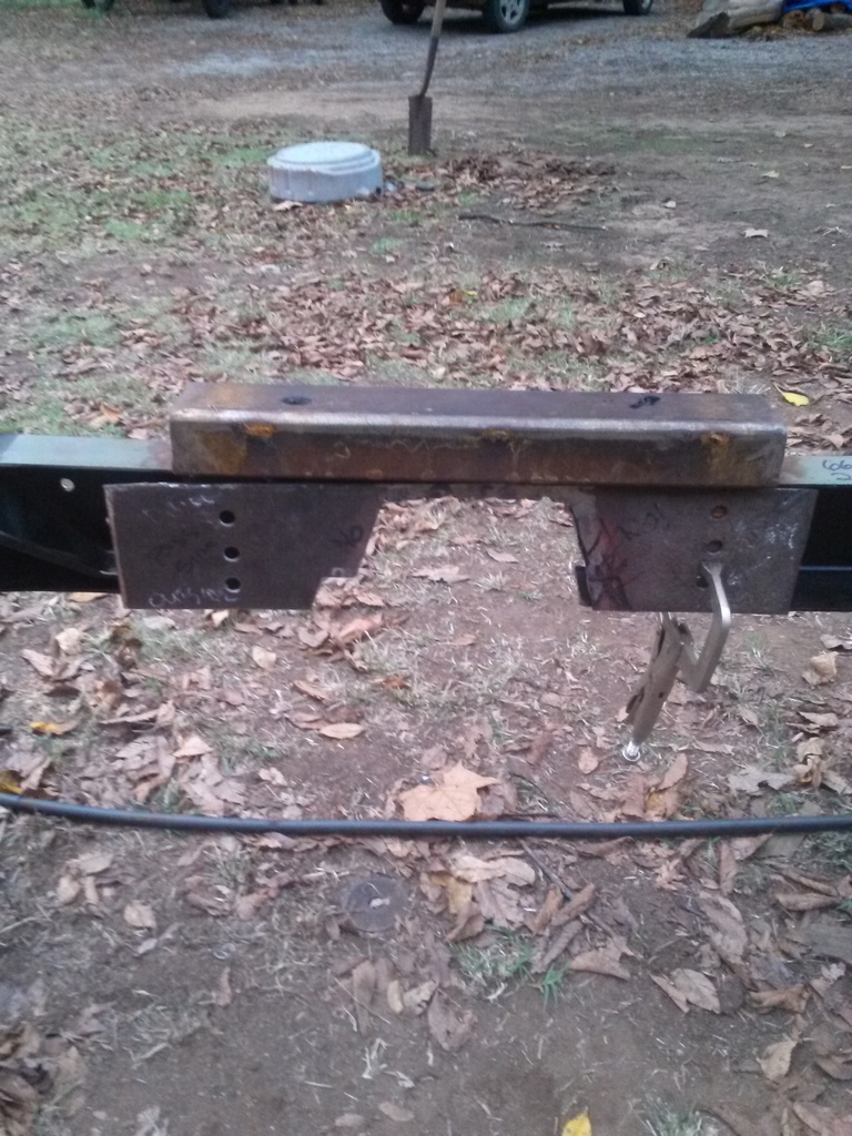
Frame before C notch cutting. You Can see the reinforcement I added to brace the frame for the cutting
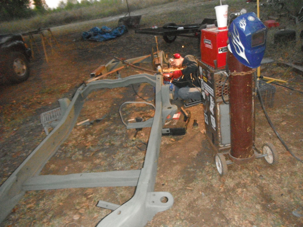
Working on the C notch
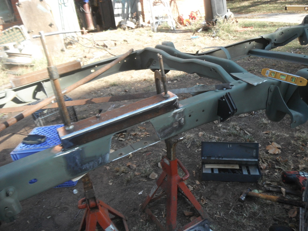
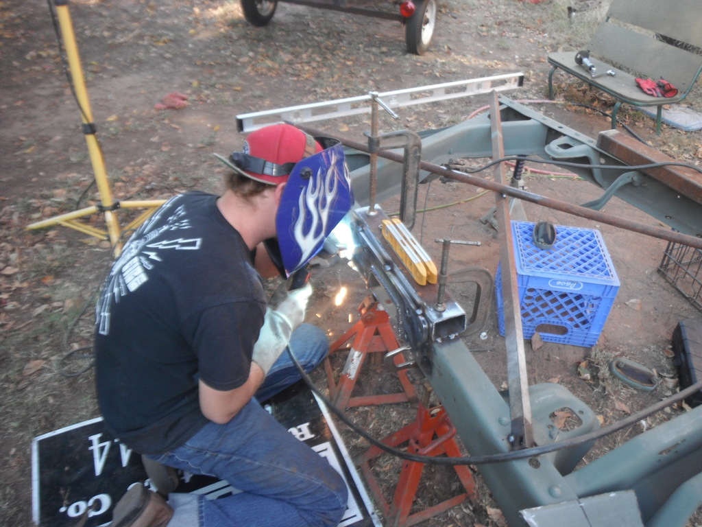
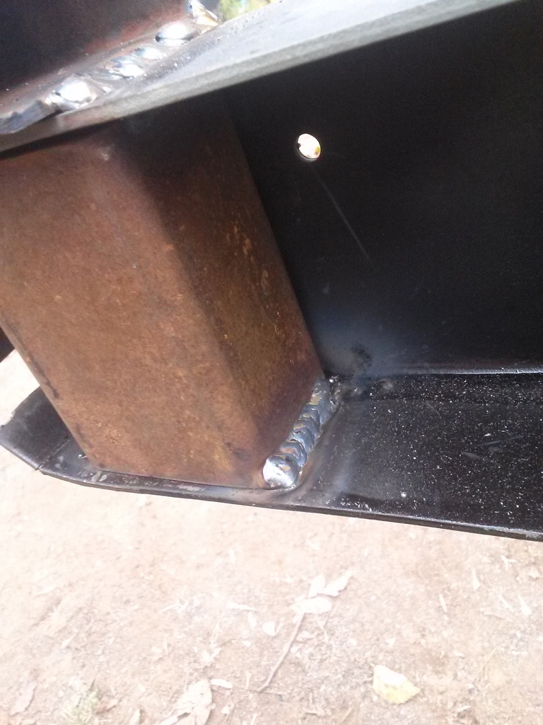
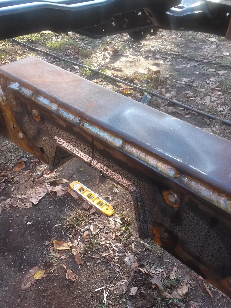
When I was mocking up the c notch I decided to go ahead and build it as high as possible since I was welding it in anyways. So the c notch itself is fully welded, the frame is reinforced with uprights immediately in front of and behind cut and a horizontal reinforcement laid across the cut on the TOP side of the frame. Finally, I boxed in the frame with plate steel.
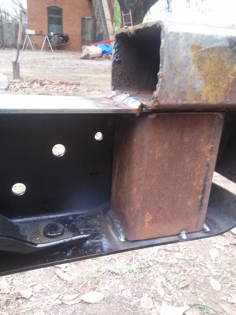
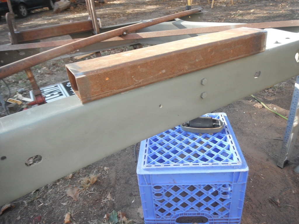
This picture shows the upright welded in front of the c notch cut. Also, you can see the horizontal member a piece of 2x3 square tube laid over the top of the frame which extends approximately 3 to 4 inches beyond the cut.
Another shot of one of the uprights
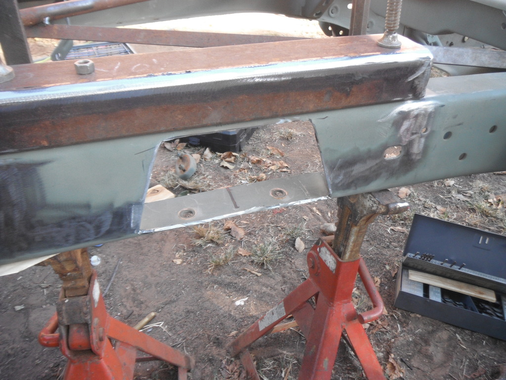
C notch is fully welded
Starting to box in the frame on the inside for further reinforcement. Also visible are the holes where I rosette welded the inside reinforcement plate to the uprights
Below are some pics that show the finised c notch.
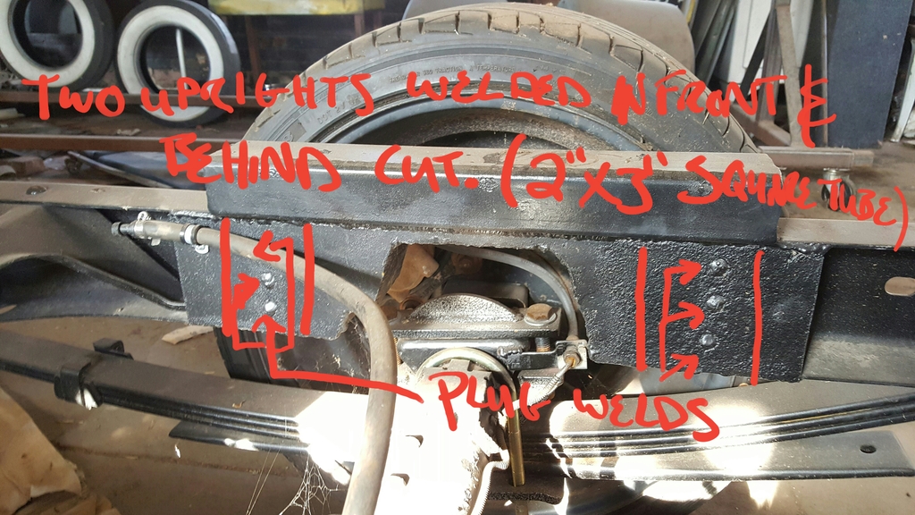
I made this rough drawing real quick for someone who inquired about the way I built this notch


------------------------------
On to the suspension…. Time to remove all the old bushings to replace them with poly.
 .
.
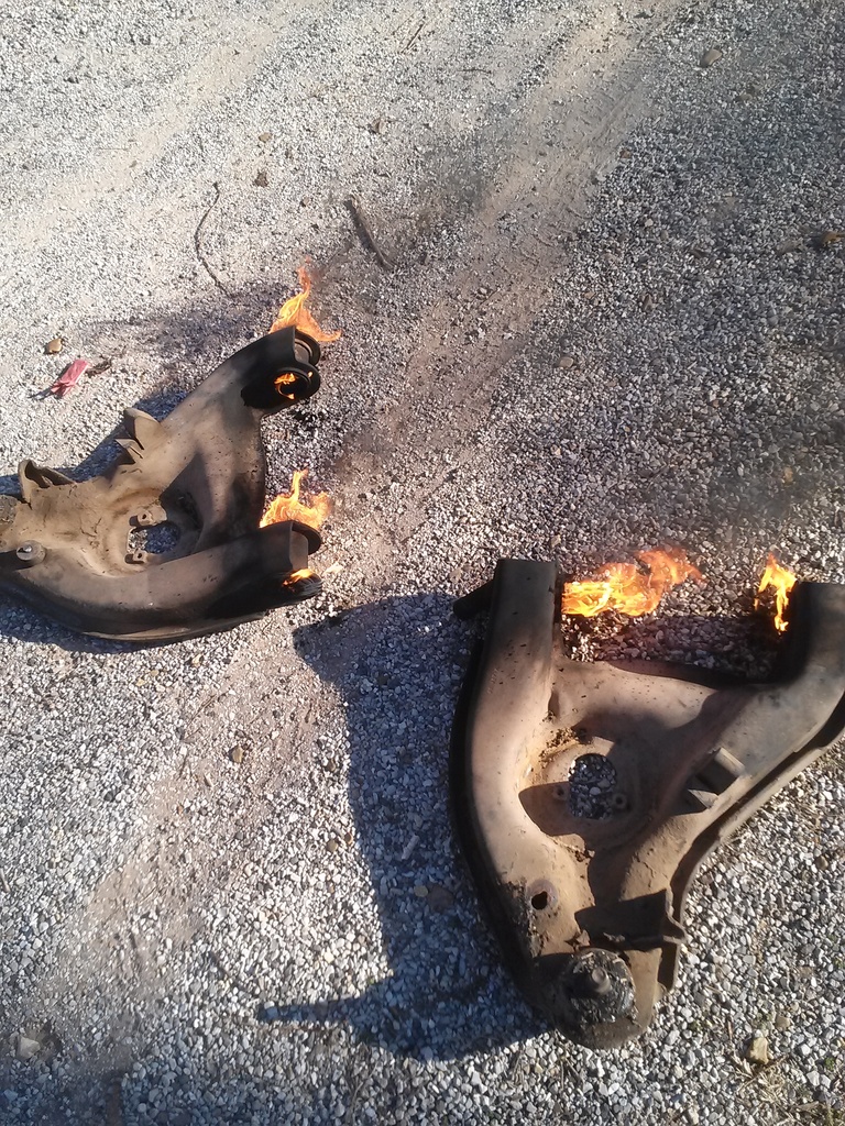
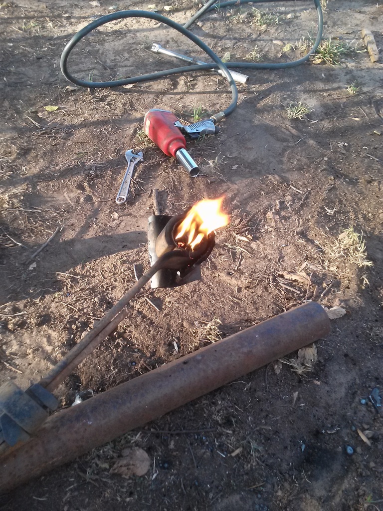
I found the easiest way to remove the OEM rubber bushings was to just light them on fire with the torch
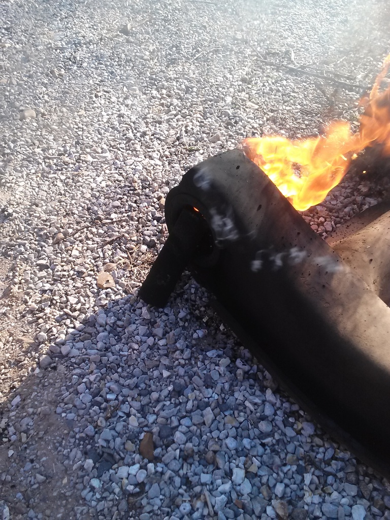
The inner metal sleeves will actually start to slide out and in some cases will actually “shoot” out a few inches.
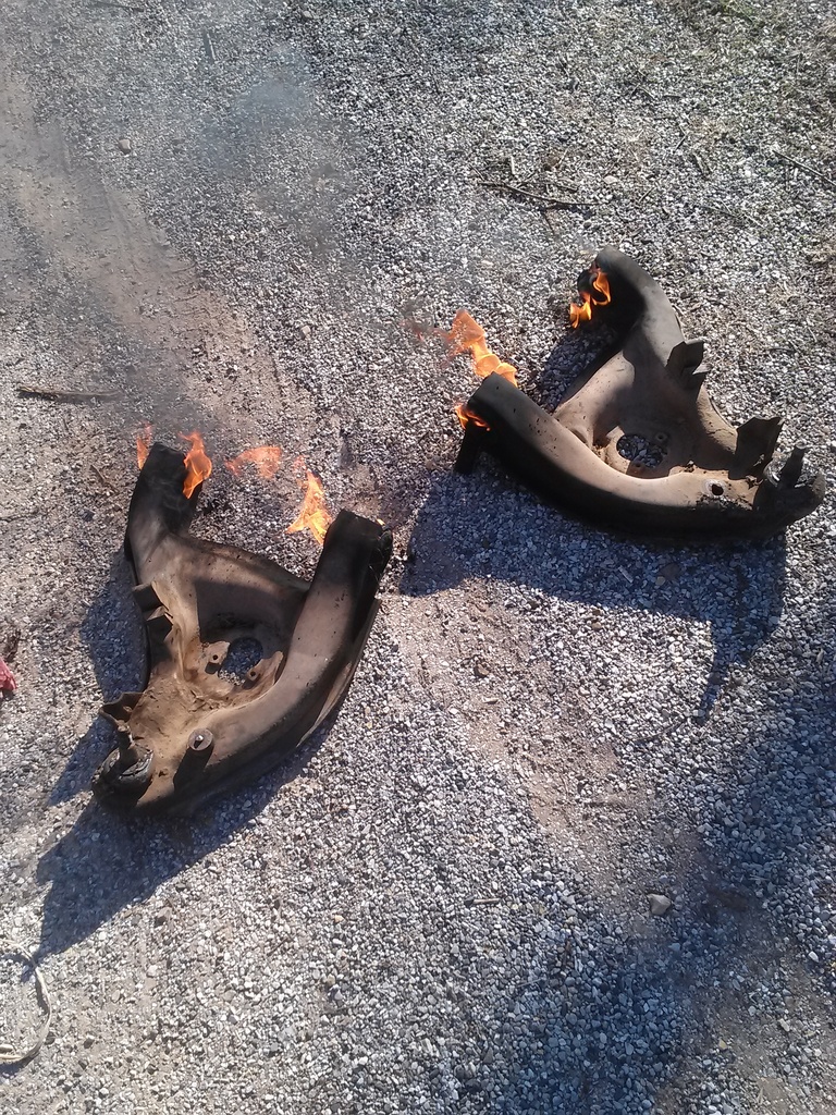
Both control arms with bushings burning
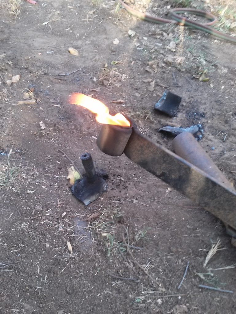
Removing the leaf spring bushings
Once the majority of the OEM rubber bushing is gone, you can grab a screwdriver, scrape out the last little bit, maybe stuff some rags through it with some solvent. Somewhat visible in this picture is the metal sleeve inside the spring eye. Using the poly bushings I had required removing this inner metal sleeve. An impact hammer, chisels and a cutoff wheel made relatively easy work of it.
I had to machine some spacers or sleeves to make the bushings fit the shackles as they were too small for some odd reason.
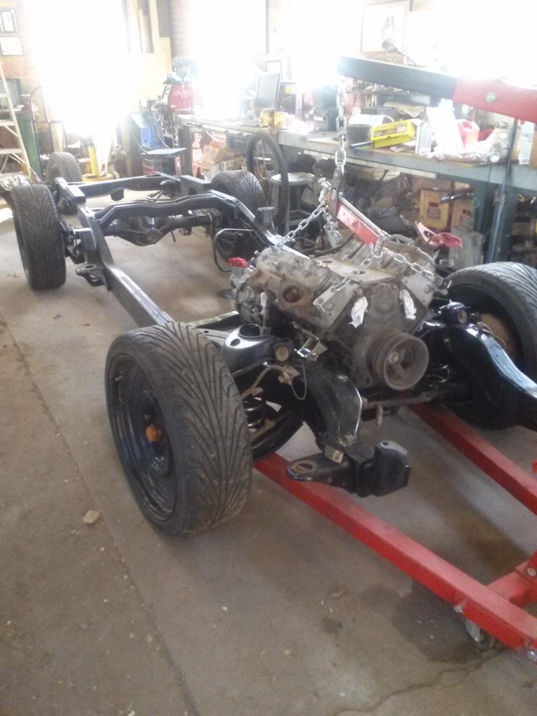
One of the first dry fits for the LQ4 in the frame. Interesting factoid, I was planning on using polyurethane engine mounts but…… I had forgotten the fact that you have to drop the lower control arms to back up the nuts that hold the rubber/poly mounts to the frame. All this just to change engine mounts, plus I had quite a bit of fun stuffing all four control arms back into the frame with the poly bushings.
Not wanting to deal with that again, plus the fact that racetruck ……. “Solid mounts it is” I said outloud.
Squaring everything up in the frame:
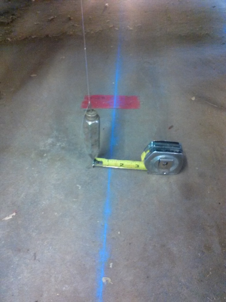
I established a centerline for a point of reference to begin measuring.
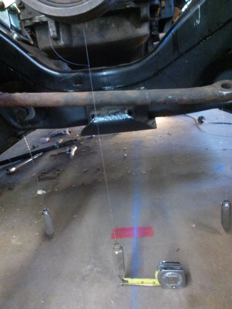
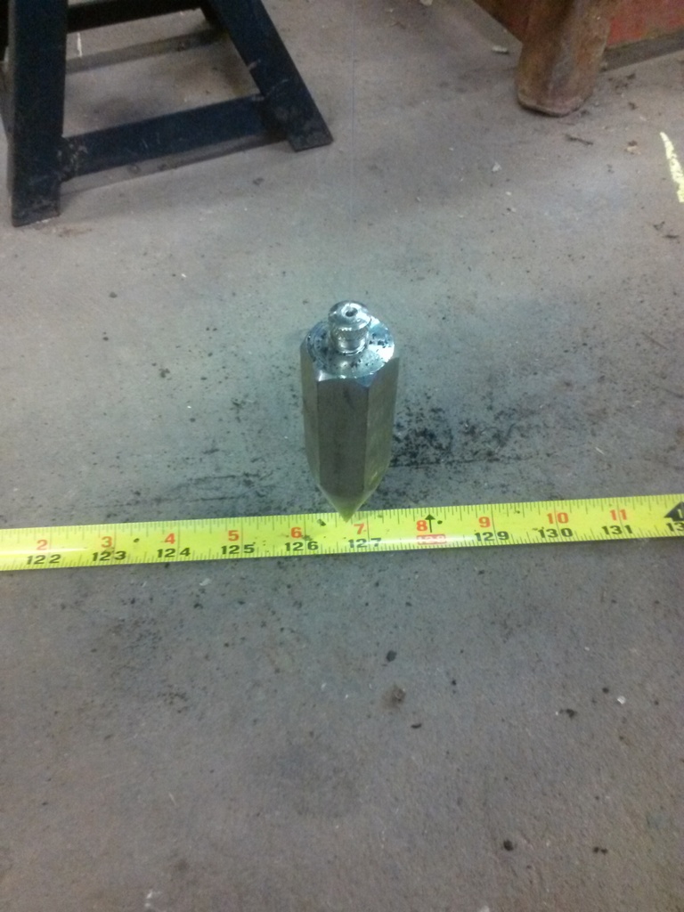
Plumb bobs are what I like to use. Two plumbs hanging from the LCA bolt on each side of the frame, and the center plumb hanging from the crank pulley bolt.
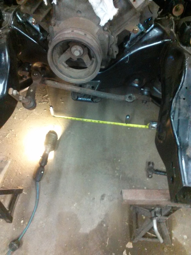
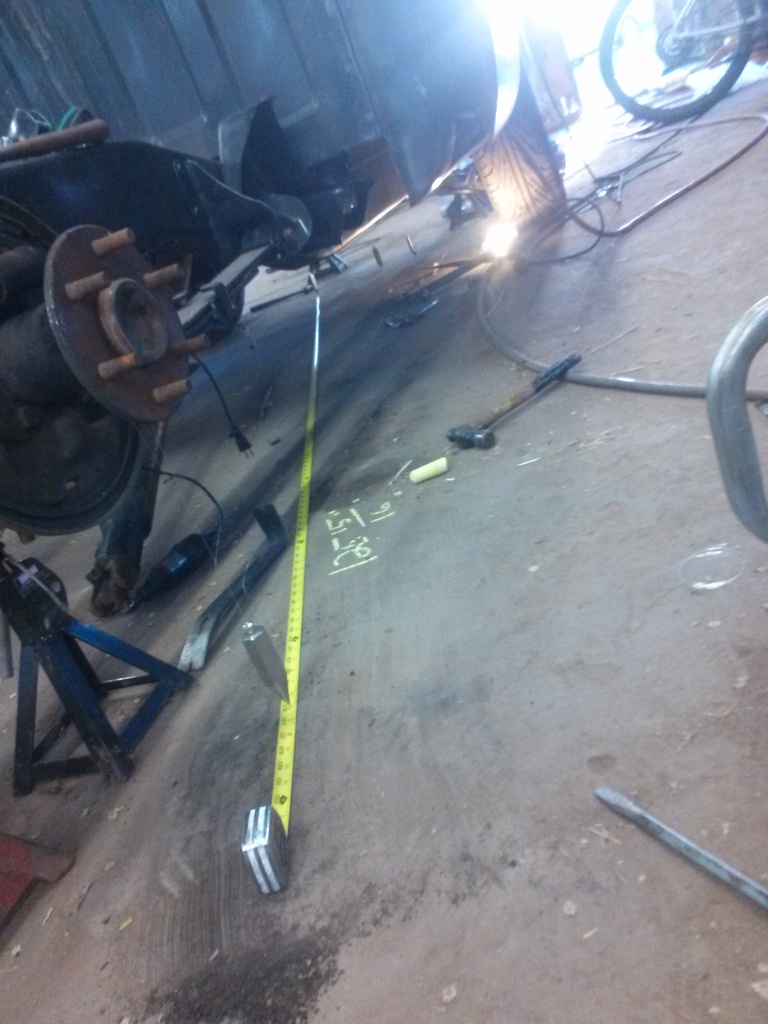
Measure between two points of reference that are the same on both sides to find center. I used the LCA bolt holes.
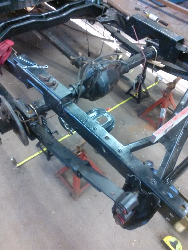
Same thing as above, but in the back this time.
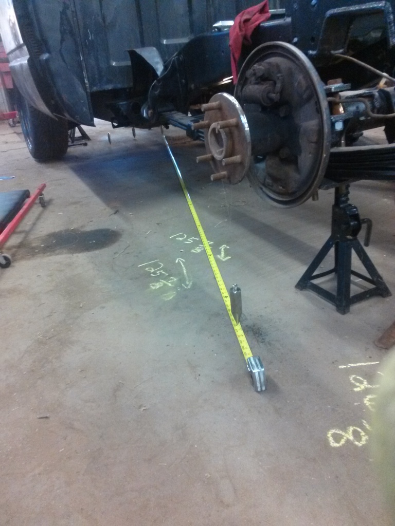
Measuring diagonals to check square.
Looking good! Measuring from different points of reference will give you an idea of how to get everything set up square.
More diagonal measurements.

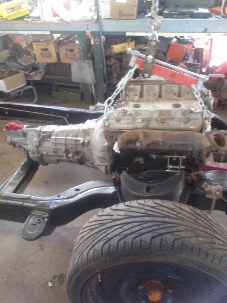
One of the “last” times setting the engine…. HAHA yeah right.
The victim is a 1990 Chevrolet Silverado.

Dragging an F150 about 130 miles.
The pics below show the transport wheels with some moons I just set on to see how they might look.


Starting to tear apart the truck.

Bare frame back from blaster

My dad and I painted the frame with rustoleum on a still day.

Frame before C notch cutting. You Can see the reinforcement I added to brace the frame for the cutting

Working on the C notch


When I was mocking up the c notch I decided to go ahead and build it as high as possible since I was welding it in anyways. So the c notch itself is fully welded, the frame is reinforced with uprights immediately in front of and behind cut and a horizontal reinforcement laid across the cut on the TOP side of the frame. Finally, I boxed in the frame with plate steel.

This picture shows the upright welded in front of the c notch cut. Also, you can see the horizontal member a piece of 2x3 square tube laid over the top of the frame which extends approximately 3 to 4 inches beyond the cut.

Another shot of one of the uprights

C notch is fully welded

Starting to box in the frame on the inside for further reinforcement. Also visible are the holes where I rosette welded the inside reinforcement plate to the uprights
Below are some pics that show the finised c notch.

I made this rough drawing real quick for someone who inquired about the way I built this notch


------------------------------
On to the suspension…. Time to remove all the old bushings to replace them with poly.
 .
.I found the easiest way to remove the OEM rubber bushings was to just light them on fire with the torch

The inner metal sleeves will actually start to slide out and in some cases will actually “shoot” out a few inches.

Both control arms with bushings burning

Removing the leaf spring bushings

Once the majority of the OEM rubber bushing is gone, you can grab a screwdriver, scrape out the last little bit, maybe stuff some rags through it with some solvent. Somewhat visible in this picture is the metal sleeve inside the spring eye. Using the poly bushings I had required removing this inner metal sleeve. An impact hammer, chisels and a cutoff wheel made relatively easy work of it.
I had to machine some spacers or sleeves to make the bushings fit the shackles as they were too small for some odd reason.

One of the first dry fits for the LQ4 in the frame. Interesting factoid, I was planning on using polyurethane engine mounts but…… I had forgotten the fact that you have to drop the lower control arms to back up the nuts that hold the rubber/poly mounts to the frame. All this just to change engine mounts, plus I had quite a bit of fun stuffing all four control arms back into the frame with the poly bushings.

Not wanting to deal with that again, plus the fact that racetruck
……. “Solid mounts it is” I said outloud.Squaring everything up in the frame:

I established a centerline for a point of reference to begin measuring.

Plumb bobs are what I like to use. Two plumbs hanging from the LCA bolt on each side of the frame, and the center plumb hanging from the crank pulley bolt.

Measure between two points of reference that are the same on both sides to find center. I used the LCA bolt holes.

Same thing as above, but in the back this time.

Measuring diagonals to check square.

Looking good! Measuring from different points of reference will give you an idea of how to get everything set up square.

More diagonal measurements.

One of the “last” times setting the engine…. HAHA yeah right.
Last edited by ElQueF�r; 03-27-2017 at 04:38 AM.
 03-20-2017, 12:47 PM
#2

Stock TBI fuel pump coming out.

Putting the TrueTrac back together after pulling the axle shafts to install NBS disc brakes on the OBS 14 bolt. Oddly I cannot find any photos of the brake assembly coming together, I’ll have to snap some other photos since that part is done.

Starting to figure out the racetronix fuel pump hotwire harness. I have to say, their whole company attitude which I learned about after having already bought this thing makes me not want to do business with them. Hopefully I hooked this up correct, it seems simple enough but some directions would be great.

Starting to solder the wires together for the fuel pump hotwire install. I like to double shrink wrap wires sometimes.

New LSx T56 input shaft, front plate, bellhousing and shims. Converting a SBC T56 to LSx seems to be the most economical way of obtaining an LSx T56.

Shims and bearing races.

A quick but very effective tool I slapped together. It’s made of scrap steel I had laying around. This lets you use an engine stand hold the T56. It mounts on the two ears on the side of the trans case.

T56 on the homemade fixture installed on an engine stand.

Shims. I actually had to go buy a shim from the stealership. I Wanna say .012”?? I had to do this in order to get the correct preload and endplay setup on this gearbox.

Starting to slide the back end of the tranny back together.

Transmission parts laid out.

Homemade T56 endplay tool! Some metric allthread and a few nuts.
And now some bodywork!

As usual on these trucks….. The cab corner is trashed.

And the rockers aren’t much better.

Starting to cut out the bad metal.

Looks worse once it’s off!

Headed to the parts truck with the rusty piece as a template for good metal.

I bought this parts truck for $200. Sold the trans for $200, the engine for $500 and probably about $100 in little odds and ends, and it still has plenty of good parts and sheetmetal.

Rusty piece beside new patch.

Strip the paint off so you don’t have to fight with it while welding.

Starting to weld in the patch. No continuous weld beads here, just a series of tacks to keep heat and therefore warpage to a minimum.

Continuing on with the removal of the cab corner. Some spot welds had to be drilled where the sheetmetal meets the back of the cab.

I’m convinced the foam stuff GM sprays in here collects water and helps rust out these cab corners. I scraped and burned off what I could get to. Just slightly visible is the rust on the inner cab corner.

Axed off a big piece of the corner of this wrecked 1 ton to repair the inner corner on my truck.

Time to peel off the banged up outer corner.

Cab cleaned and ready to accept new metal.

Inner cab corner from the 1 ton.

Test fitting.

Starting to weld in the cab corner superstructure.

Weld, grind, repeat.

Just a few spots left to hit with the welder and we’re done here.
Last edited by ElQueF�r; 03-27-2017 at 04:41 AM.
03-20-2017, 12:50 PM
#3

Rocker panel mostly finished, Won’t take much filler to make this invisible.

Last couple holes on the inner cab corner patch welded, a touch of primer.

Bodyworking the door , rocker and corner

Door before bodywork.

Pulling a dent out of the other door.

More bodywork of the passenger door.

Starting to figure out what wires might go where. Fender more or less ready for paint.


Final bodywork on the driver door.

Hood ready for paint.

Bodyworking the rest of the cab.

More cab bodywork.

Corner turned out good.

Getting the jambs ready for paint.

Jambwork.

Finished fender

Cab nearly finished.

Fenders laid on parts truck.

I had to respray some panels, no big deal, the Blitz Black is cheap enough, and pretty easy to work with once you get some experience built up.

Hittin’ the door.

S475 1.32 A/R T6 Borg Warner turbo!

“Rocket Fuel”

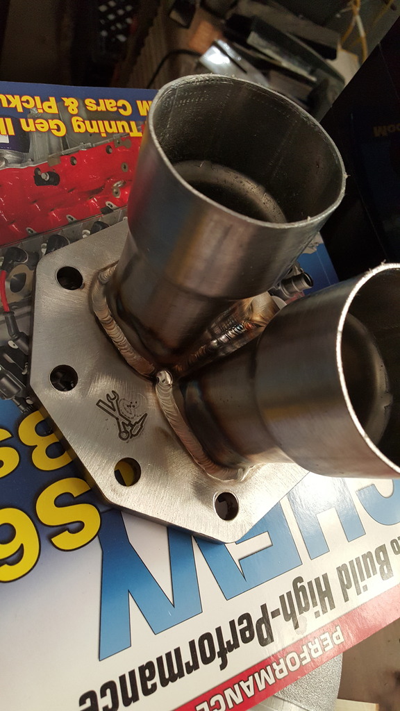
Got this mild steel T6 crossover flange from Monkey Fab. Pretty happy with it! It is well built.


Finished rocker patch on the passenger side.

Rocker patch on passenger side.

Time to mask off!


A lot of the parts for the GMT 400s are interchangeable. The doors apparently are not one of them. I should have been paying more attention, but the early doors have this indention to clear the inner metal panel and also for the pull handle to attach. The door I bodyworked and painted was from a 2000 Silverado “Classic” 1 ton. I decided to just weld this in since it’s covered by the door panel anyways.


Last edited by ElQueF�r; 03-27-2017 at 04:44 AM.
03-20-2017, 12:50 PM
#4


I put the first AN bung right the way of an oil pan bolt….
No big deal, just weld it up and grab another one.

Checking out pilot bushings. I never liked pilot bearings, especially having had one that destroyed an input shaft once.

Bolting the clutch components on…. Fylwheel installed.

Pressure plate bolts.

Using a T56 input shaft to install the LS7 disc and pressure plate.

T56 after remote bleeder and main hydraulic line installed.

Adapter fittings and AN hose for clutch hydraulics.

Removing the stock quick disconnect fitting from the clutch slave to connect the adapter fitting for AN hose.

Quick disconnect fitting removed.

A roll pin retains the fitting here.

T56 with the new slave and AN lines installed for master cylinder connection and remote bleeder.

Bolting up the T56 to the LQ4.

I had to turn down the remote bleeder fitting that goes into the slave cylinder in order to get it to slide in. It was a few thousandths oversize, easily corrected with emery cloth and a way to spin the fitting like a drill.

Laying the turbo under the hood of the K5 to check rough fit of the turbo.


Starting to modify the truck manifolds

I had to kick the collector up at a more straight angle to connect to the crossover flange. The manifolds weld very easily. I used a set of truck manifolds flipped upside down.

Laying out the crossover pipe routing with the manifolds.

Crossover pipe starting to come together.

More crossover pipe work.

Crossover pipe mostly finished.

Crossover pipe.

This is the passenger side truck manifold, flipped. The flange is now pointing almost straight up after repositioning.

I shaved the bosses for the heat shields, the casting numbers and all other superfluous BS.

Cut, weld, grind…………

Still smoothing out the manifolds.

Starting to build the 5” downpipe.

This is the beginning of several mandrel bends and pie cuts that make up the downpipe.

First couple of rough bends figured out.

This is the finished 5 inch downpipe tacked up before final welding.

Wastegate mount shown here. Made both out of pieces cut up from a junk header. Looks to be stainless maybe?

Both driver and passenger wastegate mounts rough cut.

Passenger side wastegate mount hole cut.

Driver side wastegate mount tacked on.

View into the D/S wastegate.

Closeup of downpipe.

Intercooler!
Last edited by ElQueF�r; 03-27-2017 at 04:46 AM.
03-20-2017, 12:51 PM
#5


Starting to cut out all the pie cuts for the compressor discharge pipe.


Compressor discharge pipe coming together.

Mocking up the intercooler. The upper mounts are made from chain link fence tension rod that bolts inline with the a/c condenser mounts.

All the pie cuts are done for the compressor discharge pipe.

Starting to weld the pie cuts together.


Intercooler piping coming together. Only a slight trimming of the grille was all that was required to fit.


Shot of hotside piping.


The 5” downpipe tucks pretty nice even as big as it is.

Another downpipe shot.

And yet another downpipe shot.


Compressor discharge pipe.

I had originally planned on using the TBI a/c compressor but decided to use the LS style and notch the frame. The frame is thicker here to space the idler arm over. Even after cutting the frame rail is still wider than the other side.

Starting to make cardboard templates for boxing in the frame notch.


Templates done.

A/c notch welded and primed.

A/c notch Painted.

LS9 headgaskets.

7 Layers I think?

One head off for LS9 gaskets.

Both heads off.

ARP head bolts and stock pushrods.
Last edited by ElQueF�r; 03-27-2017 at 04:48 AM.
03-20-2017, 12:52 PM
#6

Whoops

I made a blockoff plate for the CCP valvethingmabob. IAT location perhaps?

I drilled and tapped the oil cooler blockoff to � NPT and used a 6AN to pipe thread fitting for the oil feed to the turbo.


After learning about decapping injectors from sloppy and elsewhere I figured I’d give it a try. The injector on the left is stock. The injector in the middle shows the cap as it has “lifted” from the injector during grinding, it’s barely attached at this point. The far right injector shows what you end up with. Keep the grinder away from the poppet valve in the center, could ruin an injector if you’re not careful while grinding off the cap.
My understanding is that while this injector mod increases flow, it also changes the spray from a more finely atomized mist to more of a faucet just shooting fuel in. The normal turbulence in the charge pipes and intake in a turbo application should make up for this. I seem to recall that this is actualy pretty similar to what the aftermarket injectors are anyways.

New AC Delco starter and bolts.

Braided AN line with -6 feed and -12 AN drain.

454 SS steering box. Should be a little quicker than normal truck boxes for these trucks.

Turbo oil drain flange


Fabbed up an upper charge pipe and radiator hose mount.

Hotside coldside, belt and hoses routed.

-12AN braided turbo oil drain line.


Fenders and Grille pulled back off for more turbo work.

This is a junkyard steering shaft from an early 90’s Jeep Cherokee which is mostly a bolt in deal and eliminated the sloppy ragjoint. Visible are the Solid mounts, Poly bushings, braided turbo oil line, and 4 AWG ground wire.

Factory busbar. Far left is the fuel pump hotwire fuse. The two thick red wires are 4 AWG. The one on the right comes from the alternator, and the one on the left connects to the battery which I remote mounted. The red wire in the middle is the +12v wire to the LS engine harness.

This is the harness before I rerouted it.

I Remote mounted the battery beneath the bed floor and behind the cab.
Last edited by ElQueF�r; 03-27-2017 at 05:11 AM.
Trending Topics


 03-27-2017, 05:08 AM
#14
I updated the posts a little bit. Mainly tried to tighten up the wording and add some descriptions.
Thanks!

Thanks!
 Thankyou!
Thanks! And great idea! I tightened up the posts a little bit and added some more descriptions.
Yes I have hahaha. Thankyou!
Thankyou! The turbo trashtruck is now running!
Thanks!

Thanks!
Thankyou!Yes I have hahaha. Thankyou!
Thankyou! The turbo trashtruck is now running!
Thanks!
Last edited by ElQueF�r; 03-27-2017 at 05:16 AM.
03-27-2017, 05:16 AM
#15
Just got this thing fired up for the first time. Here is a short clip of it running on the stock 411 LS1 tune and VATS shutting it off at around 3 seconds. HPTuners should be in the mailbox today!!!
03-27-2017, 04:55 PM
#16
I just got HPTuners in the mail and have been playing around with it.
I've done some OBD1 tuning so I know the basics, but I'm new to this whole credits per vehicle thing.
One big question at this point.. What base tune do I download to start with from the HPTuners repository for this setup?
I've done some OBD1 tuning so I know the basics, but I'm new to this whole credits per vehicle thing.
One big question at this point.. What base tune do I download to start with from the HPTuners repository for this setup?
03-27-2017, 08:24 PM
#17
before you license your pcm, scan it and see what OS it's running. make sure there is a 2 or 3 bar speed density OS upgrade for it.
but basically you license your pcm, then find a file that will get you close and then open it as a "compare" file ( say no thanks to licensing it) and then copy and paste all the tables over.
also make sure to set the maf fail to 0 hz so it goes into open loop speed density
you have a ton of reading to do!
03-27-2017, 11:34 PM
#19
Ok, I understand now. License only the PCM after verifying custom 2 or 3 bar SD OS capability, and using the stock PCM bin image as a starting point, do a compare and copy the values from whatever bin you use that you think ought to be close to your particular setup.
I actually have been browsing that thread over the past couple days, glad it's spot on!
Thanks for your help! I'm going to play with this a little tonight and see what I can get done on it.
I actually have been browsing that thread over the past couple days, glad it's spot on!
Thanks for your help! I'm going to play with this a little tonight and see what I can get done on it.
02-16-2019, 12:49 AM
#20
I don't remember if I posted this long winded rambletron video elsewhere on the site, but I hate leaving things where they seem unfinished.
So here is the finished product of the insanity pictured in this thread.
So here is the finished product of the insanity pictured in this thread.