
Help Wiring Truck Harness and PCM W/T56
 06-16-2009, 07:21 PM
#1
TECH Apprentice
Thread Starter
iTrader: (4)

Join Date: Dec 2008
Location: Broken Arrow, OK
Posts: 317
Likes: 0
Received 0 Likes
on
0 Posts
Ok, I need a little help with my wiring. My PCM has been reflashed with all emissions removed as well as Vatts removed and I'm trying to make sure I am wiring everything up correctly. My harness is from a 05 Silverado and attached is my Pin out doc with all the wires I have removed Highlighted in Red. I am running DBW and I also want the PCM to control the A/C, but did I remove all Automatic Transmission related wiring?
I've been trying to use the following link as well.
http://www.lt1swap.com/2000harness.htm
Also, I'm a little confused about the following.
I've cut all wires from the C100 and they are to be wired into the Dash. I've also cut all wires from C2 plug and from what I understand they need to be wired into my chasis's fuse boxes, but I now only have 2 wires remaining for plug C152. I assume that is because the removal of all emissions, but where do these wires need to go?
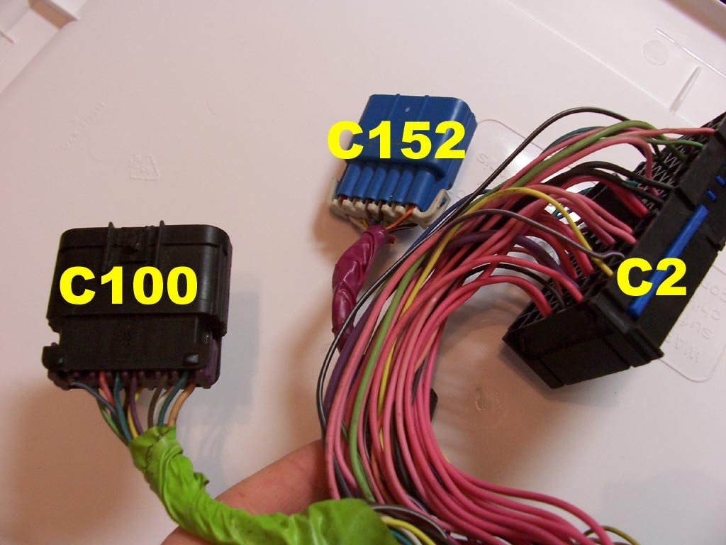
Also, can anyone identify this plug?

Thanks for any help.
I've been trying to use the following link as well.
http://www.lt1swap.com/2000harness.htm
Also, I'm a little confused about the following.
I've cut all wires from the C100 and they are to be wired into the Dash. I've also cut all wires from C2 plug and from what I understand they need to be wired into my chasis's fuse boxes, but I now only have 2 wires remaining for plug C152. I assume that is because the removal of all emissions, but where do these wires need to go?
Also, can anyone identify this plug?
Thanks for any help.
 06-16-2009, 08:50 PM
#2

Are these the wire colors?
Connector Part Information
12191065
16-Way F Micro-Pack 100 Series (GY)
Pin
Wire Color
Circuit No.
Function
1
D-GN
485
TP Sensor 1 Signal
2
GY
416
5-Volt Reference
3
BK
452
Low Reference
4
D-BU
84
Cruise Control Set/Coast Switch Signal
5
GY/BK
87
Cruise Control Resume/Accel Switch Signal
6
L-BU
1320
CHMSL Supply Voltage
7
PK
1339
Ignition 1 Voltage
8
BN
582
TAC Motor Control - 2
9
L-BU/BK
1688
5-Volt Reference
10
BK/WH
1704
Low Reference
11
PU
486
TP Sensor 2 Signal
12
OG/BK
1061
UART Serial Data
13
D-BU/WH
774
UART Serial Data
14
GY
397
Cruise Control On Switch Signal
15
BK
550
Ground
16
YE
581
TAC Motor Control - 1
If so, its to the TAC module
06-16-2009, 08:53 PM
#3
C152 Chassis Harness to Engine Harness
Connector Part Information
15373533
12-Way F GT 150 SLD 4.0 (NA)
Connector Part Information
15373547
12-Way M GT 150 SLD 4.0 (NA)
Pin
Wire Color
Circuit No.
Function
Pin
Wire Color
Circuit No.
Function
A
--
--
Not Used
A
--
--
Not Used
B
TN
1465
Fuel Pump Relay Control - Secondary - Dual Fuel Tanks (Gas)
B
TN
1465
Fuel Pump Relay Control - Secondary - Dual Fuel Tanks (Gas)
C
GY
474
5-Volt Reference (Gas)
C
GY
474
5-Volt Reference (Gas)
D
D-GN
890
Fuel Tank Pressure Sensor Signal (Gas)
D
D-GN
890
Fuel Tank Pressure Sensor Signal (Gas)
E
YE/BK
1827
Vehicle Speed Signal
E
YE/BK
1827
Vehicle Speed Signal
F
WH
1310
EVAP Canister Vent Solenoid Control (Gas)
F
WH
1310
EVAP Canister Vent Solenoid Control (Gas)
G
--
--
Not Used
G
--
--
Not Used
H
D-BU
1936
Fuel Level Sensor Signal - Secondary - Dual Fuel Tanks
H
D-BU
1936
Fuel Level Sensor Signal - Secondary - Dual Fuel Tanks (Gas)
J
BK
470
Low Reference
J
BK
470
Low Reference
K
PU
1589
Fuel Level Sensor Signal - Primary
K
PU
1589
Fuel Level Sensor Signal - Primary
L
TN/BK
464
Delivered Torque Signal (NW7)
L
TN/BK
464
Delivered Torque Signal (NW7)
M
OG/BK
463
Requested Torque Signal
M
OG/BK
463
Requested Torque Signal
Connector Part Information
15373533
12-Way F GT 150 SLD 4.0 (NA)
Connector Part Information
15373547
12-Way M GT 150 SLD 4.0 (NA)
Pin
Wire Color
Circuit No.
Function
Pin
Wire Color
Circuit No.
Function
A
--
--
Not Used
A
--
--
Not Used
B
TN
1465
Fuel Pump Relay Control - Secondary - Dual Fuel Tanks (Gas)
B
TN
1465
Fuel Pump Relay Control - Secondary - Dual Fuel Tanks (Gas)
C
GY
474
5-Volt Reference (Gas)
C
GY
474
5-Volt Reference (Gas)
D
D-GN
890
Fuel Tank Pressure Sensor Signal (Gas)
D
D-GN
890
Fuel Tank Pressure Sensor Signal (Gas)
E
YE/BK
1827
Vehicle Speed Signal
E
YE/BK
1827
Vehicle Speed Signal
F
WH
1310
EVAP Canister Vent Solenoid Control (Gas)
F
WH
1310
EVAP Canister Vent Solenoid Control (Gas)
G
--
--
Not Used
G
--
--
Not Used
H
D-BU
1936
Fuel Level Sensor Signal - Secondary - Dual Fuel Tanks
H
D-BU
1936
Fuel Level Sensor Signal - Secondary - Dual Fuel Tanks (Gas)
J
BK
470
Low Reference
J
BK
470
Low Reference
K
PU
1589
Fuel Level Sensor Signal - Primary
K
PU
1589
Fuel Level Sensor Signal - Primary
L
TN/BK
464
Delivered Torque Signal (NW7)
L
TN/BK
464
Delivered Torque Signal (NW7)
M
OG/BK
463
Requested Torque Signal
M
OG/BK
463
Requested Torque Signal
06-16-2009, 09:00 PM
#4
Your 05 harness is a drive by wire harness and the connector goes to the throttle actuator module located on thw firewall above the gas pedal on the firewall side. You need the matching TACC module and a gas pedal.
Go here for drive by wire details:
www.chevythunder.com
Info you are looking for is at the very bottom of web page.
Obviously you PCM file needs set up correctly for DBW.
Go here for drive by wire details:
www.chevythunder.com
Info you are looking for is at the very bottom of web page.
Obviously you PCM file needs set up correctly for DBW.
06-16-2009, 09:09 PM
#5
TECH Apprentice
Thread Starter
iTrader: (4)
Join Date: Dec 2008
Location: Broken Arrow, OK
Posts: 317
Likes: 0
Received 0 Likes
on
0 Posts
Hey Joe, how was your trip? Thanks for the post, apparently that is my Tac Module plug. So, I guess I need to leave that one intact right? Oh, and apparently that junkyard that I bought my PCM and pedal from didn't send me the TAC module. Which from what I understand I have to have since I'm DBW.
06-16-2009, 09:11 PM
#6
TECH Apprentice
Thread Starter
iTrader: (4)
Join Date: Dec 2008
Location: Broken Arrow, OK
Posts: 317
Likes: 0
Received 0 Likes
on
0 Posts
Your 05 harness is a drive by wire harness and the connector goes to the throttle actuator module located on thw firewall above the gas pedal on the firewall side. You need the matching TACC module and a gas pedal.
Go here for drive by wire details:
www.chevythunder.com
Info you are looking for is at the very bottom of web page.
Obviously you PCM file needs set up correctly for DBW.
Go here for drive by wire details:
www.chevythunder.com
Info you are looking for is at the very bottom of web page.
Obviously you PCM file needs set up correctly for DBW.
06-17-2009, 09:42 PM
#7
TECH Apprentice
Thread Starter
iTrader: (4)
Join Date: Dec 2008
Location: Broken Arrow, OK
Posts: 317
Likes: 0
Received 0 Likes
on
0 Posts
Ok, another quick question. I'm still labeling my extra wires and I'm not sure if I really need a few of them. I have these 4 wires on the Green C1. Now, I had all emissions tuned out of my PCM so do I need these, aren't they 02 sensors?
26
TAN
1667
HO2S Low Signal - Bank 2 Sensor 1
29
TAN
1664
HO2S Low Signal - Bank 1 Sensor 1
66
PPL
1666
HO2S High Signal - Bank 2 Sensor 1
69
PPL/WHT
1665
HO2S High Signal - Bank 1 Sensor 1
26
TAN
1667
HO2S Low Signal - Bank 2 Sensor 1
29
TAN
1664
HO2S Low Signal - Bank 1 Sensor 1
66
PPL
1666
HO2S High Signal - Bank 2 Sensor 1
69
PPL/WHT
1665
HO2S High Signal - Bank 1 Sensor 1
Trending Topics
06-18-2009, 01:25 AM
#8
On The Tree

Join Date: Jul 2004
Location: Stockholm, Sweden
Posts: 166
Likes: 0
Received 0 Likes
on
0 Posts

You need one O2 sensor on each side for the fuel injection to work properly. It hasn't to do with the emision, more with the proper amount of fuel for each burn. Without them the ECU will make the engine run rich.
Jan
Jan
06-18-2009, 01:56 AM
#9
Hey Joe, how was your trip? Thanks for the post, apparently that is my Tac Module plug. So, I guess I need to leave that one intact right? Oh, and apparently that junkyard that I bought my PCM and pedal from didn't send me the TAC module. Which from what I understand I have to have since I'm DBW.
06-18-2009, 08:12 AM
#10
BTW need to be clear when we say you only need two O2 sensors. You need the front two to adjust the air/fuel mixture. All associated rear o2 wires can be deleted.
I'm doing several LS based DBW and DBC swaps now including 5.3L into a 82 GMC 4x4, 5.7L into a 64 imp SS and DBW 6.0L into my 96 caprice police car.
I'm puting together a spreadsheet/list of truck and F-body pinouts as they are different for each chassis. The list shows what all can be deleted. Makes troubleshooting easier.
PM me your email and I can send you the 2005 DBW wiring diagrams.
06-26-2009, 08:56 PM
#11
TECH Apprentice
Thread Starter
iTrader: (4)
Join Date: Dec 2008
Location: Broken Arrow, OK
Posts: 317
Likes: 0
Received 0 Likes
on
0 Posts
Ok, I working on my harness right now and I'm wondering how much I need to extend my harness to place the PCM in the stock location (passenger side foot). Anyone?
06-28-2009, 06:47 PM
#13
TECH Apprentice
Thread Starter
iTrader: (4)
Join Date: Dec 2008
Location: Broken Arrow, OK
Posts: 317
Likes: 0
Received 0 Likes
on
0 Posts
Thanks Joe, I guess I will try it out and see if I'm good.
Ok, 1 more thing. I'm trying to figure out what gauge wire I should use to run all the Pink wires to the ingnition relay. I've been trying to figure it out using a wire gauge table, but apparently I'm not that skilled. Also, what is the best method to solder all the wires to one.
Ok, 1 more thing. I'm trying to figure out what gauge wire I should use to run all the Pink wires to the ingnition relay. I've been trying to figure it out using a wire gauge table, but apparently I'm not that skilled. Also, what is the best method to solder all the wires to one.
07-02-2009, 10:59 AM
#15
TECH Apprentice
Thread Starter
iTrader: (4)
Join Date: Dec 2008
Location: Broken Arrow, OK
Posts: 317
Likes: 0
Received 0 Likes
on
0 Posts
Ok, I've figured out the wire gauge but hopefully there are some 240sx guys on here that can shed a little light on this for me. I'm attempting this process right now and I've been bouncing a couple of questions off of txredxj (thanks again) but I have a couple other questions.
I have this Pin out for the F3 plug and I have been trying to split it up from the Ka harness, but am I going about this the right way. I was thinking that the F3 plug probably had the fuse box and windshield wiper plugs wired into it so it would be better to remove it as a whole, but would I be better off just hacking off the F3 with about 6 inches of wires and wiring it into the LS harness or should I contiune the process of delooming the entire KA engine harness?
Also, has anyone successfuly hooked up their consult port using the F3? I will be running A/C controlled by the PCM as well so any help there would be greatly appreiciated.
Another member on Silviav8forums posted the following info:
Originally Posted by jmauld
Okay, so I'm working on the wiring now. Since I've gained a lot of knowledge from you guys (and I have plenty of questions left), I thought that I could give something back by documenting this as I go, and hopefully making it easier for those in the future.
I used a combination of the FSM and this document to do what I've done so far.

The items below that are in black, I have left in my connector for later use.
The items in red have been removed.
Items in Green, I am still undecided on, so please give feedback if you can.
- 1-black/red, ignition lead to injectors, coil
- 2- EMPTY
- 3-blue/red, rear defogger/electrical load signal
- 4-pink, washer switch
- 5-light green, ignition lead to wiper motor
- 6-light green/black, wiper motor high
- 7-light green/red, wiper motor low
- 8-brown, wiper off/int switch
- 9- EMPTY
- 10-black/yellow, fuel pump signal to F23, IACV-IAA
- 11-black/pink, fuel pump relay signal
- 12-orange, headlamp diode According to the schematic this is used by the ECM for a malfunction indicator?
- 13- EMPTY
- 14- EMPTY
- 15-purple/white, P/S oil pressure switch
- 16-yellow/black, AC switch
- 17-red, battery lead to ECCS relay I believe this wire and the associated relay can be removed?
- 18-brown, igniton lead to O2 sensors, EGRC solenoid, EVAP purge/vent solenoids, IACV, TPS
- 19- EMPTY
- 20-red, GST port (Can these be used to connect the OBDII port to the GM ECU?)
- 21-yellow, GST port
- 22-green, CONSULT port
- 23-green/white, CONSULT port
- 24-yellow/green, VSS signal
- 25-orange/blue, cooling fan high signal
- 26-yellow/red, tachometer
- 27-blue/yellow, wiper intermittent switch
- 28-yellow, temp gauge sending wire
- 29-black/white, ambient air temperature switch
- 30-orange, MIL lamp
- 31-blue/white, ASCD actuator power
- 32-blue, ASCD air valve
- 33-yellow/blue, 5th gear position switch
- 34-orange, start signal
- 35- EMPTY
- 36- EMPTY
- 37-orange/blue, recirculation relay
- 38-green/black, CONSULT port
- 39- EMPTY
- 40-green/orange, neutral position switch
- 41-blue/green, cooling fan low signal
- 42-purple, wiper variable intermittent switch
- 43-black/pink, triple pressure switch signal (leave for AC)?
- 44-blue/red, IACV-FICD signal
- 45-orange/black, triple pressure switch line
- 46-orange/blue, AC thermo control amp
- 47-green/yellow, ASCD release valve
- 48-blue/black, ASCD vacuum motor
Any of the AC leads can be removed if you are not retaining AC. Some of them may be removed anyway, but I am not planning on doing the AC until next year, so I am leaving the wires for now.
There is an additional plug for the ABS.
In this plug, there are three green wires that communication to the Nissan ECM. I'm told that these can be removed. There is also a wire that connects to pin 24 of the F3 plug. The VSS lead. This should stay connected to the ABS harness and connected with the F3 plug to the output of the Dakota Digital converter box.
*Disclaimer, my info is specific to the S14, your wiring may be different.
Once I start integrating this into the GM Harness, I'll add that information as well.
I used a combination of the FSM and this document to do what I've done so far.
The items below that are in black, I have left in my connector for later use.
The items in red have been removed.
Items in Green, I am still undecided on, so please give feedback if you can.
- 1-black/red, ignition lead to injectors, coil
- 2- EMPTY
- 3-blue/red, rear defogger/electrical load signal
- 4-pink, washer switch
- 5-light green, ignition lead to wiper motor
- 6-light green/black, wiper motor high
- 7-light green/red, wiper motor low
- 8-brown, wiper off/int switch
- 9- EMPTY
- 10-black/yellow, fuel pump signal to F23, IACV-IAA
- 11-black/pink, fuel pump relay signal
- 12-orange, headlamp diode According to the schematic this is used by the ECM for a malfunction indicator?
- 13- EMPTY
- 14- EMPTY
- 15-purple/white, P/S oil pressure switch
- 16-yellow/black, AC switch
- 17-red, battery lead to ECCS relay I believe this wire and the associated relay can be removed?
- 18-brown, igniton lead to O2 sensors, EGRC solenoid, EVAP purge/vent solenoids, IACV, TPS
- 19- EMPTY
- 20-red, GST port (Can these be used to connect the OBDII port to the GM ECU?)
- 21-yellow, GST port
- 22-green, CONSULT port
- 23-green/white, CONSULT port
- 24-yellow/green, VSS signal
- 25-orange/blue, cooling fan high signal
- 26-yellow/red, tachometer
- 27-blue/yellow, wiper intermittent switch
- 28-yellow, temp gauge sending wire
- 29-black/white, ambient air temperature switch
- 30-orange, MIL lamp
- 31-blue/white, ASCD actuator power
- 32-blue, ASCD air valve
- 33-yellow/blue, 5th gear position switch
- 34-orange, start signal
- 35- EMPTY
- 36- EMPTY
- 37-orange/blue, recirculation relay
- 38-green/black, CONSULT port
- 39- EMPTY
- 40-green/orange, neutral position switch
- 41-blue/green, cooling fan low signal
- 42-purple, wiper variable intermittent switch
- 43-black/pink, triple pressure switch signal (leave for AC)?
- 44-blue/red, IACV-FICD signal
- 45-orange/black, triple pressure switch line
- 46-orange/blue, AC thermo control amp
- 47-green/yellow, ASCD release valve
- 48-blue/black, ASCD vacuum motor
Any of the AC leads can be removed if you are not retaining AC. Some of them may be removed anyway, but I am not planning on doing the AC until next year, so I am leaving the wires for now.
There is an additional plug for the ABS.
In this plug, there are three green wires that communication to the Nissan ECM. I'm told that these can be removed. There is also a wire that connects to pin 24 of the F3 plug. The VSS lead. This should stay connected to the ABS harness and connected with the F3 plug to the output of the Dakota Digital converter box.
*Disclaimer, my info is specific to the S14, your wiring may be different.
Once I start integrating this into the GM Harness, I'll add that information as well.
07-08-2009, 08:53 PM
#16
TECH Apprentice
Thread Starter
iTrader: (4)
Join Date: Dec 2008
Location: Broken Arrow, OK
Posts: 317
Likes: 0
Received 0 Likes
on
0 Posts
Ok, can some one please help me out. I think I almost have this completed but I have the following wires and I don't know where they should go.
From PCM C1
39 YEL/BLK 625 Starter Enable Relay Control
From C2 - Underhood Fuseblock 2005
F3 PU 806 Crank Voltage
From PCM C1
39 YEL/BLK 625 Starter Enable Relay Control
From C2 - Underhood Fuseblock 2005
F3 PU 806 Crank Voltage