


ModularTurbo/CBR F2 Twin Turbo kit install
Thread Starter
FormerVendor
iTrader: (14)
Joined: Jun 2008
Posts: 1,765
Likes: 2
From: Homestead, FL
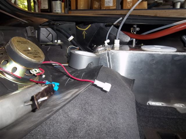
The water lines for the air to water intecooler along with the coolant recovery line
and wiring harness for the intercooler pump are run through the rocker panels.
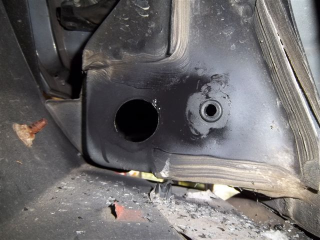
First we start by cutting holes.
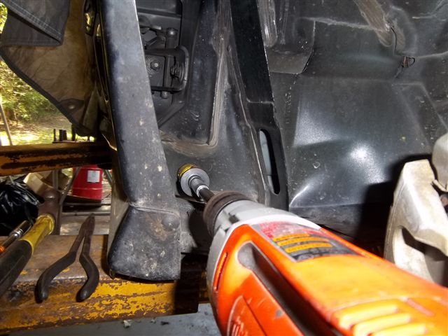
This is the passenger side, the small hole is for the coolant recovery line.
Notice the rubber grommet.
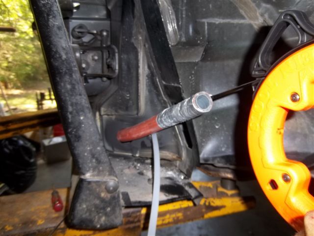
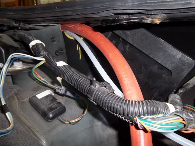
We feed a electricians fish tape from front to rear to pull the hoses through the rocker panel.
Chris feeds the hose over the wheel tub into the rocker panel as someone pulls on the fish tap.
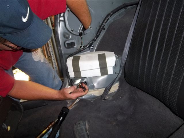
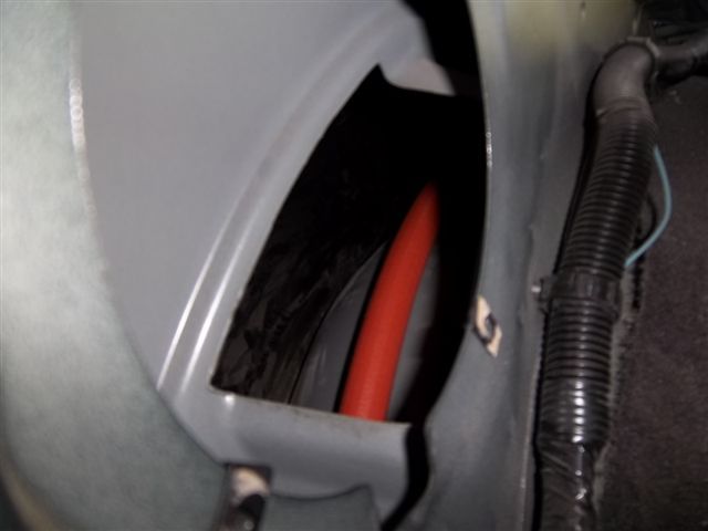
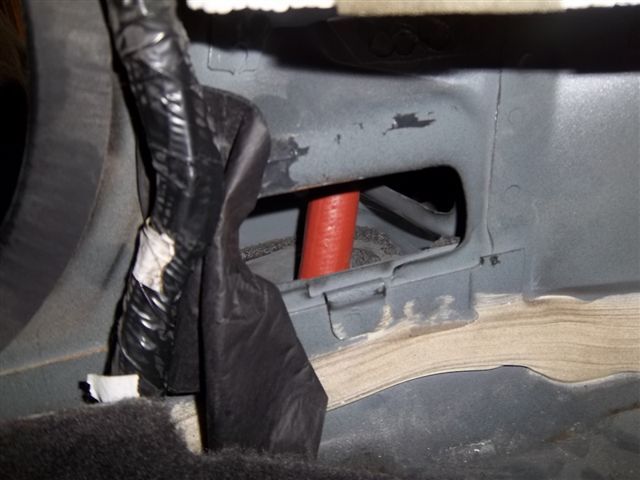
You can see were the hose enters the rocker panel.
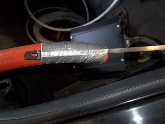
There is a piece of foam covering a hole in the top of the rocker panel on both sides.
The hole is about the size of an egg, perfect for water lines and a pump harness.
Dan's car is equip with the Monsoon sound system. The amp bracket needs a little notching.
You can see were Chris marked it for the cut.
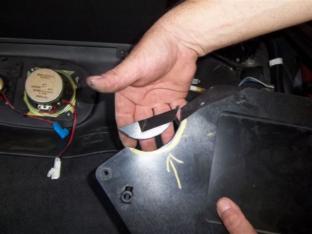
Fits like socks on a rooster. you gotta have a little country in-ya to get that one LOL.
Chris is worming up the 200 MPH MAGNUM FORCE water line rated at well over 2000 RWHP
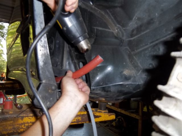
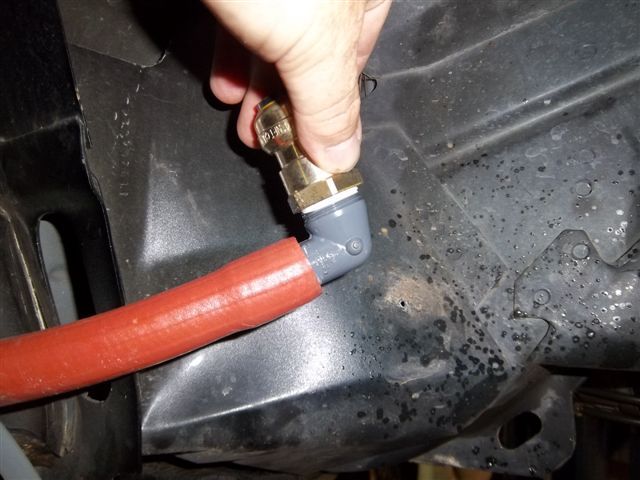
A little MAGNUM LUBE 200 and the fitting pushes right in
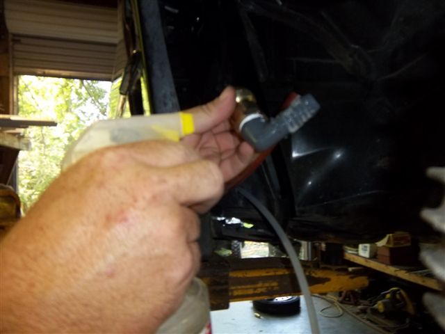
You can see the MAGNUM FORCE 225 fittings are larger that the hose ID,
this combination is rated north of 10,000 PSI @ over 2000 RWHP
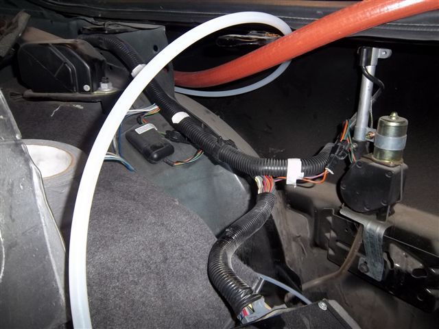
Passengerside
Drivers side water line and pump harness
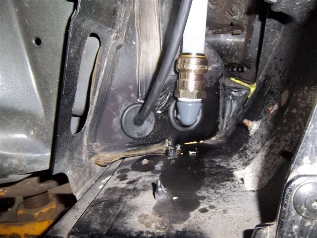
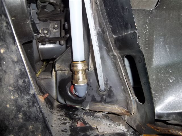
7/8" MAGNUM FORCE 210 high density Teflon tubing carry's the water inside the inner fender.
The splash shield with cover the 225 for the stealthy sleeper look
and wiring harness for the intercooler pump are run through the rocker panels.
First we start by cutting holes.
This is the passenger side, the small hole is for the coolant recovery line.
Notice the rubber grommet.
We feed a electricians fish tape from front to rear to pull the hoses through the rocker panel.
Chris feeds the hose over the wheel tub into the rocker panel as someone pulls on the fish tap.
You can see were the hose enters the rocker panel.
There is a piece of foam covering a hole in the top of the rocker panel on both sides.
The hole is about the size of an egg, perfect for water lines and a pump harness.
Dan's car is equip with the Monsoon sound system. The amp bracket needs a little notching.
You can see were Chris marked it for the cut.
Fits like socks on a rooster. you gotta have a little country in-ya to get that one LOL.
Chris is worming up the 200 MPH MAGNUM FORCE water line rated at well over 2000 RWHP
A little MAGNUM LUBE 200 and the fitting pushes right in
You can see the MAGNUM FORCE 225 fittings are larger that the hose ID,
this combination is rated north of 10,000 PSI @ over 2000 RWHP
Passengerside
Drivers side water line and pump harness
7/8" MAGNUM FORCE 210 high density Teflon tubing carry's the water inside the inner fender.
The splash shield with cover the 225 for the stealthy sleeper look
Last edited by ModularTurbo; Jun 8, 2012 at 08:12 PM.
LS1 Tech Stories
The Best V8 Stories One Small Block at Time

Amazing '71 Camaro Restomod Is Modern Muscle Car Under the Skin
Verdad Gallardo
6 Common C5 Corvette Failures and What's Involved In Repairing Them
Pouria Savadkouei
Retro Modern Bandit Pontiac Trans AM Comes With Burt Reynolds' Autograph
Verdad Gallardo
Top 10 Greatest Cadillac V Series Performance Models Ever, Ranked
Pouria Savadkouei
Top 10 Most Powerful Chevy Trucks Ever Made!

Hennessey's New Supercharged Silverado ZR2 Has 700 HP
Verdad Gallardo
Coachbuilt N2A Anteros Is an LS2-Powered C6 Corvette In Italian Clothes
Verdad Gallardo
Awesome K5 Blazer Restomod Comes With C7 Corvette Power
Verdad Gallardo
10 Camaros You Should Never Buy
Staging Lane
Joined: Dec 2011
Posts: 56
Likes: 0
From: Stevens Point, WI
I figured there be something under the seat lol that isn't mine though, the $100.00 bill is lol. The way you ran that water lines is awesome i would of never thought of that. When you get to the egr canister crap in the bumper just chuck that out who needs egr anyways lol. loving the pics guys keep em' coming.
Thread Starter
FormerVendor
iTrader: (14)
Joined: Jun 2008
Posts: 1,765
Likes: 2
From: Homestead, FL
The coolant recovery tank/battery box needs to be modified for air filter clearance.
Chris marks the coolant recovery tank for the first cut. He cuts the tank off and does
a final trim.
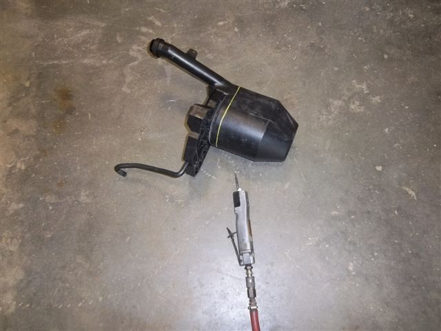
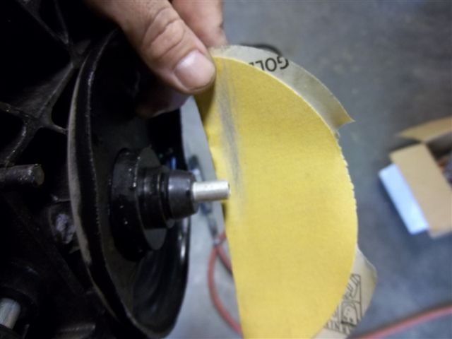
The filler neck gets cut off as well
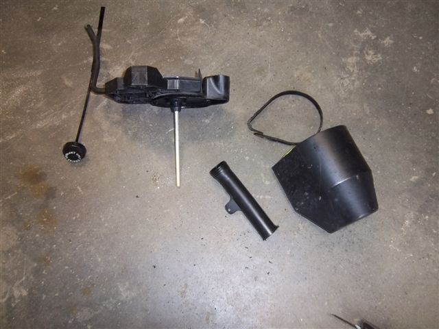
Next the dip tube gets cut to length
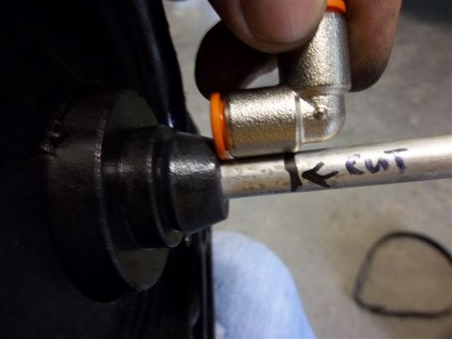
Chris used a tubing cutter to cut the dip tube. The edge of the dip tube is dressed
up with sand paper to prevent it from cutting the O-ring in the push on fitting
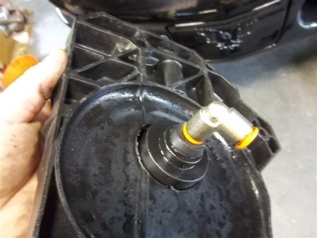
The push on fitting in installed. Remember the smaller 3/8 tubing we pulled
threw the rocker panel on the passenger side? it hooks up the this fitting.
The coolant recovery tank in rear of the car now
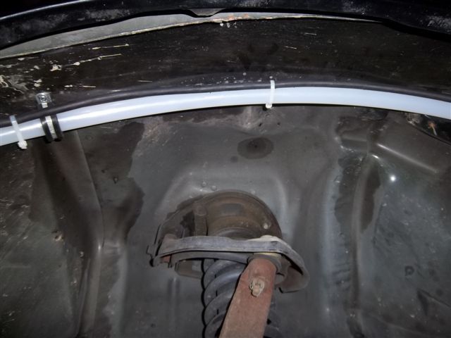
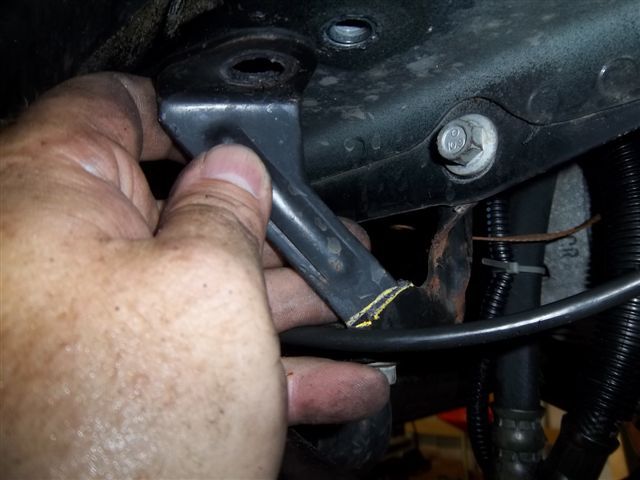
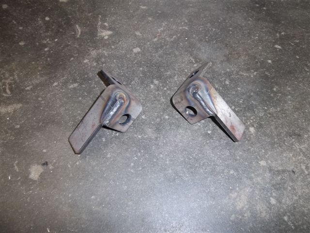
This the drivers side sway bar bracket marked for a cut.
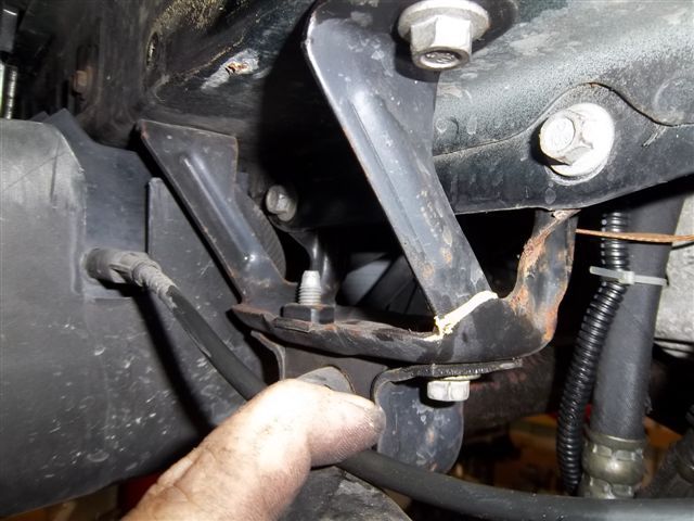
Here the cut has been made. A new bracket that Chris engineered will replace
the stock one
Here are the 2 replacement brackets, LH and RH
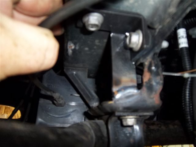
Here is the drivers side bracket welded in place. It provides clearance for the
charge air pipes so they can be tucked in tight enough so the tire don't hit under
lock to lock turning
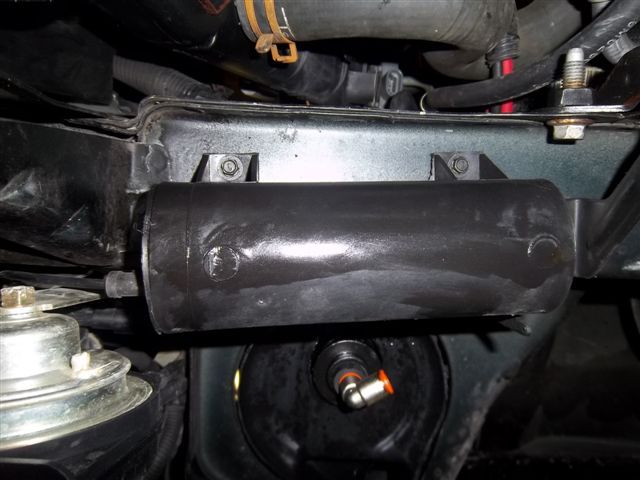
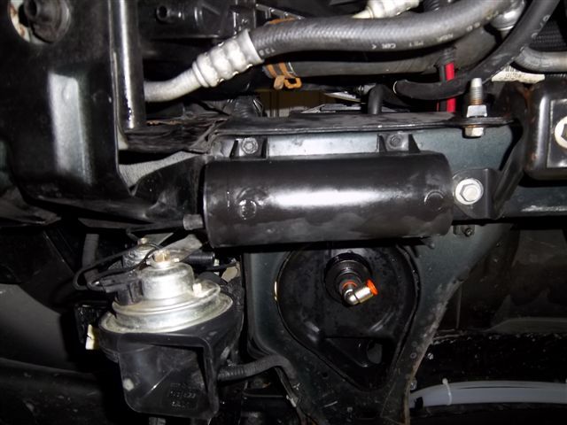
The plastic canister is a vacuum reservoir, we don't need to use it but we opted
to use it because it is a factory component and we love leaving cars as stock as possible.
The following pics show how we relocated it. It needs to be moved to make room for the
passenger side charge air pipe
Chris marks the coolant recovery tank for the first cut. He cuts the tank off and does
a final trim.
The filler neck gets cut off as well
Next the dip tube gets cut to length
Chris used a tubing cutter to cut the dip tube. The edge of the dip tube is dressed
up with sand paper to prevent it from cutting the O-ring in the push on fitting
The push on fitting in installed. Remember the smaller 3/8 tubing we pulled
threw the rocker panel on the passenger side? it hooks up the this fitting.
The coolant recovery tank in rear of the car now
This the drivers side sway bar bracket marked for a cut.
Here the cut has been made. A new bracket that Chris engineered will replace
the stock one
Here are the 2 replacement brackets, LH and RH
Here is the drivers side bracket welded in place. It provides clearance for the
charge air pipes so they can be tucked in tight enough so the tire don't hit under
lock to lock turning
The plastic canister is a vacuum reservoir, we don't need to use it but we opted
to use it because it is a factory component and we love leaving cars as stock as possible.
The following pics show how we relocated it. It needs to be moved to make room for the
passenger side charge air pipe
Last edited by ModularTurbo; Jun 9, 2012 at 08:59 PM.

FormerVendor
Joined: Feb 2011
Posts: 547
Likes: 1
I can not take credit for that idea.
Jesse and Ryon from Alexis body shop Slidell LA showed me that hole in the rocker
panel and suggested I consider running the water lines that way on the next one.
They helped me with the install on there little brothers car.
Those guys know there F-body's inside and out.
Jesse and Ryon from Alexis body shop Slidell LA showed me that hole in the rocker
panel and suggested I consider running the water lines that way on the next one.
They helped me with the install on there little brothers car.
Those guys know there F-body's inside and out.


TECH Fanatic
Joined: Nov 2001
Posts: 1,027
Likes: 2
From: KS
This ^^^ is a fact. Problem is there is alot of stuff on the board that people use or do that I would either throw away or not consider using and that junk will get 52,000 views. And the stuff in this thread that shows some real thought will get over looked. 
