


High amperage control cuircut relay?
Thread Starter
TECH Enthusiast
iTrader: (4)
Joined: Dec 2005
Posts: 612
Likes: 0
From: Nashville, TN
Anyone know if this would work for a early warning system for my 9-10amp electric water pump and each of my 5.8 amp fuel pumps? the continuous duty control side looks to be problematic for regular parts store relays?
Thread Starter
TECH Enthusiast
iTrader: (4)
Joined: Dec 2005
Posts: 612
Likes: 0
From: Nashville, TN
No what I'm talking about is the pump side of the relay. They don't normally have the ability to handle continuous higher load. The switching side is supose to be just a switched contact between positive and ground not to carry a load...the led portion is fine they aren't any load...

TECH Addict
Joined: Jun 2009
Posts: 2,012
Likes: 0
From: Tulsa, OK
You can get high current relays...just as a thought, how about a Ford style starter solenoid? Also, see http://www.allelectronics.com/ or http://www.mouser.com/
You can get high current relays...just as a thought, how about a Ford style starter solenoid? Also, see http://www.allelectronics.com/ or http://www.mouser.com/
Trending Topics
LS1 Tech Stories
The Best V8 Stories One Small Block at Time

6 Common C5 Corvette Failures and What's Involved In Repairing Them
Pouria Savadkouei
Retro Modern Bandit Pontiac Trans AM Comes With Burt Reynolds' Autograph
Verdad Gallardo
Top 10 Greatest Cadillac V Series Performance Models Ever, Ranked
Pouria Savadkouei
Top 10 Most Powerful Chevy Trucks Ever Made!

Hennessey's New Supercharged Silverado ZR2 Has 700 HP
Verdad Gallardo
Coachbuilt N2A Anteros Is an LS2-Powered C6 Corvette In Italian Clothes
Verdad Gallardo
Awesome K5 Blazer Restomod Comes With C7 Corvette Power
Verdad Gallardo
10 Camaros You Should Never Buy

10 LS Engine Myths That Refuse to Die
Verdad Gallardo
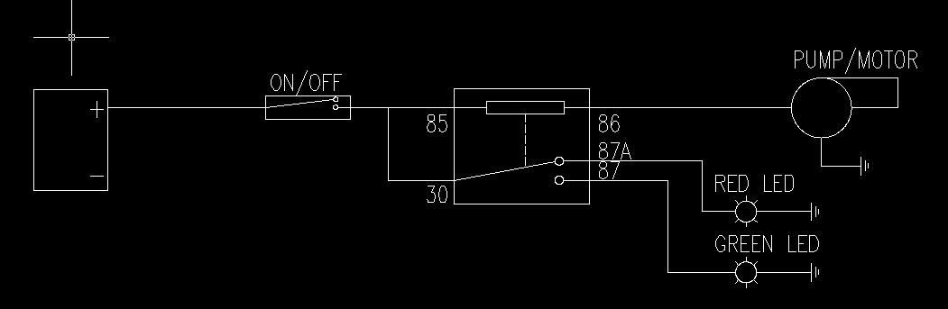
the first schematic by is wrong having the on/off switch control the current to both the high and low side of the relay. that defeats the purpose of the relay. what you want to do is have a feed from battery positive such as from the underhood fuse block directly to the high current side of the relay which would be pin 85 in the original schematic, and it would be a good idea to put a 15 amp fuse (based on the current draw of the pump or whatever the load on the high current side of relay) on this circuit between the source and the relay.
for the low current switching side of the relay, pin 30 in original schematic, you want to connect to your on/off switch however you want to do that- either with a manual switch in the cabin fed from a +12v source like cigarette lighter or tap off an ignition wire from the fuse block that only gets power when the ignition key is in the run position
in the original schematic with the 5 prong relay, I believe that's correct from what i can remember in that when your on/off switch is off, pin 87a, the center prong, is hot so you can use that to tell when your circuit is switched off. And when your switch in on then it puts pin 87 hot but you don't want to tap off that for the green led. You want the green led tapped off pin 86, the high current side feeding the pump. You want the green led tapped in parallel off pin 86 and this will tell when your on/off switch is on, and the pump is getting voltage. Pin 87 needs to go directly to ground for the relay to work reliably otherwise enough current may not pass through the coil of the relay and make it switch the high current side.
Now here's the big thing, all this only let's you know whether you have your pump, or whatever the load is on the circuit, switched on or off. On will have green led lit, off will have red led it. It only tells you if the pump is getting power and whether the relay is working. It does not tell you if the pump is failed or actually running!
you can get the relay rated for 20A and higher at radioshack, it goes by automotive relay and is like $6. I've been getting most of my stuff from allelectronics.com. The 5 prong relay I think you want is this, not sure if radioshack carries them
http://www.allelectronics.com/make-a...-RELAY//1.html
Any solid state relay like this will handle continuous duty of your pump just fine provided you know the rating of the load, if you're sure the pump only pulls 10A then any 20A or higher relay will be fine. If it's 15A or above then I would get a 30A or higher relay.
for LED's, just get 12v rated led's from radioshack, they usually have them in store. No need to mess around with resistors.
http://www.radioshack.com/product/in...ductId=2062569
Last edited by 1 FMF; Aug 24, 2010 at 08:07 AM.
Thread Starter
TECH Enthusiast
iTrader: (4)
Joined: Dec 2005
Posts: 612
Likes: 0
From: Nashville, TN
the first schematic by is wrong having the on/off switch control the current to both the high and low side of the relay. that defeats the purpose of the relay. what you want to do is have a feed from battery positive such as from the underhood fuse block directly to the high current side of the relay which would be pin 85 in the original schematic, and it would be a good idea to put a 15 amp fuse (based on the current draw of the pump or whatever the load on the high current side of relay) on this circuit between the source and the relay.
for the low current switching side of the relay, pin 30 in original schematic, you want to connect to your on/off switch however you want to do that- either with a manual switch in the cabin fed from a +12v source like cigarette lighter or tap off an ignition wire from the fuse block that only gets power when the ignition key is in the run position
in the original schematic with the 5 prong relay, I believe that's correct from what i can remember in that when your on/off switch is off, pin 87a, the center prong, is hot so you can use that to tell when your circuit is switched off. And when your switch in on then it puts pin 87 hot but you don't want to tap off that for the green led. You want the green led tapped off pin 86, the high current side feeding the pump. You want the green led tapped in parallel off pin 86 and this will tell when your on/off switch is on, and the pump is getting voltage. Pin 87 needs to go directly to ground for the relay to work reliably otherwise enough current may not pass through the coil of the relay and make it switch the high current side.
Now here's the big thing, all this only let's you know whether you have your pump, or whatever the load is on the circuit, switched on or off. On will have green led lit, off will have red led it. It only tells you if the pump is getting power and whether the relay is working. It does not tell you if the pump is failed or actually running!
you can get the relay rated for 20A and higher at radioshack, it goes by automotive relay and is like $6. I've been getting most of my stuff from allelectronics.com. The 5 prong relay I think you want is this, not sure if radioshack carries them
http://www.allelectronics.com/make-a...-RELAY//1.html
Any solid state relay like this will handle continuous duty of your pump just fine provided you know the rating of the load, if you're sure the pump only pulls 10A then any 20A or higher relay will be fine. If it's 15A or above then I would get a 30A or higher relay.
for LED's, just get 12v rated led's from radioshack, they usually have them in store. No need to mess around with resistors.
http://www.radioshack.com/product/in...ductId=2062569
I think you missed something here and again your thinking im using the relay in the typical way. The low amperage CONTROL side of the relay uses pins 85 and 86, typically you just ground 86 and have 85 as your switched 12V source. Now since im going through a pump first BEFORE it sees the ground the control side of the relay will ONLY energize if it sees the ground on the other side of the pump. If the pumps electric motor fails typically the positive side never gets to a ground therefore the relay cannot energize and instead of transferring power from pole 30 to 87 triggering the green light it transfers it to 87A lighting the red light since the 30 to 87A route is closed when the control side of the relay is NOT energized. you absolutely need switched 12V power on both the 30 and the 85 poles.
Now the poblem is the CONTROL side of the relay is not ment for any amp draw. Its wound with really tiny wire so the added amperage from the electric motor tends to burn out the control side. you could buy a 100 amp relay and it still wouldnt last since relays are rated at the switch side (between poles 30 and 87/87A) and NOT the control side.
Sooo to fix the control side wiring problem im going to try cutting out the coil windings in the relay and replacing it with thicker wire to carry the amp draw of the electric motor. Since theres alot more amps in this line I wont need nearly as many windings to create the magnetic field to close the relay.

Joined: Aug 2007
Posts: 24,241
Likes: 89
From: Turnin' Wrenches Infractions: 005
I think you missed something here and again your thinking im using the relay in the typical way. The low amperage CONTROL side of the relay uses pins 85 and 86, typically you just ground 86 and have 85 as your switched 12V source. Now since im going through a pump first BEFORE it sees the ground the control side of the relay will ONLY energize if it sees the ground on the other side of the pump. If the pumps electric motor fails typically the positive side never gets to a ground therefore the relay cannot energize and instead of transferring power from pole 30 to 87 triggering the green light it transfers it to 87A lighting the red light since the 30 to 87A route is closed when the control side of the relay is NOT energized. you absolutely need switched 12V power on both the 30 and the 85 poles.
Now the poblem is the CONTROL side of the relay is not ment for any amp draw. Its wound with really tiny wire so the added amperage from the electric motor tends to burn out the control side. you could buy a 100 amp relay and it still wouldnt last since relays are rated at the switch side (between poles 30 and 87/87A) and NOT the control side.
Sooo to fix the control side wiring problem im going to try cutting out the coil windings in the relay and replacing it with thicker wire to carry the amp draw of the electric motor. Since theres alot more amps in this line I wont need nearly as many windings to create the magnetic field to close the relay.
Thread Starter
TECH Enthusiast
iTrader: (4)
Joined: Dec 2005
Posts: 612
Likes: 0
From: Nashville, TN
Joined: Aug 2007
Posts: 24,241
Likes: 89
From: Turnin' Wrenches Infractions: 005
Im speaking of the relay, in your diagram you have the activation side of the relay flowing current to the "pump", which uses current. If, when you hooked up a relay, it didnt have a resistance on the activation side, it be like a short circuit flowing tons of current. However, since when you hook it up it flows very little current, leads me to believe it has a high internal resistance, which would not work when specifically trying to flow current through it. However, I have never really looked inside a relay so these are just thoughts.
ok i see what you are doing now with the original diagram.
the problem then is the control side of the relay, the coil, are usually 30-ohms and greater. The link i posted has an 88-ohm coil, and other radioshack relays have around 300-ohm coils. So if you know V=IR, this is a simple series circuit. I'll use 13volt as battery voltage for the math,
based on a 10 amp draw, the pump has about 1.3 ohms of resistance. Using 88-ohms for the coil, total series circuit resistance is 89.3 ohms: I=V/R = 13v/89.3ohms = 0.146 amps current in the circuit. Therefore the voltage drop after the 88-ohm relay coil, using V=IR, is 0.146A * 88ohm = 12.8 volts.
So by using a relay with an 88 ohm coil before the pump, the pump will only see 0.2 volts and 0.146 amps of current. The pump will never work.
Although the pump is supposed to draw 10 amps (based on a 12-14 volt supply voltage) it will not if you put any kind of other resistance in the circuit, which is a series circuit, because that will decrease the amount of current in the circuit which in turn will undervolt the pump and prevent it from working.
What you need to do is wire things in parallel, which will allow full voltage and current to reach the pump. The easiest and I think the only thing you can do is use one (green) led that i listed and connect its red wire to the wire going to the pump, black led wire to ground, this will illuminate the led whenever power is going to the pump, but it will not tell you if the pump is running.
You said you want a warning system which i think means you want to know if your pump is not running when it is getting power. Unfortunately there's no way to do this unless there is a tachometer output signal coming off the motor or it's a motor with some circuitly that has a tap specifically for that. If it's just a motor with a red and black wire coming off it, there is no way to tell electrically if the motor is spinning. At best if the motor were to crap out and then it became an open circuit between its red and black wire you may be able to rig something up with transistors to detect that open circuit.
Joined: Aug 2007
Posts: 24,241
Likes: 89
From: Turnin' Wrenches Infractions: 005


Thread Starter
TECH Enthusiast
iTrader: (4)
Joined: Dec 2005
Posts: 612
Likes: 0
From: Nashville, TN
Where is this "other" resistance coming from!? the control side is just a coil of wire! theres almost no resistance...... I give up trying to explain this lol I think you guys are thinking about this WAY to hard....Aslong as I have enough loops in the wire to create a magnetic field the relay is going to close the the circuit between 30 and 87.... Ive had two Electrical engineers work this out and as long as the wire im using to make my coil can carry the amperage it'll work like a charm.
Where is this "other" resistance coming from!? the control side is just a coil of wire! theres almost no resistance...... I give up trying to explain this lol I think you guys are thinking about this WAY to hard....Aslong as I have enough loops in the wire to create a magnetic field the relay is going to close the the circuit between 30 and 87.... Ive had two Electrical engineers work this out and as long as the wire im using to make my coil can carry the amperage it'll work like a charm.
i'll try to explain without typing out DC circuits 101,
your electric water pump, from an electrical perspective, and an inductive motor. without it running if you measured resistance through the motor's red & black wire it would measure 0 ohms (or very close to zero) because its solid copper wire around the armature and no resistance through the brushes to the armature. Or it's continuous wire in the stator if it's a brushless motor. Regardless, when you feed the motor enough power to make it work it generates a magnetic field (which is how electric motors work) and that induction results in an electrical resistance which is what limits current flow. It's DC current, so ohm's law V=IR applies, and when the motor is running it resembles around 1-2 ohms of resistance. Mathematically it has to otherwise if there was zero resistance there would be an unlimited current flow according to ohms law: V=IR; I=V/R; I = voltage / zero.
So hopefully you understand the electric motor in question has some resistance, and the fact it's rated at drawing 9-10 amps under a 12 volt (really 14.4 volt because that's what alternator outputs when engine is running) that means R = V/I = 14.4v / 10amp = 1.44 ohms, so 1-2 ohms. It's also a 144 watt motor

relays, the one your using, is a coil of wire which works in a similar manner. When you pass current through the wire, because it's wrapped around a piece of iron or ferrous material, it creates a magnet field which does the work, and that work shows up as resistance in the electrical circuit. The link i posted for the 5 prong relay, states an 88-ohm coil. You may find some relays with coils that have as low as 20 ohms but that still won't matter.
For arguments sake say you found a relay with a 1.0 ohm coil. You mentioned it's just a coil of wire with "almost" no resistance. Would you consider 1 ohm "almost" no resistance?
Your electric motor is 1-2 ohms but we'll say 1.0 to keep math simple. The relay if it were at 1 ohm in a series circuit is half the resistance of the motor, so for a 12.0 volt supply voltage there will be a 6.0 volt drop across the relay coil and only 6.0 volts going to the pump, the pump won't work. And because it's a series circuit total resistance is 2.0 ohms (1.0 for motor and 1.0 for relay coil) which means for a 12 volt supply, the current will be 6 amp. The motor will only be getting 6 amps at 6.0 volts, it won't work, it's rated at 9-10 amp at 12-14 volt. If the motor did happen to work at 6 volt, it would work poorly and because it's undervolted it would get hot and fail sooner.
here is a document about relays, written by Kevin R Sullivan, he's a professor

http://www.autoshop101.com/forms/hweb2.pdf
the problem is the way relays work, and you're trying to use one in a way that a relay isn't meant to be used and you're using it in a series circuit. For the relay to even work it must induce a resistance in order to do the work of moving the little switch inside to switch the high current side on, no different than the resistance created by the electric motor when it is doing work. You mention "enough loops in the wire to create a magnetic field"... enough loops around the ferrite core is what creates the resistance, and enough loops to make it work will simply cause a resistance that is too great for a series circuit.
For what you want to do, shitcan the relay at least for the led setup. You should be using a relay like it's intended to be used for powering the pump so you don't burn out your on/off switch, and the pump probably came with one for that reason. Simply wire the 12v led in parallel off the feed wire to the pump, that will tell you when the pump is powered which is all you would have been doing in the beginning. You're original circuit could not tell if the motor is actually running, simply forgo the 2nd [red] led lit to mean the pump isn't powered. If the one led isn't powered, it means the pump isn't on.
