


High Level Technical Information on Ignition Wires / Components

Thread Starter
FormerVendor
Joined: Jul 2008
Posts: 77
Likes: 0
DIELECTIC PROPERTIES OF A MATERIAL
For the next subject I thought I would share on the subject of dielectric strength of a material. This comes into play when trying to contain high voltage levels in a conductor, or in other words the insulators on the ignition wire.
A dielectric is an electrical insulator that can cause electric charges to shift in the insulating material causing an internal electric field which can effectively reduce the energy efficiency in the system.
Although the term "insulator" implies low electrical conduction, "dielectric" is typically used to describe materials with a high polarizability which cause electrical energy to be absorbed by the insulator.
Here are the dielectric constants of some materials
TEFLON 2.0 (insulator)
SILICONE RUBBER 3.2-9.8 (insulator)
*the higher the number the more suseptible it is to causing energy loss if used as an insulator.
Commonly the insulating layer of silicon can break down causing it to polarize causing it to drain the energy from the wire. This effect would cause the wire to loose energy as heat.
We could deal with this in several ways.
1) Just coat the spiral core with silicon rubber much like our competitors and take the losses created by the rubber silicon layer.
2) This option was tossed around during development along with option 3. Coat the spiral wire in a superior dielectric material to prevent losses from happening. Due to this NASA uses Teflon coated wire in satelites (note Teflon has a lower constant) to prevent this issue and create a superior low loss wire. This is because Teflon is superior to silicon and has better insulating properties from electricity. After much debate we went with option 3 because option 3 also allows conduction and perfect terminations that won't degrade over time.
3) We use a material that behaves very much like a metal to coat the conductor, graphite / carbon. Because graphite has a tendency to effectively conduct energy, unlike silicon, it allows conduction of energy that wishes to penetrate it rather then retain it. So if electron movement does happen in this layer it is minimal, as the bulk of energy will run through the spiral core, and electrical losses are kept to a minimum. This is another primary reason why we use a graphite / carbon based protective layer over the spiral core. Because graphite has a tendency to behave very much like a metal, due to the carbon molecules arranging themselves into a lattice structure, if electrical energy flows to the protective skin it allows the energy to flow to the spark plug rather then hold and waste it as heat much like silicon. The graphite layer also keeps large currents away from our protective high quality silicon layer and prevents the silicon from ever breaking down and causing energy loss in the wire.
Now we have a wire that can create perfect terminations that do not oxidise or deteriorate over time, have increased efficiency over competitor wire and long life span.
Last edited by WeaponX_Perf; Oct 15, 2011 at 02:49 PM.
On The Tree
Joined: Feb 2004
Posts: 111
Likes: 0
From: Graham, WA
Seeing as an ohmmeter will measure core resistance, and not outer boundary resistance (where the high voltage current actually travels, AROUND the core) its not really valid science. Interesting, yes, but that's about it when you look at how the coil energy actually travels along the wire.
0 ohm spark plugs are also fantasy. There HAS to be resistance. Maybe not 10,000 ohms, but certainly not 0.
0 ohm spark plugs are also fantasy. There HAS to be resistance. Maybe not 10,000 ohms, but certainly not 0.
Thread Starter
FormerVendor
Joined: Jul 2008
Posts: 77
Likes: 0
Seeing as an ohmmeter will measure core resistance, and not outer boundary resistance (where the high voltage current actually travels, AROUND the core) its not really valid science. Interesting, yes, but that's about it when you look at how the coil energy actually travels along the wire.
0 ohm spark plugs are also fantasy. There HAS to be resistance. Maybe not 10,000 ohms, but certainly not 0.
0 ohm spark plugs are also fantasy. There HAS to be resistance. Maybe not 10,000 ohms, but certainly not 0.
Also, if you want to get technical about our spark plugs, they actually measure between 0.2 - 0.4 ohms per plug, pretty much as close as your going to get in the circuit to 0 ohms.
On The Tree
Joined: Feb 2004
Posts: 111
Likes: 0
From: Graham, WA
This type of thinking has been passed on for decades and unfortunately holds little to zero validity in regards to secondary output on an ignition system (where ignition wire is). What I believe you are referring to is skin effect where current likes to travel on the boundary layer. Unfortunately skin effect does not apply to DC ignition currents where current only flows in one direction, ie ignition coil outputs. It is only when we start talking about household or industrial AC power that skin effect becomes a concern or when frequencies in a system are excessive (ie RF signal generation in CB radios that have A/C frequencies in the order of gHz range). In an ignition, we use DC current at low frequency so skin effect doesn't really apply since current is only in the forward direction (DC not AC).
Also, if you want to get technical about our spark plugs, they actually measure between 0.2 - 0.4 ohms per plug, pretty much as close as your going to get in the circuit to 0 ohms.
Also, if you want to get technical about our spark plugs, they actually measure between 0.2 - 0.4 ohms per plug, pretty much as close as your going to get in the circuit to 0 ohms.
Kind of like how you can't drive a coil with a battery (solid dc), or a 120v AC line (solid DC), but you can drive one with a dimmer switch (pulsed DC/AC).
And if I wanted to get technical about your spark plugs, 0.4 ohms is an infinite difference to 0 ohms. Get it?
Thread Starter
FormerVendor
Joined: Jul 2008
Posts: 77
Likes: 0
Except that the DC in question here isn't a solid state current, as a typical HEI coil cannot sustain that kind of discharge. In a pulsed DC circuit (as opposed to a solid state), the skin effect does indeed apply.
Kind of like how you can't drive a coil with a battery (solid dc), or a 120v AC line (solid DC), but you can drive one with a dimmer switch (pulsed DC/AC).
And if I wanted to get technical about your spark plugs, 0.4 ohms is an infinite difference to 0 ohms. Get it?
Kind of like how you can't drive a coil with a battery (solid dc), or a 120v AC line (solid DC), but you can drive one with a dimmer switch (pulsed DC/AC).
And if I wanted to get technical about your spark plugs, 0.4 ohms is an infinite difference to 0 ohms. Get it?
AC SINE WAVE BELOW
Notice the power actually passes the 0 volt threshold and then changes polarity. In a DC circuit it never crosses 0 volts, just like in an ignition coil output. It doesn't need to be sustained to be considered a DC voltage. For example, if I turned on and off a DC source, it is still DC and I don't introduce AC by doing that. The only thing that matters is that the current isn't ALTERNATING CURRENT (AC POWER) between a positive and negative value. This is how skin effect happens, due to the changes in polarity.
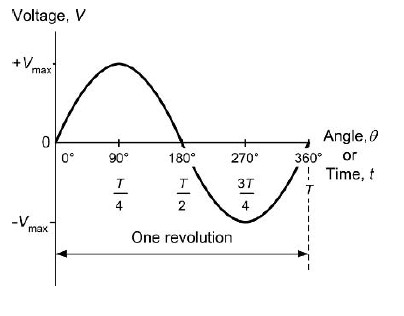
Even though the output is pulsed in an ignition output the current only moves in the forward direction and is a pure DC signal and consistent polarity so unfortunately skin effect doesn't apply.
We can argue symantics about a 0.4 ohm difference, however I have to disagree with your statement. An infinite difference in resistance, plainly, is having infinite resistance, which means that the circuit wouldn't even be connected. In power electronics like ignition systems 0.4 ohms isn't even worth a mention. As stated previously a 10,000ohm reduction in resistance creates a few engine hp. 0.4ohms wouldn't make the least difference and, we don't engineer based on resistance values alone. It is only a small part of the overall equation.
The idea of our spark plug and wire combo is to eliminate 11,000 ohms of resistance to recover some energy lost and gain some engine hp. It wouldn't make any difference if I said 10,999.6 ohms, in dynos or testing, the results would be the same.
Last edited by WeaponX_Perf; Oct 16, 2011 at 05:52 PM.
Thread Starter
FormerVendor
Joined: Jul 2008
Posts: 77
Likes: 0
For a better and easier understanding of the effects of poor dielectric properties of an insulator, many people have experienced and seen ignition wires glow, which is called corona effect.
If someone sees their ignition wires glowing at night, this is an initial sign of the corona effect. The presence of corona can reduce the reliability of a system by degrading insulation. Corona is actually a low energy process, meaning it is actually pulling energy from the spark events and into the insulator to create the glow effect. Over long periods of time, it can substantially degrade insulators, causing a system to fail due to dielectric breakdown.
Corona is a phenomenon that has the capability for degrading insulators, and causing systems to fail. Typically most manufacturer wires directly contact the silicon insulating layer of the ignition wire potentially causing corona effect and degrading the wires insulating effect over time.
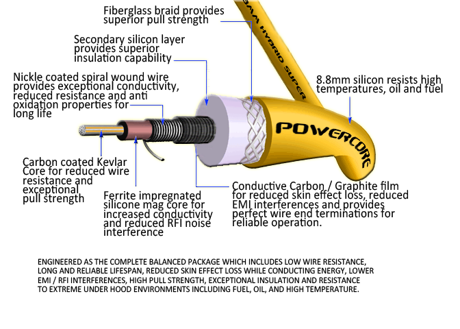
WeaponX PowerCore 8.8mm wire uses protective methods, such as our carbon / graphite coating to isolate and reduce surface current contact on the insulator and increase wire lifespan and reliability over competitor wires. Also, the thick 8.8mm wire ensures reliable insulation capability in extremely high voltage situations.
OTHER IGNITION WIRE ENHANCEMENTS
As with most other wires WeaponX uses a Teflon inner insulator for pull strength as well as glass braiding on the secondary silicon layer. However, we also add a conductive coating to the inner teflon core. This reduces dielectric losses when electricity is conducting in the core and increases conductivity and performance of the wire vs competitor solutions.
WeaponX also adds a Ferrous inner core, which is a magnetic permeable material as well as conductive. This increases the CORE energy recovery effect of the ignition wire and also allows for conduction of currents through the center of the wire. What it also does is enhance the spiral wires ability to contain and eliminate interference energy surrounding the wire and passing through the wire.
In summary, as seen, our goal is to reduce unwanted resistances to an absolute minimum but there is more then just resistance that comes into play when designing an ignition wire. Careful consideration to reducing interferences, insulation and dielectric properties as well as energy recovery, minimizing overall losses in the ignition wire and ensuring a long, reliable lifespan all play a vital role in a quality wire. Anyone can throw a conductor in a silicon insulator or a spiral wound wire around a rubber core and call it an ignition wire, but understanding the true inner workings and differences of the ignition wire is the key to knowledge and we wanted people to really understand why various components that added cost and complexity to the wire were used vs the standard inner workings of many competitor wires.
That summarizes most of the items in the ignition wire fairly well and why the various layers of components were introduced into the ignition wire. If anyone has any other questions or comments feel free to share your thoughts.
If someone sees their ignition wires glowing at night, this is an initial sign of the corona effect. The presence of corona can reduce the reliability of a system by degrading insulation. Corona is actually a low energy process, meaning it is actually pulling energy from the spark events and into the insulator to create the glow effect. Over long periods of time, it can substantially degrade insulators, causing a system to fail due to dielectric breakdown.
Corona is a phenomenon that has the capability for degrading insulators, and causing systems to fail. Typically most manufacturer wires directly contact the silicon insulating layer of the ignition wire potentially causing corona effect and degrading the wires insulating effect over time.
WeaponX PowerCore 8.8mm wire uses protective methods, such as our carbon / graphite coating to isolate and reduce surface current contact on the insulator and increase wire lifespan and reliability over competitor wires. Also, the thick 8.8mm wire ensures reliable insulation capability in extremely high voltage situations.
OTHER IGNITION WIRE ENHANCEMENTS
As with most other wires WeaponX uses a Teflon inner insulator for pull strength as well as glass braiding on the secondary silicon layer. However, we also add a conductive coating to the inner teflon core. This reduces dielectric losses when electricity is conducting in the core and increases conductivity and performance of the wire vs competitor solutions.
WeaponX also adds a Ferrous inner core, which is a magnetic permeable material as well as conductive. This increases the CORE energy recovery effect of the ignition wire and also allows for conduction of currents through the center of the wire. What it also does is enhance the spiral wires ability to contain and eliminate interference energy surrounding the wire and passing through the wire.
In summary, as seen, our goal is to reduce unwanted resistances to an absolute minimum but there is more then just resistance that comes into play when designing an ignition wire. Careful consideration to reducing interferences, insulation and dielectric properties as well as energy recovery, minimizing overall losses in the ignition wire and ensuring a long, reliable lifespan all play a vital role in a quality wire. Anyone can throw a conductor in a silicon insulator or a spiral wound wire around a rubber core and call it an ignition wire, but understanding the true inner workings and differences of the ignition wire is the key to knowledge and we wanted people to really understand why various components that added cost and complexity to the wire were used vs the standard inner workings of many competitor wires.
That summarizes most of the items in the ignition wire fairly well and why the various layers of components were introduced into the ignition wire. If anyone has any other questions or comments feel free to share your thoughts.
LS1 Tech Stories
The Best V8 Stories One Small Block at Time

Topdon ONE vs. Artidiag 800 BT2: Which is the Diagnostic Tablet For You?
Pouria Savadkouei
Gas Monkey Built a 6-Wheel Ferrari Testarossa With a Corvette LT4 Engine
Verdad Gallardo
7 Most Reliable High-Performance Engines GM Has Ever Built
Verdad Gallardo
Amazing '71 Camaro Restomod Is Modern Muscle Car Under the Skin
Verdad Gallardo
6 Common C5 Corvette Failures and What's Involved In Repairing Them
Pouria Savadkouei
Retro Modern Bandit Pontiac Trans AM Comes With Burt Reynolds' Autograph
Verdad Gallardo
Top 10 Greatest Cadillac V Series Performance Models Ever, Ranked
Pouria Savadkouei
Top 10 Most Powerful Chevy Trucks Ever Made!
