


Technical Information on Gen V LT1 combustion system

Thread Starter
Teching In
Joined: May 2013
Posts: 41
Likes: 0
Hi, I'm formally a lurker who recently registered. I thought you guys would find this interesting. I had the opportunity to attend a public presentation on the Gen V combustion system back in April. If I could summarize the basic concept of the combustion sytem, it would be this: They took the Gen IV combustion chamber, reversed the position of the valves, and made the intake port focused a little more on mixture motion and a little less on intake flow.
Here's a basic comparison of the WOT power and torque curves for the LS3 and Gen V LT1:
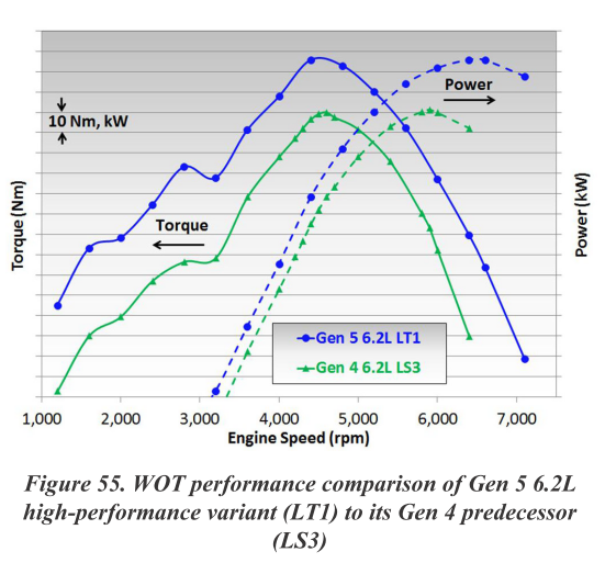
You can see a broader torque curve across the board and more power at higher revolutions.
Here are some basic specs:

Now let's compare the basic designs. Here's the Design A, basically a tweaked Gen IV layout:

Here's Design D, the architecture they ended up with. Notice the change in valve angle and reversed position of the intake and exhaust valves:

Here's a basic comparison of the WOT power and torque curves for the LS3 and Gen V LT1:
You can see a broader torque curve across the board and more power at higher revolutions.
Here are some basic specs:
Now let's compare the basic designs. Here's the Design A, basically a tweaked Gen IV layout:
Here's Design D, the architecture they ended up with. Notice the change in valve angle and reversed position of the intake and exhaust valves:
Thread Starter
Teching In
Joined: May 2013
Posts: 41
Likes: 0
In intake port design, a tradeoff exists between flow capability and mixing motion (turbulence). One of the key issues was figuring out the tradeoff between the two. This is extremely important in direct injected engines If flow is too low, the engine won't meet its performance targets. If mixture motion is sacrificed too much for flow, combustion performance will degrade. The engine will knock, have emission problems, and combustion could be unstable.
You can see the tradeoff illustrated in this chart:

After deciding to add more mixing motion, the intake port has to be optimized for the amount of swirl, tumble, and cross tumble.

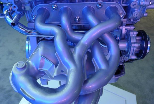
The Gen V is the only wedge-type combustion chamber going into production with direct injection. Its requirements are unique compared to typical 4 valve overhead cam engines. It required a certain amount of swirl motion to keep the flame from drifting into the edge of the combustion chamber. 4 valve engines with pentroof combustion chambers usually rely on high tumble with pretty limited swirl for direct injected applications. Ultimately, creating the proper motion required reversing the intake and exhaust valve positions. This also changed the shape of the intake manifold:

So there you have it: more mixture motion including a little bit of swirl, and some packaging changes ultimately resulted in a higher performing engine family with good fuel economy.
You can see the tradeoff illustrated in this chart:
After deciding to add more mixing motion, the intake port has to be optimized for the amount of swirl, tumble, and cross tumble.
The Gen V is the only wedge-type combustion chamber going into production with direct injection. Its requirements are unique compared to typical 4 valve overhead cam engines. It required a certain amount of swirl motion to keep the flame from drifting into the edge of the combustion chamber. 4 valve engines with pentroof combustion chambers usually rely on high tumble with pretty limited swirl for direct injected applications. Ultimately, creating the proper motion required reversing the intake and exhaust valve positions. This also changed the shape of the intake manifold:
So there you have it: more mixture motion including a little bit of swirl, and some packaging changes ultimately resulted in a higher performing engine family with good fuel economy.

Teching In
Joined: Dec 2010
Posts: 16
Likes: 0
From: Santa Barbara, CA
Did you make these documents? Or are they sourced from GM?
I think I noticed an error:
This is mislabeled? The bottom images are gen 4. Right?
Also, are you saying this is what the LT1 exhaust port looks like:
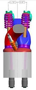
With the exhaust crossing over the spark plug??? Why would they do this? Couldn't they re-angle the plug?
I think I noticed an error:
This is mislabeled? The bottom images are gen 4. Right?
Also, are you saying this is what the LT1 exhaust port looks like:

With the exhaust crossing over the spark plug??? Why would they do this? Couldn't they re-angle the plug?
Thread Starter
Teching In
Joined: May 2013
Posts: 41
Likes: 0
They're sourced from a public presentation and paper by GM engineers. The paper is 32 pages long and highly technical... it's not something most people would be able to get through.
I didn't make these images, but I do know that the angle of the intake manifold runners are more straight due to the redesigned intake ports. Based on that, it's not likely that these are mislabeled, even though they may be a bit misleading due to the fact that they are CAD images and not photographs. I've seen the display models of the engine in person, but I can't say I have a good mental image of the intake runners.
Yes, the exhaust ports are S-shaped due to packaging and partly for turbulence. They do flow well though according to their studies.

They did investigate different plug locations. Having the plug closer to the center of the combustion chamber (compared to the Gen IV) was a really big deal due to the nature of flame propagation in a direct injected engine with this style of combustion chamber.

I think I noticed an error:
This is mislabeled? The bottom images are gen 4. Right?
This is mislabeled? The bottom images are gen 4. Right?
Also, are you saying this is what the LT1 exhaust port looks like:

With the exhaust crossing over the spark plug??? Why would they do this? Couldn't they re-angle the plug?
With the exhaust crossing over the spark plug??? Why would they do this? Couldn't they re-angle the plug?
They did investigate different plug locations. Having the plug closer to the center of the combustion chamber (compared to the Gen IV) was a really big deal due to the nature of flame propagation in a direct injected engine with this style of combustion chamber.
Teching In
Joined: Dec 2010
Posts: 16
Likes: 0
From: Santa Barbara, CA
I am an engineer and I find this stuff very interesting.
Would you mind posting the entire 32 page document? Or pointing me to a site that is hosting it already?
Thanks so much, I'm sure these will be useful to many tuners down the road.
Would you mind posting the entire 32 page document? Or pointing me to a site that is hosting it already?
Thanks so much, I'm sure these will be useful to many tuners down the road.
Last edited by ls1evan; May 29, 2013 at 07:32 PM.
Thread Starter
Teching In
Joined: May 2013
Posts: 41
Likes: 0
Trending Topics
LS1 Tech Stories
The Best V8 Stories One Small Block at Time

Topdon ONE vs. Artidiag 800 BT2: Which is the Diagnostic Tablet For You?
Pouria Savadkouei
Gas Monkey Built a 6-Wheel Ferrari Testarossa With a Corvette LT4 Engine
Verdad Gallardo
7 Most Reliable High-Performance Engines GM Has Ever Built
Verdad Gallardo
Amazing '71 Camaro Restomod Is Modern Muscle Car Under the Skin
Verdad Gallardo
6 Common C5 Corvette Failures and What's Involved In Repairing Them
Pouria Savadkouei
Retro Modern Bandit Pontiac Trans AM Comes With Burt Reynolds' Autograph
Verdad Gallardo
Top 10 Greatest Cadillac V Series Performance Models Ever, Ranked
Pouria Savadkouei
Top 10 Most Powerful Chevy Trucks Ever Made!

Hennessey's New Supercharged Silverado ZR2 Has 700 HP
Verdad Gallardo


 of these blocks start to prove themselves

On The Tree

Joined: Jan 2008
Posts: 109
Likes: 6
From: Where you least expect me
Turbo DI Ecotec engines make 260 HP from 2.0 liters.
Same specific output from a 6.2 would be 806 HP. With the DI, turbo lag is a distant memory.
When the C6 ZO6 came out, Ferrari had the 430 with 485 HP.
Now they have the 458 with direct injection and 560 HP. Anyone taking bets regarding what the next ZO6 will make?
I'm surprised that they weren't able to get the packaging they wanted without splaying the valves. I wonder if they could achieve the swirl without moving the valves, but then couldn't get enough water around the chambers.
It's also interesting to note that one valve transverse angle ends up .1 degree off the other one (hard to tell which is which).
Mixture motion is critical to DI performance, as noted... I'm not sure I'd want any of the first or even second generation aftermarket ports for this engine.
Also, there's a "dimple" in the upper corner of the Design D intake port. The corresponding area of the Design A port isn't visible, but I assume it's not there in Design A.
Thread Starter
Teching In
Joined: May 2013
Posts: 41
Likes: 0
On a V8 with the typical firing order (90 degree, 180, and 270 crank angle degrees between pulses) you need inboard exhaust manifolds to achieve the spool and torque for turbos. Basically, two twin scroll turbos--the same that Audi and BMW are doing on their V8's with inboard exhaust manifolds.
Otherwise without dividing the exhaust pulses you get a lot of exhaust gas interference in certain cylinders. It limits the ability to do scavenging. Other option is change the exhaust valve duration, like Porsche (with their weird exhaust cams on the twin turbo V8) and VW do (with the Audi Valvelift system) to affect the blowdown pulse timing.
And the cam phaser on the Gen V can't control overlap like the cam-in-cam design used by the Schaeffler group and Chrysler for pushrod applications. That also limits the ability to do scavenging. Look at the cam phasing used in basically every DOHC turbo DI engine--bigtime overlap at low speeds from cam phasing, like over 100 degrees sometimes.
See this paper published by Ford engineers https://docs.google.com/file/d/0B_jE...it?usp=sharing
Last edited by arghx7; Aug 27, 2013 at 08:13 PM.
On The Tree
Joined: Jan 2008
Posts: 109
Likes: 6
From: Where you least expect me
Exhaust in the V is just a convenient way to package 180 degree collectors (And turbos themselves for that matter).
GM's very good at designing the engine such that it can work very well with one cam profile. That comes from spending their development dollars on the "intangibles" like the CFD for port and chamber design that we're seeing here.
I've read elsewhere that DI can deliberately allow fuel to go out the exhaust because it can perform and anti-lag function. I'm not sure how significant this is or even if it can be done on an emissions-legal calibration.
Thread Starter
Teching In
Joined: May 2013
Posts: 41
Likes: 0

You can see in the twin-twinscroll arrangement, the cross-bank pairing of cylinders sets an even spacing of exhaust pulses. It's like a 4 cylinder where #2 and #3 are paired, and #1 and #4 are paired, each to a respective scroll on the turbo.


In the above indicator diagrams (pressure-volume pumping loop) you can see the spike in the red loop. That's exhaust gas interference from running single scroll twin turbos with outboard manifolds (what we're used to LSx engines). The extra pumping work is basically wasted engine output (pumping and friction work reduce brake torque). The blue pumping loops show a relative reduction in exhaust gas interference and an associated decrease in residual gases. This improves knock limit and reduces pumping work. It's the exact design that BMW and Audi are using on production V8 twin turbo engines.
GM's very good at designing the engine such that it can work very well with one cam profile. That comes from spending their development dollars on the "intangibles" like the CFD for port and chamber design that we're seeing here.
I've read elsewhere that DI can deliberately allow fuel to go out the exhaust because it can perform and anti-lag function. I'm not sure how significant this is or even if it can be done on an emissions-legal calibration.
The more corrected massflow you push through the turbine wheel, the more turbine power you get to spin up the turbo. You also move to the right on the compressor map. If everything is sized appropriately it will help spool. Increasing exhaust gas temperature (up to where you aren't having to deal with side effects) also helps spool the turbo as well.
TECH Regular
Joined: Feb 2008
Posts: 458
Likes: 1
From: Keller, Texas
Great discussion, guys.
I'm sure GM powertrain engineers understand the importance of maximizing exhaust pulse energy to produce efficient turbo performance. GM shelved their very high tech 4.5 Duramax project due to unknown factors. This engine incorporated an inboard exhaust manifold design that's relative to the image arghx7 posted. I don't think GM would ever produce a TT V8 engine without implementing the most efficient exhaust design. Little is known about the TT 4.5 DOHC V8 that was introduced in the recent Cadillac Elmiraj concept. However, I'd bet every penny that this engine carries inboard exhaust manifolds, greatly similar to the BMW and VW counterparts.
Since the debut of the Elmiraj, I now question if there will be a TT Gen V in the future because it's more than probable that Cadillac will gain a TT, DOHC V8. I'm suprised GM is even considering another V8 engine line, but new era Cadillacs can't use pushrod V8 due to the "negative" image.
On The Tree
Joined: Jan 2008
Posts: 109
Likes: 6
From: Where you least expect me
I understood what you were saying about the twin scroll and firing order. I'll read the paper(s), but probably not for the next couple of weeks.
The consecutive cylinders in each bank of a V8 firing order interfere with each other, when they dump into the same scroll of a turbine housing. The second consecutive cylinder's EVO and blow down comes right in the middle of the first cylinder's pump down. Because of this, that pair, that bank and the engine in general all deal with an elevated average exhaust pressure and have to waste more work getting the exhaust out.
The 180 degree collectors that fix it can be had other ways, though. 180 degree headers, like on the GT40, or a flat crank like Ferrari uses. They each have their drawbacks, obviously.
Flat crank engines vibrate more than cross-plane engines.
The 180 degree headers put long lengths of tubing in between the engine and the turbos, wasting potential turbine drive energy and elevating underhood temps.
Inboard exhaust keeps the cross-plane smoothness and keeps the primaries short, as well as resulting in a more compact package than outboard turbos.
Mazda doesn't seem to mind long primaries on their SkyActiv engines, though, and they're running pretty impressive compression ratios with decent boost. What I've heard about that is that flow-inertia scavenging derived from the long exhaust primaries helps them run the higher compression, and apparently outweighs the heat loss from the longer primaries in the system trades.
All systems can blow mixture out the exhaust, but DI can *meter*, or even eliminate, the fuel going out the exhaust, while PFI can't. Unpredictable amount of fuel out the exhaust--and thus unpredictable AFR--is one of the sources of cycle-to-cycle variation in big-cam engines at idle. By eliminating the fuel out the exhaust during overlap with DI, then the idle can be cleaned up a lot and much higher states of tune can be both streetable and emissions legal.

On your comment about deliberately sending fuel out, yes that does help spool the turbo up and would be worth the effort and fuel spent to do so in the long run. Heck, ever notice even brand new cars off the factory floor when you WOT it will puff black smoke out the tail (highway on-ramp). This is pretty much that exact effect.
Thread Starter
Teching In
Joined: May 2013
Posts: 41
Likes: 0
On your comment about deliberately sending fuel out, yes that does help spool the turbo up and would be worth the effort and fuel spent to do so in the long run. Heck, ever notice even brand new cars off the factory floor when you WOT it will puff black smoke out the tail (highway on-ramp). This is pretty much that exact effect.
During transients and cold starts, yeah you could see some smoke. The days of black smoke out the tailpipe will be coming to the end (for the most part) in a few model years when the particulate emission standards come in. First they regulate the mass of the particles "PM" , which correlates to whether you can see smoke or not, and then later there will be regulations for the total number of particles emitted over a test cycle ("PN").
Mazda doesn't seem to mind long primaries on their SkyActiv engines, though, and they're running pretty impressive compression ratios with decent boost. What I've heard about that is that flow-inertia scavenging derived from the long exhaust primaries helps them run the higher compression, and apparently outweighs the heat loss from the longer primaries in the system trades.
It's so cool that that's a mass-produced part. And DI gives you the capability to pass emissions with it on a high volume application, by using very late spark and injection timing on a cold start.