
Technical Information on Gen V LT1 combustion system

Great discussion, guys.
I'm sure GM powertrain engineers understand the importance of maximizing exhaust pulse energy to produce efficient turbo performance. GM shelved their very high tech 4.5 Duramax project due to unknown factors. This engine incorporated an inboard exhaust manifold design that's relative to the image arghx7 posted. I don't think GM would ever produce a TT V8 engine without implementing the most efficient exhaust design. Little is known about the TT 4.5 DOHC V8 that was introduced in the recent Cadillac Elmiraj concept. However, I'd bet every penny that this engine carries inboard exhaust manifolds, greatly similar to the BMW and VW counterparts.
Since the debut of the Elmiraj, I now question if there will be a TT Gen V in the future because it's more than probable that Cadillac will gain a TT, DOHC V8. I'm suprised GM is even considering another V8 engine line, but new era Cadillacs can't use pushrod V8 due to the "negative" image.
arghx7, what sort of balance do you think is optimum concerning scavenging/velocity vs thermal efficiency when it comes to turbos?

Thread Starter
Teching In
Joined: May 2013
Posts: 41
Likes: 0
what sort of balance between volume and velocity in an oem application is usually better? eg: would it be better to use the shear amount of exhaust being pushed through the system or would it be better to have a smaller volume of gas that moves faster through the system to spool the turbo?
or is this like cylinder heads: move the highest volume of gas at the highest velocity you can?
or is this like cylinder heads: move the highest volume of gas at the highest velocity you can?

On The Tree

Joined: Jan 2008
Posts: 109
Likes: 5
From: Where you least expect me
yeah the Skyactiv header looks like it's straight out of a racecar... and it's on a soccer mom small SUV!
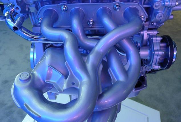
It's so cool that that's a mass-produced part. And DI gives you the capability to pass emissions with it on a high volume application, by using very late spark and injection timing on a cold start.
It's so cool that that's a mass-produced part. And DI gives you the capability to pass emissions with it on a high volume application, by using very late spark and injection timing on a cold start.
My point was that since primaries that long are workable in an emissions application, then a V8 with two setups like that with crossover pipes for 180 degree collectors should be workable.
Inboard exhaust is a much more convenient way of packaging 180 degree collectors for turbo use, and results in less wasted/leaked heat in the engine bay, but it intentionally foregoes the potential benefits of long primaries.
Which is "better"? Depends on the requirements and the system trades... but mostly the space available for the finished product.
It's only a matter of time before each cylinder has to have its own tiny catalyst 3" off the cylinder head anyway.
Thread Starter
Teching In
Joined: May 2013
Posts: 41
Likes: 0
what sort of balance between volume and velocity in an oem application is usually better? eg: would it be better to use the shear amount of exhaust being pushed through the system or would it be better to have a smaller volume of gas that moves faster through the system to spool the turbo?
or is this like cylinder heads: move the highest volume of gas at the highest velocity you can?
or is this like cylinder heads: move the highest volume of gas at the highest velocity you can?
Thread Starter
Teching In
Joined: May 2013
Posts: 41
Likes: 0
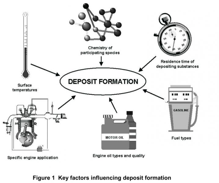
So there are a couple more topics I'd like to cover that also apply to direct injected engines in general. The first is the deposits issue, especially on the back of the intake valves and on the injector. Siemens published a very thorough study of the causes of the issue back in the early days of mass production DI engines.
Siemens GDI Valve Deposit Study
There are a lot of factors that play into the tendency towards valve deposits:
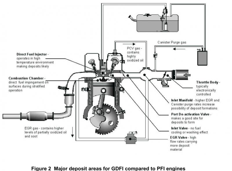
and it's not just intake valves that are prone, although intake valves and injectors seem to have the most trouble on current engine designs:
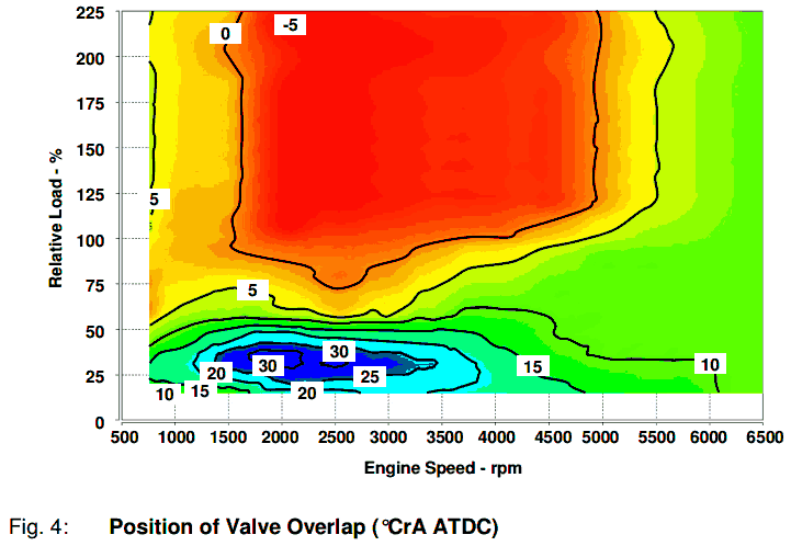
If you follow trends in engine design though, you'll see that valve timing strategies and crankcase ventilation systems have evolved to counteract this tendency towards deposits. On the Ford Ecoboost 2.0 engine for example, during cruising the valve overlap only occurs after TDC intake. This means the piston is traveling downwards when the intake valve opens, so hot and dirty exhaust gases won't be spit back out onto the intake valve.
In other valve timing strategies for overhead cam engines, the intake valve opens early, while the piston is traveling up (at the very end of the exhaust stroke), and hot exhaust gases can flow onto the intake valve due to overlap. This could be disadvantageous for limiting valve deposits.
Ford DI deposits valve timing countermeasure + I4 oil separator design
Here's a diagram of Audi's oil separator system for the current direct injected supercharged V6. This engine succeeded the generation of Audi engines that were notorious for valve deposit issues.

Audi new V6 and V8 oil separator designs
Siemens GDI Valve Deposit Study
There are a lot of factors that play into the tendency towards valve deposits:
and it's not just intake valves that are prone, although intake valves and injectors seem to have the most trouble on current engine designs:
If you follow trends in engine design though, you'll see that valve timing strategies and crankcase ventilation systems have evolved to counteract this tendency towards deposits. On the Ford Ecoboost 2.0 engine for example, during cruising the valve overlap only occurs after TDC intake. This means the piston is traveling downwards when the intake valve opens, so hot and dirty exhaust gases won't be spit back out onto the intake valve.
In other valve timing strategies for overhead cam engines, the intake valve opens early, while the piston is traveling up (at the very end of the exhaust stroke), and hot exhaust gases can flow onto the intake valve due to overlap. This could be disadvantageous for limiting valve deposits.
Ford DI deposits valve timing countermeasure + I4 oil separator design
Here's a diagram of Audi's oil separator system for the current direct injected supercharged V6. This engine succeeded the generation of Audi engines that were notorious for valve deposit issues.
Audi new V6 and V8 oil separator designs


