Cam overlap... Help me understand
 01-31-2007, 09:59 AM
#21
TECH Senior Member
iTrader: (23)
Join Date: Aug 2005
Location: Watertown, NY
Posts: 8,797
Likes: 0
Received 0 Likes
on
0 Posts
Originally Posted by great421
Really?
The ratio of the rocker arm can actually cause the valve to open sooner (with respect to the cam lobe)? Hmmm.... think about that one again.
I will agree that different rocker arms with different ratios would allow a valve to open more (or less) at a given point on the cam lobe, but given a zero clearance (i.e. - "lash") Hyd cam, the 0.050 inch lift is mearured on the cam, not at the valve, and therefore the rocker arm doesn't even play into the equation."
Now if you change rockers to higher ratios you have then brought on .006 earlier in the cams rotation and will hit .006 lift on the closing side later too, which will drop DCR.
All valve closing and opening points in relation to piston position will change with different rocker ratios.
Last edited by brad8266; 01-31-2007 at 10:05 AM.

 01-31-2007, 10:44 AM
#23
Originally Posted by brad8266
All valve closing and opening points in relation to piston position will change with different rocker ratios.
Really?
I submit to you that the the ratio of the rocker arm impacts the amount of valve lift; 150%, 165%, 170%, etc... but not when the valve actually starts to move.
Zero (i.e. - No lift) x 1.5 or 1.65 or 1.8 or (insert your favorite ratio here) always equals zero.
Any lift (i.e. - where the cam lobe begins to move off the cam circle) is, by definition, the beginning of when the valve moves, and the rocker arm ratio will indeed impact the order or magnitude of the movement of the valve, and the rate of acceleration of that valve (somewhat like the length of a connecting rod will impact the rate of acceleration of the piston; longer = faster in the middle), but NOT when the valve starts or ends, because these "hard points" (beginning and ending) are totally dependant on the actual physical dimensions of the cam lobe.
Again, just to be clear (or maybe to dig myself into a deep, dark hole where the laws of physics don't exist!); while I agree that valve opening amounts (magnitude) are 100% dependant on rocker arm ratios, valve "events" are not. If your above quoted statement were true, then we could change these camshaft hard points thru rocker arm swaps not with camshaft offset keys.
MIKE
01-31-2007, 02:52 PM
#24
6600 rpm clutch dump of death Administrator

Great 421 a cam is physically ground to certain specs. We all agree on that. You can't change the LSA for instance, as that is physically ground into the cam itself.
Where you are in error, and grossly in error is in your claim that lift is measured at the lobe. That is completely and categorically incorrect. Lets look at this
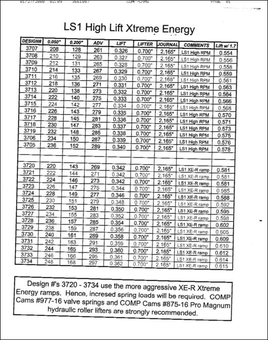
If you'll look a the lobes listed (which many folks should be familiar with) you will see tha the lift with 1.7 is listed. You will also see the lobe lift listed in a separate column.
The .006 .050, .200 are all derived in this case using a 1.7 ratio. Change that to say 1.85 and it chages with the valve opening as I stated. I agree with you that at 0 lift the base of the cam has no changed, but that is not where we measure gross duration, its measured at the valve at .006. But, because of mfg. vbariance, and because lift below .050 is pretty useless these days folks look more at the .050 and the .200 numbers.
I'll give you a simple example if you take most LSx stock cams and switch from a 1.7 toa 1.85 ration you pick up 2 degrees in duration (on the average) at .050 duration because the measured point is different.
Where you are in error, and grossly in error is in your claim that lift is measured at the lobe. That is completely and categorically incorrect. Lets look at this
If you'll look a the lobes listed (which many folks should be familiar with) you will see tha the lift with 1.7 is listed. You will also see the lobe lift listed in a separate column.
The .006 .050, .200 are all derived in this case using a 1.7 ratio. Change that to say 1.85 and it chages with the valve opening as I stated. I agree with you that at 0 lift the base of the cam has no changed, but that is not where we measure gross duration, its measured at the valve at .006. But, because of mfg. vbariance, and because lift below .050 is pretty useless these days folks look more at the .050 and the .200 numbers.
I'll give you a simple example if you take most LSx stock cams and switch from a 1.7 toa 1.85 ration you pick up 2 degrees in duration (on the average) at .050 duration because the measured point is different.
01-31-2007, 03:59 PM
#25
Launching!
iTrader: (2)
Join Date: Dec 2006
Location: Goose Creek, SC
Posts: 285
Likes: 0
Received 0 Likes
on
0 Posts
I have been reading the software manual today for Comp Cams DynoSim Advanced software. When I got to the part about cam specs. In the part about what exactly seat to seat duration is...it essentially stated that the .006 lift point is the point in the camshafts rotation that .006" of lift is measured at the lifter.
So based on that, one would presume it would be same that the .050" lift point is also measured at the lifter. So technically, the duration per a set lift point actually doesn't change. You just see higher lifts at the valves earlier with higher ratio rockers.
Hammer
So based on that, one would presume it would be same that the .050" lift point is also measured at the lifter. So technically, the duration per a set lift point actually doesn't change. You just see higher lifts at the valves earlier with higher ratio rockers.
Hammer
01-31-2007, 04:10 PM
#26
TECH Senior Member
iTrader: (23)
Join Date: Aug 2005
Location: Watertown, NY
Posts: 8,797
Likes: 0
Received 0 Likes
on
0 Posts
Originally Posted by great421
So, the beginning / opening and ending / closing points of a valve is dependant on the rocker arm ratio and not the lobe of the cam.
Really?
I submit to you that the the ratio of the rocker arm impacts the amount of valve lift; 150%, 165%, 170%, etc... but not when the valve actually starts to move.
Zero (i.e. - No lift) x 1.5 or 1.65 or 1.8 or (insert your favorite ratio here) always equals zero.
Any lift (i.e. - where the cam lobe begins to move off the cam circle) is, by definition, the beginning of when the valve moves, and the rocker arm ratio will indeed impact the order or magnitude of the movement of the valve, and the rate of acceleration of that valve (somewhat like the length of a connecting rod will impact the rate of acceleration of the piston; longer = faster in the middle), but NOT when the valve starts or ends, because these "hard points" (beginning and ending) are totally dependant on the actual physical dimensions of the cam lobe.
Again, just to be clear (or maybe to dig myself into a deep, dark hole where the laws of physics don't exist!); while I agree that valve opening amounts (magnitude) are 100% dependant on rocker arm ratios, valve "events" are not. If your above quoted statement were true, then we could change these camshaft hard points thru rocker arm swaps not with camshaft offset keys.
MIKE
01-31-2007, 06:39 PM
#27
TECH Resident
Join Date: Oct 2005
Posts: 787
Likes: 0
Received 0 Likes
on
0 Posts
J-Rod, the catalog page you shared references tappet lift. All of the lift points stated are measured at the lobe and do not factor rocker ratio. The lift with the stock rocker is listed for convenience.
Everybody should get on the same page and agree here. Cam companies list their specs in catalogs based on the standard @ .050" tappet lift, or .200"...whatever. When degreeing a cam we are not able to change the intake centerline with rocker ratio.
Brad is stating correctly that the point the lifter comes off the basecircle of the cam is fixed by the lobe. The rate of lift is affected by the rocker and its geometry. While you will certainly effect lift at the valve and the point it comes off its seat .050" I don't know that .050" is a meaningful spec there. There certainly isn't any flow action in the correct direction. The duration number is just a basis for comparison. Personally I think much of this is splitting hairs. Does anyone think changing overlap 4 degrees is going to make a meaningful difference overall?
While I understand Brad's logic with the hyd vs. solid comparison I don't necessarily agree with it. The plunger is going to compress at valve opening, if it didn't you wouldn't be able to preload hydraulic lifters. I think the plunger displacement more or less equalizes the action of the hyd/mech valve events with maybe the solid having an edge.
Last edited by andereck; 01-31-2007 at 06:49 PM.
01-31-2007, 06:48 PM
#28
TECH Senior Member
iTrader: (23)
Join Date: Aug 2005
Location: Watertown, NY
Posts: 8,797
Likes: 0
Received 0 Likes
on
0 Posts
Originally Posted by andereck
J-Rod, the catalog page you shared references tappet lift. All of the lift points stated are measured at the lobe and do not factor rocker ratio. The lift with the stock rocker is listed for convenience.
Everybody should get on the same page and agree here. Cam companies list their specs in catalogs based on the standard @ .050" tappet lift, or .200"...whatever. When degreeing a cam we are not able to change the intake centerline with rocker ratio.
Brad is stating correctly that the point the lifter comes off the basecircle of the cam is fixed by the lobe. The rate of lift is affected by the rocker and its geometry. While you will certainly effect lift at the valve and the point it comes off its seat .050" I don't know that .050" is a meaningful spec there. There certainly isn't any flow action in the correct direction. The duration number is just a basis for comparison. Personally I think much of this is splitting hairs. Does anyone think changing overlap 4 degrees is going to make a meaningful difference overall?
While I understand Brad's logic with the hyd vs. solid comparison I don't necessarity agree with it. The plunger is going to compress at valve opening, if it didn't you wouldn't be able to preload hydraulic lifters. I think the plunger displacement more or less equalizes the action of the hyd/mech valve events with maybe the solid having an edge.
.050 is important as is .006. Dynamic compression is calculated by using .006 values.
01-31-2007, 06:49 PM
#29
TECH Resident
Join Date: Oct 2005
Posts: 787
Likes: 0
Received 0 Likes
on
0 Posts
Originally Posted by brad8266
Most cams are advertised at valve lift with stock rockers, dont believe me go to comps website and look for yourself.
01-31-2007, 06:58 PM
#32
TECH Resident
Join Date: Oct 2005
Posts: 787
Likes: 0
Received 0 Likes
on
0 Posts
Originally Posted by brad8266
.050 is important as is .006. Dynamic compression is calculated by using .006 values.
What counts is how the damn thing runs...calculations be damned sometimes.
01-31-2007, 07:20 PM
#33
TECH Senior Member
iTrader: (23)
Join Date: Aug 2005
Location: Watertown, NY
Posts: 8,797
Likes: 0
Received 0 Likes
on
0 Posts
Originally Posted by andereck
Its important as a basis of general comparison. Calculations are just that. Comparing .006"-.050"-.200" and beyond are considered important as well for comparison.
What counts is how the damn thing runs...calculations be damned sometimes.
What counts is how the damn thing runs...calculations be damned sometimes.
01-31-2007, 07:23 PM
#34
TECH Resident
Join Date: Oct 2005
Posts: 787
Likes: 0
Received 0 Likes
on
0 Posts
Originally Posted by PowerShift408
I've been reading into cam overlap some over the past few days and have a few questions. I understand that on boosted applications, overlap is bad because the pressurized intake charge is going right out your exhaust. But my question, why is this ever good? What about cam overlap is good on N/A applications?
Thanks,
Alex
Thanks,
Alex
In situations where you assume your intake pressure is higher than your exhaust pressure near TDC overlap is benificial in most cases.
In a N/A engine combination overlap attempts to take advantage of low relative pressure created by the exiting exhaust. If the intake valve is opened as the pressure in the chamber drops below that of the intake, the intake charge will be "vacuumed" into the chamber which starts its flow. Depending on certain factors, such as header and exhaust design, sealing, temperature, intake design, rpm and the azimuth of venus a measurable portion of the intake charge will be drawn out of the exhaust before the exhaust valve closes. This isn't necessarily bad. The idea is to maximize your cylinder volume at WOT with a cool, dense charge. Overlap's effects are greatly influenced by operating rpm. When the engine is operated under an intake vacuum situation the flow reverses towards the lower pressure intake and high overlap created charge dillution effectively creating EGR and making the engine act smaller.
Now in a belt driven blower situation overlap has the above effect but also can allow you to fill more volume with a denser charge as you are filling the chamber too and aren't relying on just the changing cylinder displacement and inertia for fill. The whole "blowing out your boost" thing is overplayed and dramaticized.
Turbos? I know squat about their particular requirements but its all about the pressures. From what I understand you're doing pretty well on a street turbo system to a achieve a 2:1 exhaust to intake pressure ratio so the flow would automatically be biased from exhaust to the lower pressure intake under high load operation which can't be good so it seems overlap is a critical spec there and you may not want any at all depending on the pressures from a particular turbo configuration. There's smart guys on here that can school you about their requirements. I'm just not one of them.
Hope it helps some.
::putting on flak jacket::
01-31-2007, 07:26 PM
#35
TECH Resident
Join Date: Oct 2005
Posts: 787
Likes: 0
Received 0 Likes
on
0 Posts
Originally Posted by brad8266
right but once the valve closes to .006 compression can begin. Thats why it it used in determining compression.
But yes, when hand or slow cranking I suspect compression doesn't start until .000".
I was trying to back you up??
01-31-2007, 08:08 PM
#36
Originally Posted by andereck
Sorry I'm not trying to be a post ***** and I would like to address your question if you're still watching.
In situations where you assume your intake pressure is higher than your exhaust pressure near TDC overlap is benificial in most cases.
In a N/A engine combination overlap attempts to take advantage of low relative pressure created by the exiting exhaust. If the intake valve is opened as the pressure in the chamber drops below that of the intake, the intake charge will be "vacuumed" into the chamber which starts its flow. Depending on certain factors, such as header and exhaust design, sealing, temperature, intake design, rpm and the azimuth of venus a measurable portion of the intake charge will be drawn out of the exhaust before the exhaust valve closes. This isn't necessarily bad. The idea is to maximize your cylinder volume at WOT with a cool, dense charge. Overlap's effects are greatly influenced by operating rpm. When the engine is operated under an intake vacuum situation the flow reverses towards the lower pressure intake and high overlap created charge dillution effectively creating EGR and making the engine act smaller.
Now in a belt driven blower situation overlap has the above effect but also can allow you to fill more volume with a denser charge as you are filling the chamber too and aren't relying on just the changing cylinder displacement and inertia for fill. The whole "blowing out your boost" thing is overplayed and dramaticized.
Turbos? I know squat about their particular requirements but its all about the pressures. From what I understand you're doing pretty well on a street turbo system to a achieve a 2:1 exhaust to intake pressure ratio so the flow would automatically be biased from exhaust to the lower pressure intake under high load operation which can't be good so it seems overlap is a critical spec there and you may not want any at all depending on the pressures from a particular turbo configuration. There's smart guys on here that can school you about their requirements. I'm just not one of them.
Hope it helps some.
::putting on flak jacket::
01-31-2007, 08:43 PM
#37
TECH Resident
Join Date: Oct 2005
Posts: 787
Likes: 0
Received 0 Likes
on
0 Posts
Originally Posted by PowerShift408
That's actually one of the better responses I've had. I've always heard the "blowing out boost" theory with cam overlap, but perhaps that is not the case.
Boost is both an easy yet sometimes complicated aspect of FI combination building to grasp. Boost along with IAT is a measure of charge density inside the area the boost guage is referencing. It is created by supplying more airflow to the intake than what the engine would normally inhale on its own. The amount of boost shown is affected by displacement, rpm, and intake and exhaust restrictions or the volumetric efficiency of the engine.
Traditional hotrod mods such as porting cylinder heads, free flowing exhaust, revised valve timing, intake modifications and others all try to increase the mass of the cylinder fill which I like to compare to making the engine larger. Since "boost" is affected by displacement; given the same airflow a smaller engine will generally read less bost than the larger one, breathing enhancements made will show less boost as the engine is breathing deeper and has more volume to fill. This means more air went into filling the cylinder which lowered the pressure shown on the guage. Overlap helps scavenge the clearance volume of hot exhaust gasses which are taking up fill volume.
This is why people who have installed a larger cam on a belt driven blower sometimes think they've lost boost. Yes the pressure went down in the intake where the guage is referenced, but more charge went into the cylinder where it will create power.
Now it is entirely possible and somewhat necessary to lose some of this charge out the exhaust but the effect of this diminishes with increasing rpm as there is less and less time for flow to start and short circuit across the chamber.
You can simulate this with certain higher end engine simulation programs to prove the concept to yourself. Engine Analyzer Pro is one of them that will calculate short circuit % and also give you residual exhaust percentage. Power will increase when you are able to reduce the residual % and more effectively fill the cylinder/chamber.
01-31-2007, 08:50 PM
#38
TECH Senior Member
iTrader: (23)
Join Date: Aug 2005
Location: Watertown, NY
Posts: 8,797
Likes: 0
Received 0 Likes
on
0 Posts
I agree with you 100% on the blown motor thing. I have been trying to get people to listen to that for a while. Everyone just thinnks that high overlap cams are bad for blowers because of boost bleed off. What they fail to think of is that it isnt boost that matters, its airflow. The more restriction in the engine, the more boost that will be read in the manifold. But manifold pressure means nothing, its all about cylinder pressure, thats what gives you the power.
You can take a blower with a 3" pulley and a stock cam and it will read more manifold boost but have lower airflow and make less power than a larger cam with more overlap that will flow more air, but make less manifold pressure.
People are just too caught up in boost numbers like boost is what determines power. Although when using a blower you dont need much cam to get moving, all you gotta do is swap the pulley to bump up.
02-01-2007, 12:15 AM
#39
TECH Resident

Join Date: Dec 2004
Location: K-W, Ontario
Posts: 845
Likes: 0
Received 0 Likes
on
0 Posts

Cool discussion going on. I'd like to touch on a few more points as well:
Hydraulic and Solid lifters react very differently under spring load and RPM.
I don't think relating the two are a good thing, especially when talking terms
of pre-load and lash.
A hyd. lifter is very sloppy and can change valve duration at any given RPM,
at any given time. This action is more apparent as pre-load increases.
Those of you that have tested different pre-load settings understand that
limited seat travel makes for good RPM power and improved idle, throttle
response, etc.
The points made about using lash as clearances as opposed to valve action
is also well put. Getting the valve timing 'bang on' with the proper lobe and
as little lash/pre-load as possible is IMO the best bet.
Setting initial solid lash is tricky until the engine is warmed up. If even one
valve is hanging open 0.001" too much, it can really screw the manifold pressure.
If you have ever used a vacuum gauge while setting a solid valve train, you
can see the needle bounce wildly if an intake valve is slightly open.
That brings on the next point about compression before 0.000" lift. As RPM
and VE increase, the amount of charge that tries to escape as the valve
approaches IVC creates a higher impedence to flow and raises the pressure in the
cylinder.
Having said that, I never bought the story about valve lifts under 0.050" not
being useful. I'd hate to see anyone throw that first and last 0.050" of lift away,
or not consider it.
The overlap period is an important event in the cycle and there isn't much lift
occuring at this point.
Most of the time when I'm thinking about cams, I think in terms of advertised
duration for that reason.
4 degrees would make a difference for sure. How much is tough to quantify.
I would guess you could shift TQ and HP peaks by around 100-200 RPM.
Mind you, every motor is going to react in a different manner, but in general
I can see that extra overlap making more mid to high RPM power if the engine
is setup for it.
Hydraulic and Solid lifters react very differently under spring load and RPM.
I don't think relating the two are a good thing, especially when talking terms
of pre-load and lash.
A hyd. lifter is very sloppy and can change valve duration at any given RPM,
at any given time. This action is more apparent as pre-load increases.
Those of you that have tested different pre-load settings understand that
limited seat travel makes for good RPM power and improved idle, throttle
response, etc.
The points made about using lash as clearances as opposed to valve action
is also well put. Getting the valve timing 'bang on' with the proper lobe and
as little lash/pre-load as possible is IMO the best bet.
Setting initial solid lash is tricky until the engine is warmed up. If even one
valve is hanging open 0.001" too much, it can really screw the manifold pressure.
If you have ever used a vacuum gauge while setting a solid valve train, you
can see the needle bounce wildly if an intake valve is slightly open.
That brings on the next point about compression before 0.000" lift. As RPM
and VE increase, the amount of charge that tries to escape as the valve
approaches IVC creates a higher impedence to flow and raises the pressure in the
cylinder.
Having said that, I never bought the story about valve lifts under 0.050" not
being useful. I'd hate to see anyone throw that first and last 0.050" of lift away,
or not consider it.
The overlap period is an important event in the cycle and there isn't much lift
occuring at this point.
Most of the time when I'm thinking about cams, I think in terms of advertised
duration for that reason.
Does anyone think changing overlap 4 degrees is going to make a meaningful difference overall?
I would guess you could shift TQ and HP peaks by around 100-200 RPM.
Mind you, every motor is going to react in a different manner, but in general
I can see that extra overlap making more mid to high RPM power if the engine
is setup for it.
Last edited by Adrenaline_Z; 02-01-2007 at 12:29 AM.
02-01-2007, 01:00 AM
#40
I've heard this before, and I still stand by it. Boost is not the measure of air moving, but a measure of the resistance to air moving. What really matters is the CFM that is moving.
For instance, when I had my SRT-4, it boosted 14 psi. When I put on a freer flowing intake and a better flowing intercooler, I got less boost. However, I was making more power because more air was getting into the motor because there was less resistance in the intake tract.
I guess the same principle applies here.