When you click on links to various merchants on this site and make a purchase, this can result in this site earning a commission. Affiliate programs and affiliations include, but are not limited to, the eBay Partner Network.
I have a thread going in the LT1 section but think I'll get more answers here. A few weeks ago I picked up a 94 Z28 that has a Pilot wheel installed, the horn is not hooked up and I'm trying to get it to work along with getting rid of the ABS light (Still a street car).
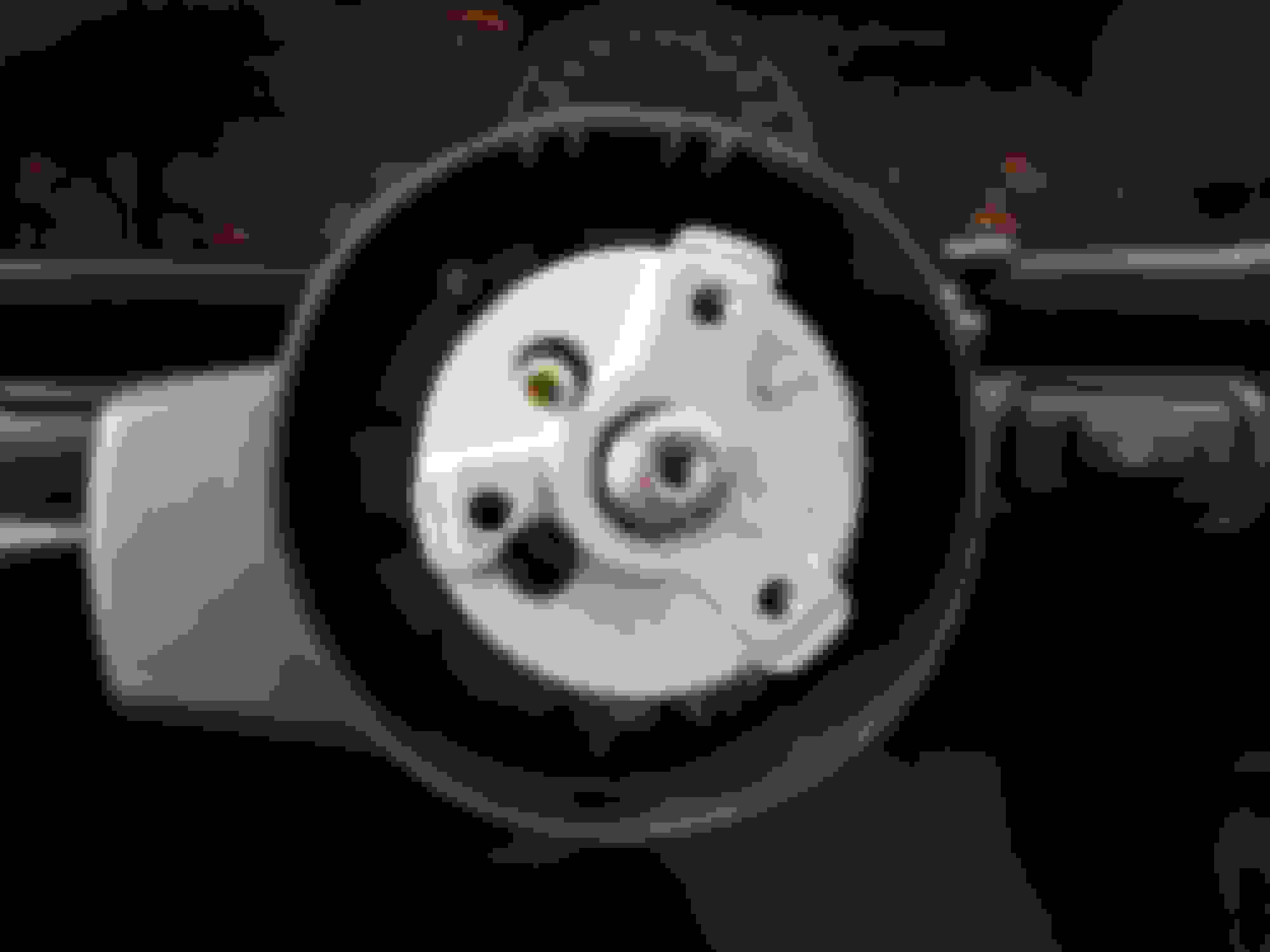
Here is where I'm at.. Its missing the steering wheel horn button contact but I'm not exactly sure thats all I'll need to get this working. This wheel has this Grant adapter and as you can see in the pictures, all I have is the hub. I don't have that plate with what looks like a wire for the horn, do I need this to get my horn hooked up or can I use a stock steering wheel contact button for mine that rides on the clock spring? Also, any tips on getting that hub off? The autozone pullers are 2 post and wont work.
You need a special puller for the grant adapter. I think it's 5891 or you can make your own if you have the tools.
To get the horn working you need the horn wire along with the spring and the plastic sleeve with both of the side tabs intact. You also need the cancel cam to have intact slots on each side. You can cut new slots with a small file if you need since the slots tend to break out.
The horn has nothing to do with the clockspring so at least you have that going for you lol
For alignment you have to get the wheels dead straight to start. Then bolt the wheel to the adapter and line up the steering wheel so it's straight and slide it onto the shaft (it doesn't have to be fully seated, you just need to get the teeth to engage). Then unbolt the wheel from the adapter and mark the adapter and the end of the shaft with a paint pen or a scribe (I use the edge of a flathead screwdriver). After that you'll have your alignment marks so you can take it apart and put it together in any position without worry. If you find the wheel is a hair off when driving straight either pull the adapter and move it a tooth over or adjust the alignment if you think it's due.
For alignment you have to get the wheels dead straight to start. Then bolt the wheel to the adapter and line up the steering wheel so it's straight and slide it onto the shaft (it doesn't have to be fully seated, you just need to get the teeth to engage). Then unbolt the wheel from the adapter and mark the adapter and the end of the shaft with a paint pen or a scribe (I use the edge of a flathead screwdriver). After that you'll have your alignment marks so you can take it apart and put it together in any position without worry. If you find the wheel is a hair off when driving straight either pull the adapter and move it a tooth over or adjust the alignment if you think it's due.
I tried that and the splines seem to be keyed for one position only unless I was missing something while I had it all apart. I was in a rush putting it back together since I needed the car but will recheck. I'm going to be swapping in an LS1 steering shaft in the coming days so after I re-index it with the wheels off the ground I can figure out what the alignment issue is. The stock rag joint has a ton of slop in it so that needs to be done before aligning the steering regardless.
The standard grant adapter doesn't exactly fit the LS shaft. The LS shaft has splines spaced slightly different from the adapter. Basically you get 1 shot at it and if you ever want to pull the adapter off it's not fun. I consider mine an interference fit lol
The standard grant adapter doesn't exactly fit the LS shaft. The LS shaft has splines spaced slightly different from the adapter. Basically you get 1 shot at it and if you ever want to pull the adapter off it's not fun. I consider mine an interference fit lol
Good to know. I was planning on getting:GRT-761, GRT-3196, GRT-5649
The standard grant adapter doesn't exactly fit the LS shaft. The LS shaft has splines spaced slightly different from the adapter. Basically you get 1 shot at it and if you ever want to pull the adapter off it's not fun. I consider mine an interference fit lol
I'm only changing the steering shaft section from the firewall to the rack, doesn't have anything to do with the adapter.
I have to pull everything apart again because my right turn signal stopped cancelling, possible that the new spring wasn't seated properly and fell out . Good thing it only takes 15 minutes to do with this wheel lol
*Edit: What I meant about it being keyed differently actually had nothing to do with the adapter now that I remembered. It appears that in order to change the alignment of the wheel you need to re-orient the lock plate/ or whatever is under the lockplate so the turn signal cam can line up with the hole. The issue is that they lock plate is keyed to go on one way only, so I'm assuming the wheel is seated correctly onto the column shaft and its a suspension alignment issue. (The car tracks perfectly straight though and has a bunch of suspension work done to it).
So the wheel, adapter, horn, and LS1 steering shaft have all been taken care of and work perfectly. It turned out the actual wheel alignment is off on the car despite it tracking straight.
Anyways the last thing I want to take care of in relation to steering is the airbag light. After doing some digging I understand that I need to install a resistor(s) but haven't come up with the exact value I need. It seems to be 2.2ohms at 1/2 watt
The other question I have is it seems that every thread I've seen mentions you need to splice in the resistor at the airbag end of the connector coming out of the steering column. My problem is whoever initially did this install cut the yellow wire down very short and I have no access to it short of taking the column apart more. Can I splice it in under the column on the dash side? Also I'm pretty weak with electrical work, I'm basically splicing in both ends of the resistor with the power wire right? Thank you
PS, this has probably been the best info I've found. Can anyone confirm?
Originally Posted by white01ss
Bringing this back from the dead...
From the air bag pdf I got this from it:
DTC B0016: PASSENGER DEPLOYMENT LOOP RESISTANCE LOW
Sets with < 1.3 ohms, Clears with > 1.3 ohms
DTC B0017: PASSENGER DEPLOYMENT LOOP OPEN
Sets with > 3.7 ohms, Clears with < 3.7 ohms
DTC B0022: DRIVER DEPLOYMENT LOOP RESISTANCE LOW
Sets with < 1.3 ohms, Clears with > 1.3 ohms
DTC B0026: DRIVER DEPLOYMENT LOOP OPEN
Sets with > 4.8 ohms, Clears with < 4.8 ohms
PASSENGER's side needs to be 1.3 - 3.7 ohms
DRIVER's side needs to be 1.3 - 4.8 ohms
So 2.5 ohm is a nice middle ground for both air bags. (2) 5 ohms or (4) 10 ohms in parallel (as mentioned before) would do the trick.
Once this is all figured out, it would be good to post a picture of exactly what plug/wires the resistor is being used on. Show the wire colors. A picture is worth a 1000 words.
6 Common C5 Corvette Failures and What's Involved In Repairing Them
Slideshow: From wobbling harmonic balancers to failed EBCMs, these are the issues that define long-term C5 ownership and what repairs typically involve.
Retro Modern Bandit Pontiac Trans AM Comes With Burt Reynolds' Autograph
Slideshow: A modern Camaro transformed into a retro icon, this limited-run "Bandit" build blends nostalgia with brute force in a way few revivals manage.
Top 10 Greatest Cadillac V Series Performance Models Ever, Ranked
Slideshow: Cadillac didn't just crash the high-performance luxury vehicle party, it showed up loud, supercharged, and occasionally a little unhinged...
Coachbuilt N2A Anteros Is an LS2-Powered C6 Corvette In Italian Clothes
Slideshow: A one-off sports car that looks like a vintage Italian exotic-but hides a C6 Corvette underneath-just sold for the price of a new mid-engine Corvette.


 . Good thing it only takes 15 minutes to do with this wheel lol


