When you click on links to various merchants on this site and make a purchase, this can result in this site earning a commission. Affiliate programs and affiliations include, but are not limited to, the eBay Partner Network.
Can anyone shed a little more light on how to measure the servo pin length for the rear band? I've seen a couple threads and a YouTube video but I'm uncertain if the band is supposed to be applying ANY tension with the piston "home" at the top of its bore. If zero tension is desired then my pin is way, way too long!
Really could use those special tools right now (j121370 and j38737)!
Edit: This is on a 2003 4L80E.
S.F.
Last edited by StolenFox; Sep 10, 2016 at 02:30 PM.
The Pin will exert pressure on the Band, But NOT apply the band with the Servo Cover bolted down.
There is a Chamfer that is machined at a angle in the Servo Bore, The Apply Servo Seal sits right below the chamfer when the Servo Cover is bolted down.
I want you to leave off the 2 Spings, And temporarily assemble the Servo Pin, Spacer, & E-Clip on the Servo Piston, Insert the Servo in the Bore too where the Sealing Ring Groove is just below the Chamfer.
The distance from this point to where you can no longer push the Servo in any further Is Your Band Clearance......I like .060-.080". After clearance is verified, Reassemble with the Springs in place.....MAKE SURE the Output turns both directions!!
If you cannot get the Servo Seal Grooves down below the Chamfer, Suspect a mispositioned Rear Band (Not engaged in the 2 Anchors).
Late 4L80E's are different than Early 4L80E/TH400 as for the Servo Pin, Servo Piston, & Spacer. That is why there is a discrepancy in the pictures you were looking at.
The Pin will exert pressure on the Band, But NOT apply the band with the Servo Cover bolted down.
There is a Chamfer that is machined at a angle in the Servo Bore, The Apply Servo Seal sits right below the chamfer when the Servo Cover is bolted down.
I want you to leave off the 2 Spings, And temporarily assemble the Servo Pin, Spacer, & E-Clip on the Servo Piston, Insert the Servo in the Bore too where the Sealing Ring Groove is just below the Chamfer.
The distance from this point to where you can no longer push the Servo in any further Is Your Band Clearance......I like .060-.080". After clearance is verified, Reassemble with the Springs in place.....MAKE SURE the Output turns both directions!!
If you cannot get the Servo Seal Grooves down below the Chamfer, Suspect a mispositioned Rear Band (Not engaged in the 2 Anchors).
Late 4L80E's are different than Early 4L80E/TH400 as for the Servo Pin, Servo Piston, & Spacer. That is why there is a discrepancy in the pictures you were looking at.
Ok, the photo taken of the piston sitting above the case is with the pin temporarily assembled like you instruct. I will attempt to measure clearance today with a dial indicator and report back. If I did somehow screwup and have to pull the internals, ill need to get new bolts for the fourth clutch housing and for the center support as they are single use correct?
Testing method is as follows: The piston was set in the bore where it was just below the sealing surface. Basically the piston chamfer and the bore chamfer were at the same elevation. At this point everything rotates as normal. If I preload the piston any further, you can begin to feel a slight drag as the band starts to drag on the drum.
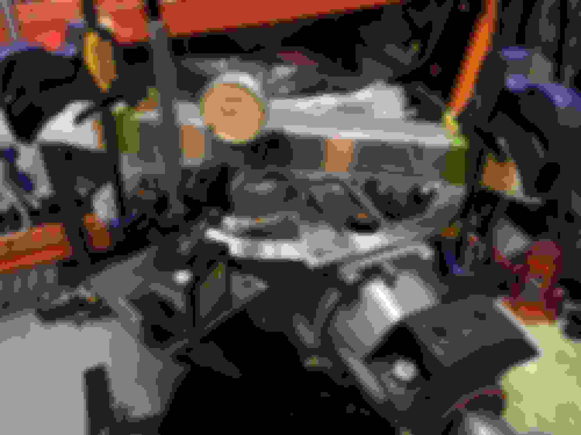
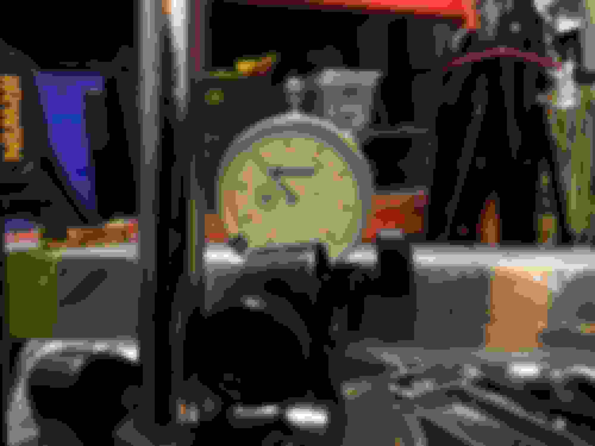
Rudimentary test rig:
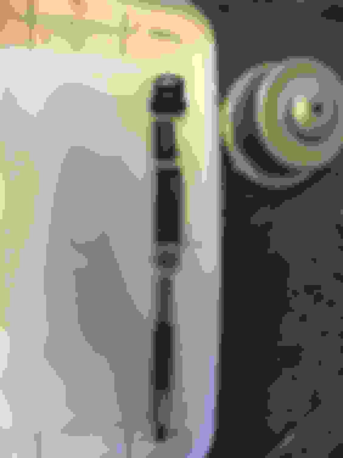
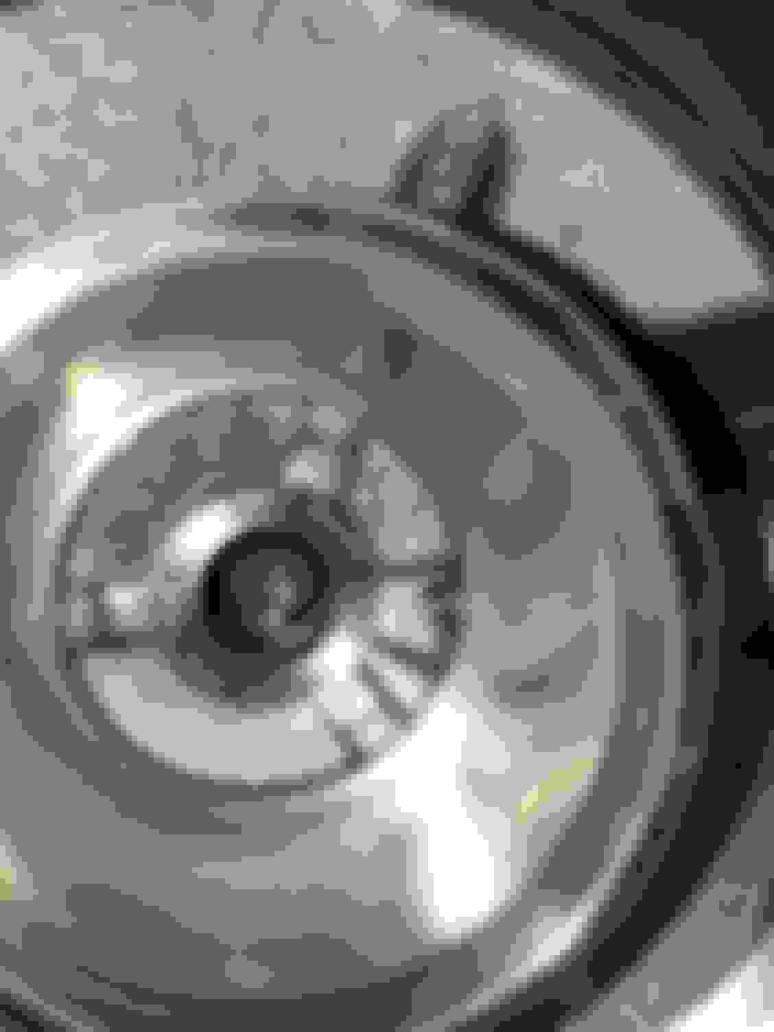
The above pics are various angle shots of the piston at "home" in the bore just below the chamfer.
Then, because the indicator measure and upward motion, I preloaded it (with the piston home) to measure .200 so when the piston is compressed the dial measurement will decrease and then I can just subtract to get the preload number.
I repeated the test twice and came up with a clearance of .125 which would then suggest that the pin is approx .052 short. Does that make sense given the band is new and the drum it rides on was used but with no grooving in it? I am concerned that if I add length to the pin that the band will drag and burn up. It's hard to discern whether the drag a human hand feels while trying to rotate would actually matter during operation. As the piston move down in the bore from the home position the drag gets progressively greater but even bottomed out in the bore it never gets to the point where I can't turn the yoke (albeit with much effort required). Perhaps I can still turn it because of the extra leverage afforded by the driveshaft yoke? It would be significantly harder I'm sure if I was just trying to turn the output shaft itself.
S.F.
Last edited by StolenFox; Sep 11, 2016 at 08:59 AM.
With the indicator on the edge on the piston like that.....You may get a false reading.
When I do this particular way.....I go by feel....Because I use my hand to push the Piston down.
Now....Clamping the Band all the way down by FORCE......125" is not bad at all & still gives quite a bit of room for wear in service.
There is more than one way too skin this Cat!!!!!! And all these specifications can cloud our judgment
There are only TWO things that really matter here...........
1. The Band is able to grip the Reaction Carrier without the "Ends" of the Band hitting each other.
2. The Servo is able to fully Clamp the Band down without bottoming out in the Bore.
**Take future wear in to account**
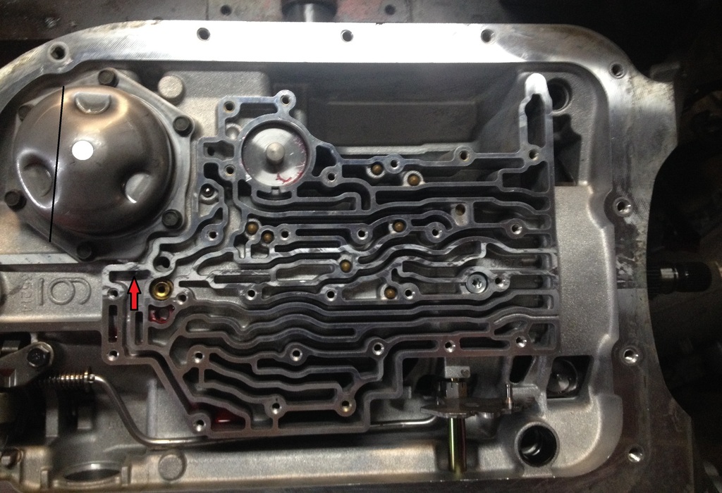
If you have a extra Servo Cover.......Cut off the section shown (Black Line), Drill a hole in the Cover (White Circle), Weld a nut over the hole (3/8-16 works well), Now you can bolt the "Test Cover" over the Servo.
Run a 3/8-16 bolt down to where it touches the Servo pin, Set up you dial indicator to zero at the top of the bolt, Crank the bolt down with a open end wrench 'til snug, This reading is more absolute & .125"-.165" is acceptable.
With the indicator on the edge on the piston like that.....You may get a false reading.
When I do this particular way.....I go by feel....Because I use my hand to push the Piston down.
Now....Clamping the Band all the way down by FORCE......125" is not bad at all & still gives quite a bit of room for wear in service.
There is more than one way too skin this Cat!!!!!! And all these specifications can cloud our judgment
There are only TWO things that really matter here...........
1. The Band is able to grip the Reaction Carrier without the "Ends" of the Band hitting each other.
2. The Servo is able to fully Clamp the Band down without bottoming out in the Bore.
**Take future wear in to account**
If you have a extra Servo Cover.......Cut off the section shown (Black Line), Drill a hole in the Cover (White Circle), Weld a nut over the hole (3/8-16 works well), Now you can bolt the "Test Cover" over the Servo.
Run a 3/8-16 bolt down to where it touches the Servo pin, Set up you dial indicator to zero at the top of the bolt, Crank the bolt down with a open end wrench 'til snug, This reading is more absolute & .125"-.165" is acceptable.
Awesome, thank you for that explanation! Sounds like I should be good but I see where the piston could rock in the bore and give me false readings. Looks like I need to find another servo cover to build the test rig.
Gas Monkey Built a 6-Wheel Ferrari Testarossa With a Corvette LT4 Engine
Slideshow: The controversial Ferrari F6 swaps its original flat-12 for a Corvette Z06-derived LT4 V8 and sends power to four rear wheels through a custom-built drivetrain.
7 Most Reliable High-Performance Engines GM Has Ever Built
Slideshow:These GM engines didn't just make huge power, they survived abuse, boost, track days, and six-digit mileage with a reputation for refusing to quit.
6 Common C5 Corvette Failures and What's Involved In Repairing Them
Slideshow: From wobbling harmonic balancers to failed EBCMs, these are the issues that define long-term C5 ownership and what repairs typically involve.
Retro Modern Bandit Pontiac Trans AM Comes With Burt Reynolds' Autograph
Slideshow: A modern Camaro transformed into a retro icon, this limited-run "Bandit" build blends nostalgia with brute force in a way few revivals manage.
Top 10 Greatest Cadillac V Series Performance Models Ever, Ranked
Slideshow: Cadillac didn't just crash the high-performance luxury vehicle party, it showed up loud, supercharged, and occasionally a little unhinged...
Coachbuilt N2A Anteros Is an LS2-Powered C6 Corvette In Italian Clothes
Slideshow: A one-off sports car that looks like a vintage Italian exotic-but hides a C6 Corvette underneath-just sold for the price of a new mid-engine Corvette.







 Rear band pin length?