Twin intank walbro install pics
 02-04-2013, 01:25 AM
#1
On The Tree
Thread Starter
iTrader: (14)

Join Date: Jan 2005
Location: St. Louis, MO
Posts: 151
Likes: 0
Received 0 Likes
on
0 Posts

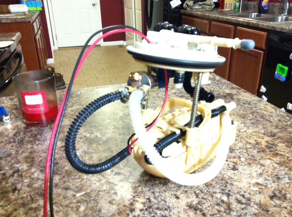
I have been working on this for a couple weeks, and finally got to a good enough point where I could post some pics. Unfortunately I will be unable to work on the car for about 4 months, so can't finish up the loose ends and test out the system. This would be very inexpensive if the stock fuel lines where used, but I decided to do -8 pushlock feed and return to ensure the fuel system would not be a limiting factor. Here are some pics.
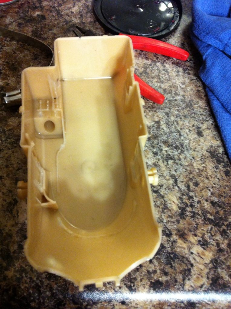
Pics of the bucket mods, pretty much gutted everything top and bottom
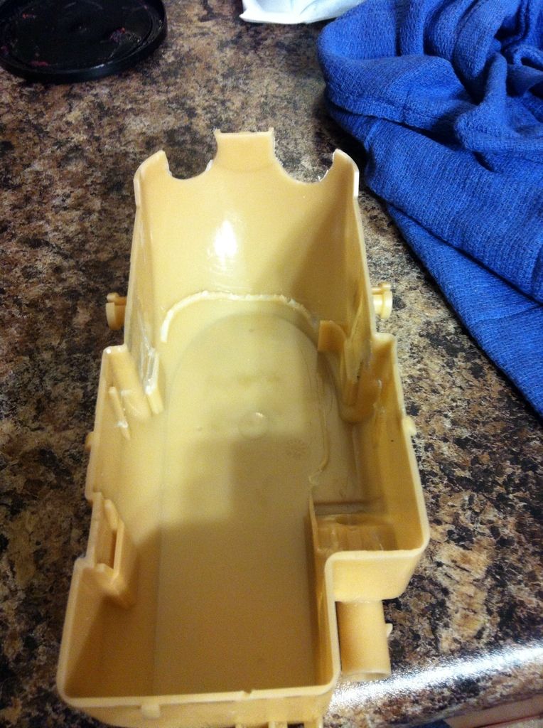
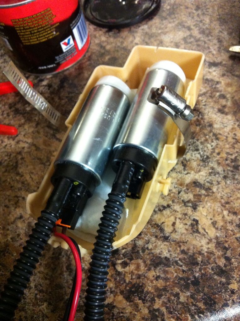
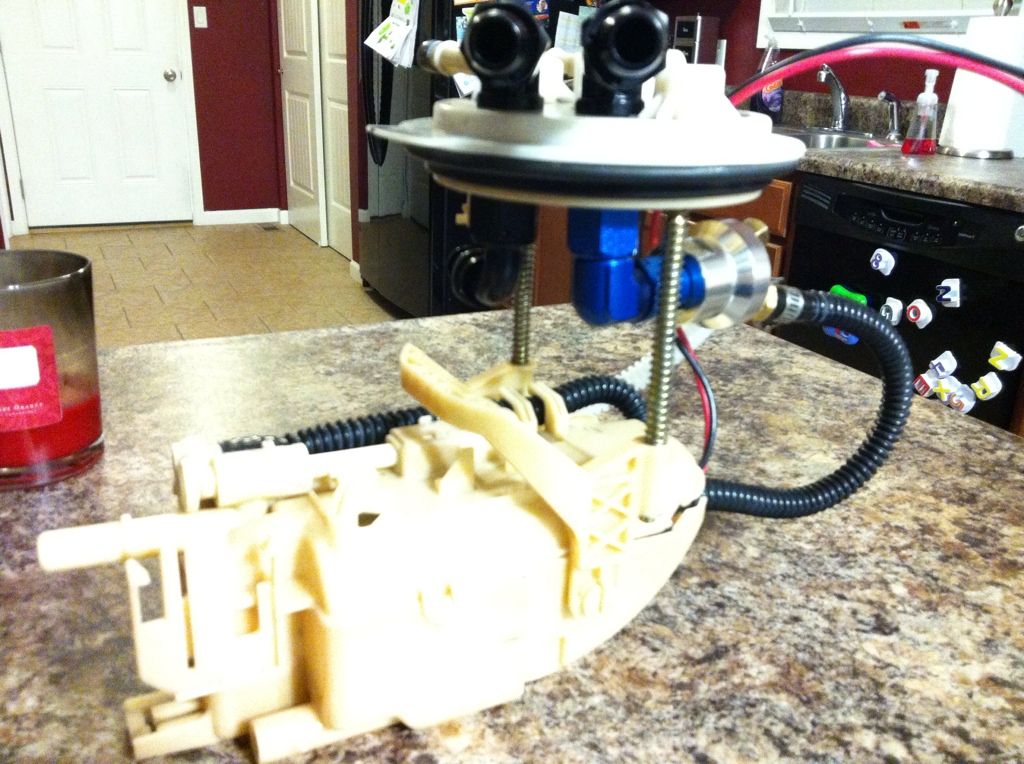
Walbro GSS340's with Airtex FS140 strainers. The worm clamp holds the pumps off the floor of the bucket, giving space under the pumps.
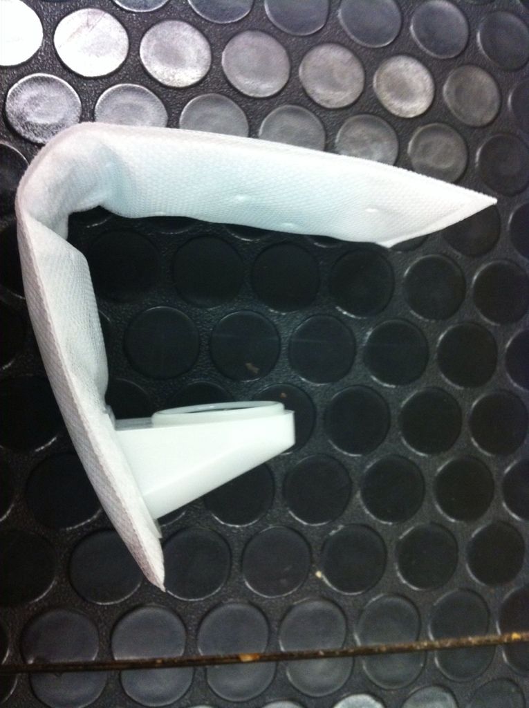
Pic of the FS140 strainers (thanks to a friend at Advanced Auto Parts who somehow found one to work with the large pump inlet)
Couple pics mostly together. Had to turn the "horseshoe" part 180 degrees to make room for the fittings, which also slides the bucket toward the rear 2", giving room for the hoses. The primary pump still runs through the jet pump like normal, and the second pump bypasses the jet pump and goes straight to the Y. Secondary pump will be activated by a Hobbs switch. The return line "not installed yet" will be routed from the bulkhead to the stock return port on the bucket with the stock regulator removed. Even though I don't plan to run the car below a quarter tank, I will still add a few small holes to the bucket to allow fuel to fill it if the fuel level drops below the top of the bucket.
Pics of the bucket mods, pretty much gutted everything top and bottom
Walbro GSS340's with Airtex FS140 strainers. The worm clamp holds the pumps off the floor of the bucket, giving space under the pumps.
Pic of the FS140 strainers (thanks to a friend at Advanced Auto Parts who somehow found one to work with the large pump inlet)
Couple pics mostly together. Had to turn the "horseshoe" part 180 degrees to make room for the fittings, which also slides the bucket toward the rear 2", giving room for the hoses. The primary pump still runs through the jet pump like normal, and the second pump bypasses the jet pump and goes straight to the Y. Secondary pump will be activated by a Hobbs switch. The return line "not installed yet" will be routed from the bulkhead to the stock return port on the bucket with the stock regulator removed. Even though I don't plan to run the car below a quarter tank, I will still add a few small holes to the bucket to allow fuel to fill it if the fuel level drops below the top of the bucket.
Last edited by Frostbite; 09-09-2013 at 03:38 PM.
 02-04-2013, 09:25 AM
#5
On The Tree
Thread Starter
iTrader: (14)
Join Date: Jan 2005
Location: St. Louis, MO
Posts: 151
Likes: 0
Received 0 Likes
on
0 Posts
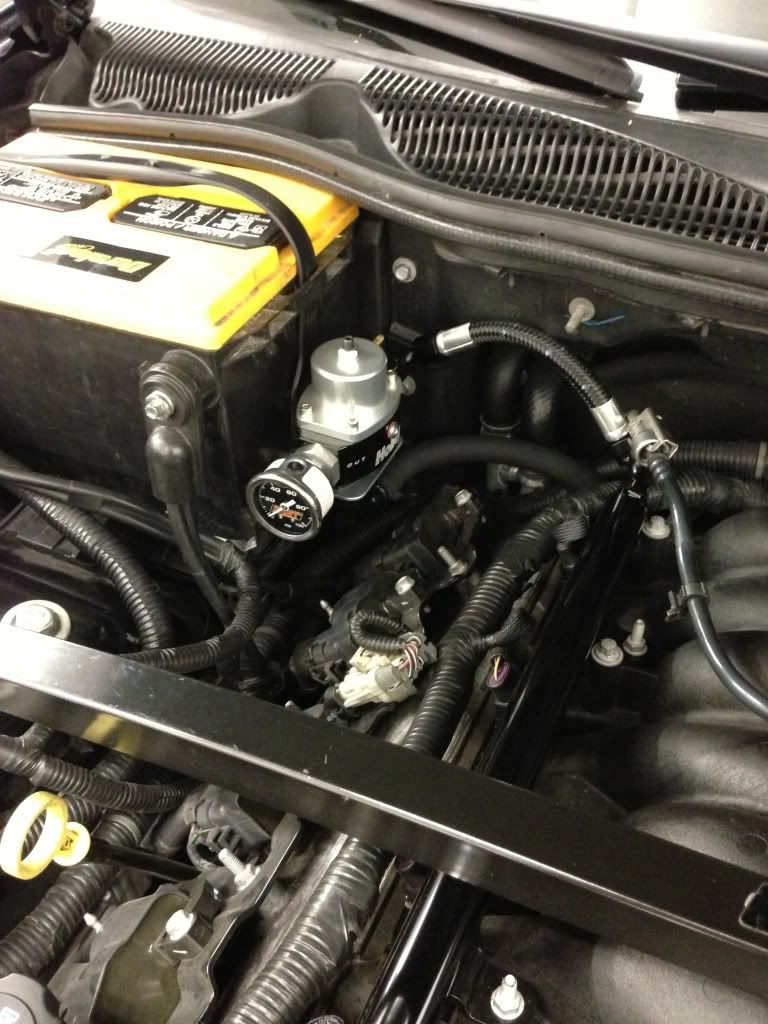
I would guess it would be good for 1000rwhp with the -8 line and maybe 800rwhp with stock lines, but only time will tell. That is a air compresser coupler bought from home depot (idea taken from Mighty Mouse's twin walbro F-body write-up in the fuel section). The other line is my return, which will be ran to the port the stock regulator was connected to. Here is a pic of the coupler, although I had to replace the straight -8 to 3/8 fitting with a 90degree one, I forgot the bucket height compacted so much.

02-04-2013, 09:31 AM
#6

Remember, pumps vary on pressure, the higher the pressure, especially the GSS34x, will drop in flow, limiting your potential hp.
Twin walbro gss34x used here @40psi @ 13.5v would support 1000hp no problem.
the same setup at 70psi, your pushing it to even get 800.
The Setup an interesting idea. though, i would have kept the rubber flap in there as that stops fuel from leaving the bucket when accelerating (and the fuel sloshes to the rear of the tank) - the idea of more holes in the side I dont like but..., I would also try to get that return back into the bucket in the top, not that side hole where the regulator streamed into... two pumps in there would scavenge that bucket dry in a hurry.
02-04-2013, 09:52 AM
#7
On The Tree
Thread Starter
iTrader: (14)
Join Date: Jan 2005
Location: St. Louis, MO
Posts: 151
Likes: 0
Received 0 Likes
on
0 Posts
I believe you need at least 50psi for the jet pump to work correctly, but deatchwerks 300's would fit also if the walbro's were not enough. I tried to keep the flapper, but it was hitting the second pump sock. I will probably add some holes to the top cover, and a very small hole on the bottom edge of the front side. I figure if the fuel level drops below the top of the bucket, I will probably be nursing it to a gas station. Lol
Trending Topics
02-04-2013, 03:06 PM
#8
TECH Regular
iTrader: (9)
Join Date: May 2009
Location: Lake Worth,TX
Posts: 498
Likes: 0
Received 0 Likes
on
0 Posts
after looking at the setup, why do you really even need the bottom of the bucket anyways??
seems like just letting the pumps be open to the gas would eliminate any starvation issue. secure the pumps to top portion of bucket.
could you just run a line and dump that return into the driver side of the tank?? keeping gas flowing and still using the jet pump.
seems like just letting the pumps be open to the gas would eliminate any starvation issue. secure the pumps to top portion of bucket.
could you just run a line and dump that return into the driver side of the tank?? keeping gas flowing and still using the jet pump.
02-04-2013, 03:18 PM
#9
Thats right, the jet pump requires a higher pressure to work correctly.
I was just giving values that at a lower pressure, more flow is capable and thus more headroom for hp.
The 300's would work.
as for pumps out in the open, the lower the fuel level in the tank, the worse this scenario comes to light.
during Acceleration the fuel will move to the back of the tank, leaving the pumps high and dry. Cavitation will happen, pressure will drop, one is probably FI to consider this route in the first place, so this would be a big problem.
Nothing more annoying than: damn, Im at 1/4 tank, I consciously cannot floor it to show this guy up beside me.
02-04-2013, 04:05 PM
#10
On The Tree
Thread Starter
iTrader: (14)
Join Date: Jan 2005
Location: St. Louis, MO
Posts: 151
Likes: 0
Received 0 Likes
on
0 Posts
I ran a similar setup in my turbo SS camaro, and it wasn't to bad keeping it above a 1/4 tank (as long as the wife doesn't drive it lol). Also, not sure how well the siphon system works, but doesn't it keep the pump side full until the secondary side is empty? Assuming that is true, then an indicated 1/4 tank would still give you a half tank on the primary tank. I don't plan on depending on that math, but it's nice to know a 1/4 tank might be more on the pumps.
 09-08-2013, 09:03 PM
#14
On The Tree
Thread Starter
iTrader: (14)
Join Date: Jan 2005
Location: St. Louis, MO
Posts: 151
Likes: 0
Received 0 Likes
on
0 Posts
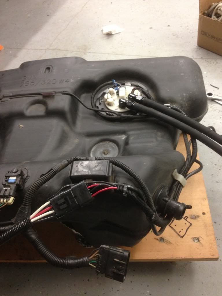
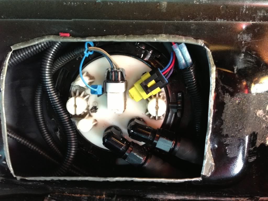
Finally got back from working in Arizona for 7 months, and finally got the setup finished and running. The jet pump is working perfectly, I ran the car down to a half tank, opened the tank, and the passenger side (pump side) was completely full. Only flaw I had found was keeping it sealed where the wires come through, which was fixed by an electrical bulkhead connector sold by racetronixs. Here are a few installed pics.
09-09-2013, 12:32 AM
#15
Hmm, I got my gas tank dropped right now ready to mod the bucket. I have that same bulkhead connector from Racetronix.
I can't see the work you did earlier...link to the pics are missing? I can only see post #14 pics. I would like to see more details of your work and any reference links.
I can't see the work you did earlier...link to the pics are missing? I can only see post #14 pics. I would like to see more details of your work and any reference links.
09-09-2013, 08:32 AM
#16

Hmm, I got my gas tank dropped right now ready to mod the bucket. I have that same bulkhead connector from Racetronix.
I can't see the work you did earlier...link to the pics are missing? I can only see post #14 pics. I would like to see more details of your work and any reference links.
I can't see the work you did earlier...link to the pics are missing? I can only see post #14 pics. I would like to see more details of your work and any reference links.
http://s182.photobucket.com/user/boe...?sort=3&page=1
09-09-2013, 04:05 PM
#18
On The Tree
Thread Starter
iTrader: (14)
Join Date: Jan 2005
Location: St. Louis, MO
Posts: 151
Likes: 0
Received 0 Likes
on
0 Posts
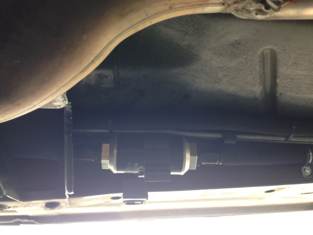
Also, there was so questions about the rest of the fuel system. I removed the stock feed line, the short return line from the filter to the tank, and the stock rails. I used Holley fuel rails, filter, and regulator. There wasn't enough room in the stock filter location, so i moved the filter inside the frame rail behind the trans crossmember. The brake and evap lines needed to be moved so they stack horizontally, but it can be pretty easily done. Also, where the lines pass the headers/ cats, I used a heat shield jacket to protect the lines. Here is a pic of the filter
09-09-2013, 10:47 PM
#19
Could you explain your wiring?
Why do you have the stock connector connected to the bucket? I don't see it plugged into a hotwire kit either - it shouldn't be powering anything inside the bucket. Do you have it spliced downstream feeding into your relays? Also did you take power from the alternator or battery?
Why do you have the stock connector connected to the bucket? I don't see it plugged into a hotwire kit either - it shouldn't be powering anything inside the bucket. Do you have it spliced downstream feeding into your relays? Also did you take power from the alternator or battery?
09-10-2013, 04:05 PM
#20
On The Tree
Thread Starter
iTrader: (14)
Join Date: Jan 2005
Location: St. Louis, MO
Posts: 151
Likes: 0
Received 0 Likes
on
0 Posts
The stock connector on top of the bucket also has the fuel level wiring, which is why it remains. I removed the stock pump wiring by removing the pin from the connector at the rear of the tank, and left the rest of the wiring to the tank. That factory wiring energizes a relay, which is fed straight from the battery (or alt or starter). The second pump will be triggered by either a Hobbs switch or when the nitrous is armed (whichever route I go)