
8.8 rear end vibration
 04-12-2016, 05:40 PM
#181
But the block should work on either diff. Only real difference is the clearance on the right rear of it for the support that the iron housing has which the aluminum does not.
 04-13-2016, 02:23 PM
#182
Please report on any noise difference as well. I put the block in when I did the 8.8 so I don't have a frame of reference. I have noise on decel (yeah I know pinion preload) and have had it since I installed the 8.8. Even though you would think the noise from the block would be worse on accel, I have begun to wonder if it is the block vice the pinion...


 in the rear
  04-17-2016, 07:30 PM
#188
On The Tree
iTrader: (3)

Join Date: Jun 2006
Location: Central Floriduh
Posts: 102
Likes: 0
Received 0 Likes
on
0 Posts

Put a third subframe washer in today, all it accomplished was pushing the driveshaft into the exhaust. No change in vibration. Has anyone had any luck with the laser CS tool?
04-17-2016, 08:06 PM
#189
TECH Addict
iTrader: (19)
Join Date: Aug 2007
Location: Where the Navy tells me to go
Posts: 2,407
Received 107 Likes
on
89 Posts
I have the CS tool right now, and used it yesterday. Had to push my trans cross-member a little bit to the passenger side to get the output to be pointing at the input of the diff. I didn't worry about vertical alignment, just wanted to make sure everything was in line. Unfortunately, it didn't fix my vibration issue, but I think I've narrowed down where the problem lies; more on that later when I have time to type up a real post.
04-19-2016, 12:23 AM
#192
TECH Resident

Join Date: Aug 2010
Posts: 756
Likes: 0
Received 0 Likes
on
0 Posts
04-19-2016, 02:53 AM
#194
TECH Resident
Join Date: Aug 2010
Posts: 756
Likes: 0
Received 0 Likes
on
0 Posts

Optimal dss angles that's trans output shaft to ds and pinion flange to ds
5 Things can cause vibrations
1.Tires (we are gonna pretend that it's not the case here)
2. Drive shaft being out of phase (rotate your driveshaft and see if it changes anything, has been a common issue even with stock parts on our platform.
3. Ds angles should be close to 2 degrees. You want the diff to be pointing 2 degrees down when power is applied it will want to move up causing the angles to get closer to 0.
4. Gears in the transmission. Make sure your speed vibes are not gear specific. Our t56s are notorious for having vibes in 5th and 6th gear.
5. Your rear end was not setup properly so now you will have noise or vibration on deceleration or acceleration.
04-20-2016, 11:38 PM
#195
TECH Addict
iTrader: (19)
Join Date: Aug 2007
Location: Where the Navy tells me to go
Posts: 2,407
Received 107 Likes
on
89 Posts
Had my car up on the lift again over the weekend. Pulled the exhaust so I could get to the driveshaft and do some more checking. My intentions were to check the position of the carrier bearing with the driveshaft bolted directly to the tranny output (no flex disk in the equation), as recommended by voodoochikin, and to check the alignment of the engine and diff with Creative Steel's laser alignment tool.
First, even with the shorter CS driveshaft adapter, the driveshaft is still a very tight fit. To get it out, I had to take up all of the compression "slack" in the 2 CVs, which just allowed me to start getting the rear CV to come down out of the adapter. However, there was still pretty heavy interference between the CV and the adapter, to the point that as the rear face of the CV (which is domed / convex) was coming free from the adapter, a couple of high points on the adapter were scraping that domed face. I'm doing a poor job describing the interference - here's what it looked like as I was trying to get it to come out:
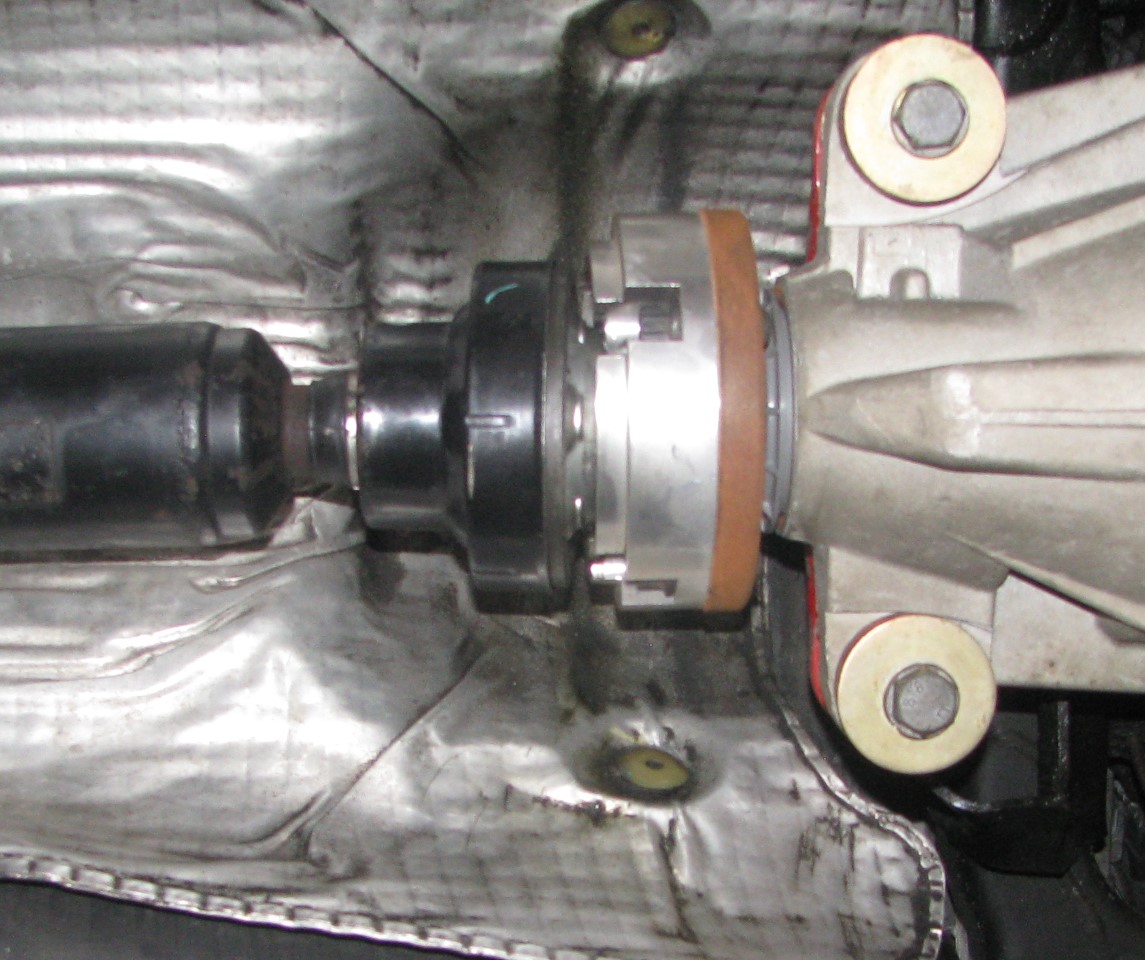
You can see the CV isn't clear of the raised lip on the adapter. I had to turn the pinion flange to get one of the bolt hole gaps at 6 o'clock, and then pull the driveshaft down through that gap (with the two edges of the gap scraaaaaping their way across the CV. To get the driveshaft back in, I bolted up the forward end of the driveshaft, then shoved the rear of the shaft forward (to again take up all of the available compression movement in the CVs) to get the rear CV started into the adapter, and had to use a mallet to tap it into place.
Once I had the driveshaft out I pulled off the flex disk, then put the driveshaft back in place and bolted it directly to the tranny output. Well, as directly as you can - with the ~1" nub that sticks out of the output flange, and the corresponding nub on the front of the driveshaft, you can't really bolt them together directly. Knowing that, I had picked up some 1/2" close pipe nipples (which are a bit over 1" long) to use as spacers.
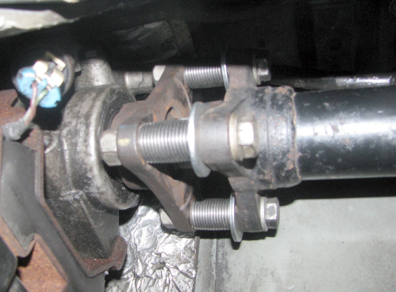
I put a couple bolts into the rear CV to hold the rear of the driveshaft in position on the pinion flange adapter. At first it appeared the carrier bearing was being driven up into the top of the driveshaft tunnel, so I thought maybe the engine mounts needed to be bumped up a bit. But then I rotated the driveshaft and found that the carrier bearing would move up/down/side-to-side as I rotated the driveshaft.
As stated at the end of the video, that uneven motion could be due to a number of things. I mentioned the spacers might not be even, or that the transmission output could be bent. The other possibility is that the input flange on the driveshaft isn't square to the driveshaft.
I knew the pipe nipples weren't perfect, so I had spent some time with a Dremel and bench grinder trying to even them up as best I could. However, after shooting the video, I measured the space between the trans and driveshaft flanges at the 3 legs and they weren't the same. So I pulled the pipe nipples out and bolted the flanges back together without any spacers in there, and tightened the 3 bolts to get the 3 measurements to match. I still saw the same movement of the carrier bearing as I rotated the driveshaft.
I didn't really have any way to check the runout of the transmission output flange. I did put a straight edge off the top of the tranny mount, and checked the 3 legs all cleared that straight edge by the same amount as I rotated the output flange, but that's not really a useful check. That maybe gets me 60deg of the 360deg rotation, so I have no idea what the flange is doing for the other 300deg. And with the tools and equipment I had on hand I had no way to check whether the input flange on the driveshaft is square to the shaft. I had to get the car back together, so I didn't really resolve anything.
The way I see it there are 3 options:
(1) My test was invalid. Despite getting the flanges as parallel as I could (using vernier calipers to measure), perhaps it wasn't good enough.
(2) There's runout in the transmission output. I never noted this with the stock carrier bearing because the driveshaft was able to wobble around in the mushy rubber bushing around the carrier.
(3) The input flange of the refurbished driveshaft isn't square to the shaft, resulting in the vibration. I'm not particularly sure how to determine if that's the case or not.
First, even with the shorter CS driveshaft adapter, the driveshaft is still a very tight fit. To get it out, I had to take up all of the compression "slack" in the 2 CVs, which just allowed me to start getting the rear CV to come down out of the adapter. However, there was still pretty heavy interference between the CV and the adapter, to the point that as the rear face of the CV (which is domed / convex) was coming free from the adapter, a couple of high points on the adapter were scraping that domed face. I'm doing a poor job describing the interference - here's what it looked like as I was trying to get it to come out:
You can see the CV isn't clear of the raised lip on the adapter. I had to turn the pinion flange to get one of the bolt hole gaps at 6 o'clock, and then pull the driveshaft down through that gap (with the two edges of the gap scraaaaaping their way across the CV. To get the driveshaft back in, I bolted up the forward end of the driveshaft, then shoved the rear of the shaft forward (to again take up all of the available compression movement in the CVs) to get the rear CV started into the adapter, and had to use a mallet to tap it into place.
Once I had the driveshaft out I pulled off the flex disk, then put the driveshaft back in place and bolted it directly to the tranny output. Well, as directly as you can - with the ~1" nub that sticks out of the output flange, and the corresponding nub on the front of the driveshaft, you can't really bolt them together directly. Knowing that, I had picked up some 1/2" close pipe nipples (which are a bit over 1" long) to use as spacers.
I put a couple bolts into the rear CV to hold the rear of the driveshaft in position on the pinion flange adapter. At first it appeared the carrier bearing was being driven up into the top of the driveshaft tunnel, so I thought maybe the engine mounts needed to be bumped up a bit. But then I rotated the driveshaft and found that the carrier bearing would move up/down/side-to-side as I rotated the driveshaft.
As stated at the end of the video, that uneven motion could be due to a number of things. I mentioned the spacers might not be even, or that the transmission output could be bent. The other possibility is that the input flange on the driveshaft isn't square to the driveshaft.
I knew the pipe nipples weren't perfect, so I had spent some time with a Dremel and bench grinder trying to even them up as best I could. However, after shooting the video, I measured the space between the trans and driveshaft flanges at the 3 legs and they weren't the same. So I pulled the pipe nipples out and bolted the flanges back together without any spacers in there, and tightened the 3 bolts to get the 3 measurements to match. I still saw the same movement of the carrier bearing as I rotated the driveshaft.
I didn't really have any way to check the runout of the transmission output flange. I did put a straight edge off the top of the tranny mount, and checked the 3 legs all cleared that straight edge by the same amount as I rotated the output flange, but that's not really a useful check. That maybe gets me 60deg of the 360deg rotation, so I have no idea what the flange is doing for the other 300deg. And with the tools and equipment I had on hand I had no way to check whether the input flange on the driveshaft is square to the shaft. I had to get the car back together, so I didn't really resolve anything.
The way I see it there are 3 options:
(1) My test was invalid. Despite getting the flanges as parallel as I could (using vernier calipers to measure), perhaps it wasn't good enough.
(2) There's runout in the transmission output. I never noted this with the stock carrier bearing because the driveshaft was able to wobble around in the mushy rubber bushing around the carrier.
(3) The input flange of the refurbished driveshaft isn't square to the shaft, resulting in the vibration. I'm not particularly sure how to determine if that's the case or not.
04-21-2016, 07:26 AM
#196
Dude, that video is seriously messed up. No wonder you're getting vibes.
I like the "bolt the shaft down tight" theroy of aligning the shaft but instead of using spacers, I took all 6 bolts out of the flex disc, rotated the driveshaft until it lined up with the output shaft and bolted them together through the flex disc. Seemed to work and I didn't have to pull it apart to do it.
The one piece comes with adapters, one of which bolts to the transmission. This gave me a flat surface to check output shaft runout and I got 3 to 5 thousands if I remember correctly. What we don't know is what is a reasonable tolerance for this and how this little bit of runout would affect the front part of the driveshaft. I will say this, the car is finally smooth with the one piece on the 8.8 so if the flange is an issue, the 1 pieces CV joint is compensating for it. Who knows but I tend to look towards what GM has done to address these concerns and if you look at the V2 tr6060, you'll see that the output flange is a full CV "cup" that has 6 bolts firmly mating and indexing it all together...if there wasn't an improvement to be had, why would you change it.
As a compromise, you could probably take runouts at the front and rear of the front part of the shaft to get some indication of how bad the output flange is. If the output flange "fingers" aren't straight, you could expect the runouts to increase as you go down the shaft (stop what you're thinking) but they all should be on the same line running the length of the shaft. If the runouts vary along the length of the shaft from 9 o'clock to say 1 o'clock, then the shaft is bent or twisted.
As far as how the 2 pieces of the shaft mate together, I'll assume there is a splined interface between the 2 so It'd be hard to get that wrong unless it gets bent. I haven't had one apart so I can't say.
IMHO, the driveshaft is still too tight. The CVs have to have some ability to move in order to work properly and I'm beginning to firmly believe that the joints should be installed as close as possible to their relaxed state to function. From what I can tell, this would be at the half way point of their total travel and its safe to say you're CVs aren't anywhere near this....could they be bottoming out as the shaft rotates?? As tight as they are, I don't see how they can do what they're designed to do which is to compensate for angular irregularity and maybe even runout.
Thanks for posting all of this.
EDIT: If you bolt the carrier bearing down tight, I imagine (i'd hope anyway) all of this movement would be compensated for by the flex disc. How much of it is anybody's guess.
Last edited by ls1247; 04-21-2016 at 07:39 AM.
04-21-2016, 10:00 PM
#197
TECH Addict
iTrader: (19)
Join Date: Aug 2007
Location: Where the Navy tells me to go
Posts: 2,407
Received 107 Likes
on
89 Posts
I like the "bolt the shaft down tight" theory of aligning the shaft but instead of using spacers, I took all 6 bolts out of the flex disc, rotated the driveshaft until it lined up with the output shaft and bolted them together through the flex disc. Seemed to work and I didn't have to pull it apart to do it.

IMHO, the driveshaft is still too tight. The CVs have to have some ability to move in order to work properly and I'm beginning to firmly believe that the joints should be installed as close as possible to their relaxed state to function. From what I can tell, this would be at the half way point of their total travel and its safe to say your CVs aren't anywhere near this....could they be bottoming out as the shaft rotates?? As tight as they are, I don't see how they can do what they're designed to do which is to compensate for angular irregularity and maybe even runout.
04-21-2016, 10:18 PM
#198
That's an insane amount of movement. For comparison, here's the OEM driveshaft with sagging carrier spinning, from several different angles:
In these videos, I'm running the hard 75D Revshift guibo, so if there were any runout issues, they'd be very apparent in the above clips.
In these videos, I'm running the hard 75D Revshift guibo, so if there were any runout issues, they'd be very apparent in the above clips.
04-22-2016, 08:29 AM
#200
I know when you aligned it earlier in the thread, the driveshaft seemed to favor one side of the car and I guess that would be true for about 90 degrees of revolution. The other 270 degrees, its somewhere else.
Guess in the meantime you need to find the effective center of all this movement and lock the carrier bearing down there.
Where do you go from here?