
LS2 into 99 Mustang
 10-01-2009, 10:35 AM
#21
Teching In
Join Date: Sep 2009
Posts: 43
Likes: 0
Received 0 Likes
on
0 Posts
But the fox didn't have sequential injection. That means you need a trigger on the cam. With the LS1 that was a no-go but with the LS2 and LS3 GM put the sensor on the timing cover. Bingo! I reused the hole and milled an adapter to mount the Ford sensor. For the crank sensor I used a 36-1 teeth trigger wheel from Ebay. Common part for those that use Megasquirt. The key is knowing how to time the triggers...
 10-01-2009, 11:05 AM
#22
On The Tree
Thread Starter
iTrader: (2)

Join Date: Mar 2005
Location: Detroit
Posts: 182
Likes: 0
Received 0 Likes
on
0 Posts

So there is no way to use the gm sensor then? I looked at one the other day and did notice it is 3 wires, but considering what it reads (1 single bump on the front face of the timing gear) it has to be a vr sensor. Do you think you could make a couple extra adapters?
GM sensors: Hall effect (square wave)
Two totally different animals.
A few months ago I had planned a little kit that I could sell but given the complexity and the cost involved I gave up. I think most people would simply retrofit all the GM stuff and call it a day. I can make my own parts so my cost is low. Just a lot of hours machining parts. The cam sensor adapter I made out of a 4" billet and it took me 3 hours to make on a lathe. It's just not cost effective to sell this stuff.
10-01-2009, 12:01 PM
#23
Staging Lane
iTrader: (3)

Join Date: Feb 2003
Location: WACO
Posts: 99
Likes: 0
Received 0 Likes
on
0 Posts
Ford cam and crank sensors: Variable reluctance (sine wave)
GM sensors: Hall effect (square wave)
Two totally different animals.
A few months ago I had planned a little kit that I could sell but given the complexity and the cost involved I gave up. I think most people would simply retrofit all the GM stuff and call it a day. I can make my own parts so my cost is low. Just a lot of hours machining parts. The cam sensor adapter I made out of a 4" billet and it took me 3 hours to make on a lathe. It's just not cost effective to sell this stuff.
10-01-2009, 02:04 PM
#24
Teching In
Join Date: Sep 2009
Posts: 43
Likes: 0
Received 0 Likes
on
0 Posts
I am also very interested in this adapter. The only other way to get a vr signal off the cam would be to intall the distributor conversion timing cover and use a stub shaft from an explorer 5.0. And I think that would suck.
Waiting patiently to see the progress pics.
(Too bad we don't have that smiley eating popcorn on here.)
Waiting patiently to see the progress pics.
(Too bad we don't have that smiley eating popcorn on here.)
10-03-2009, 01:47 PM
#25
On The Tree
Thread Starter
iTrader: (2)
Join Date: Mar 2005
Location: Detroit
Posts: 182
Likes: 0
Received 0 Likes
on
0 Posts
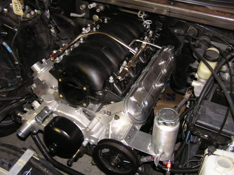
Here are some updates to my project.
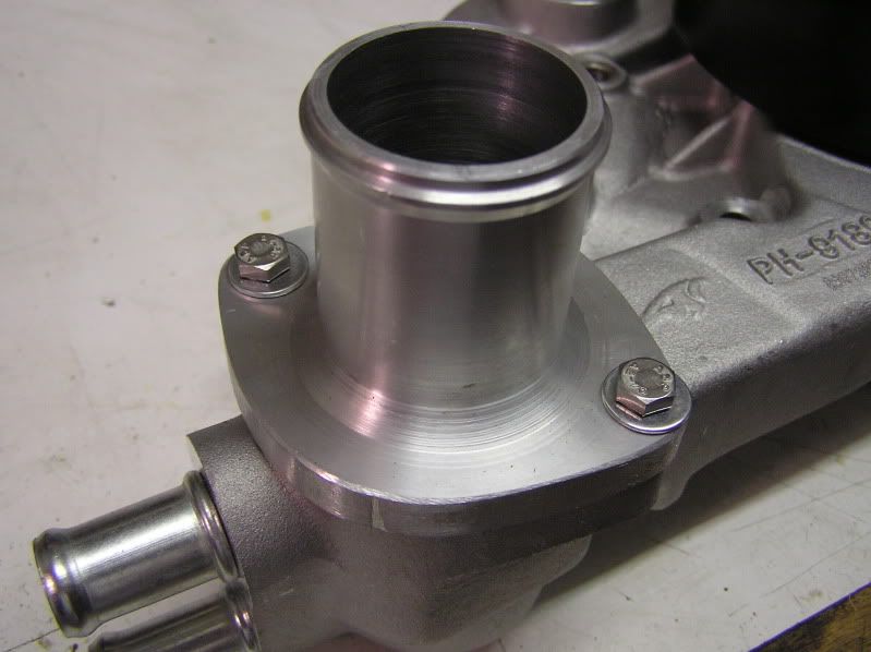
1-3/4" straight thermostat housing. Started with a 4" billet and milled it down.
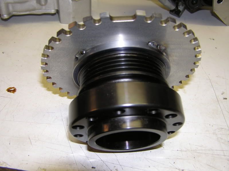
Crank shaft trigger wheel. 36-1 teeth. That's a typical part used in a Megasquirt kit. I got this one from trigger wheels dot com. 5mm thick, laser cut. I milled the center to fit on a ATI hub (F-body accessory drive) and spaced it back a little. My plan is to run a dry sump and the 4 rib pulley is where the belt rides to run the scavenge pump. Keeping the factory pressure pump. This setup is standard in road racing. The wheel could be adapted to any GM harmonic balancer. The crank will need an extra keyway to prevent the hub from slipping. the missing tooth must be timed correctly for the ignition to work.
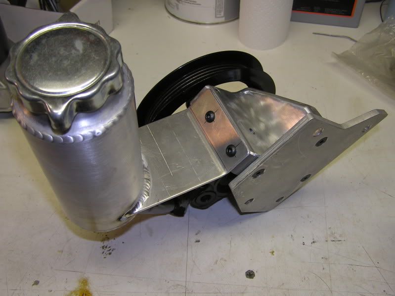
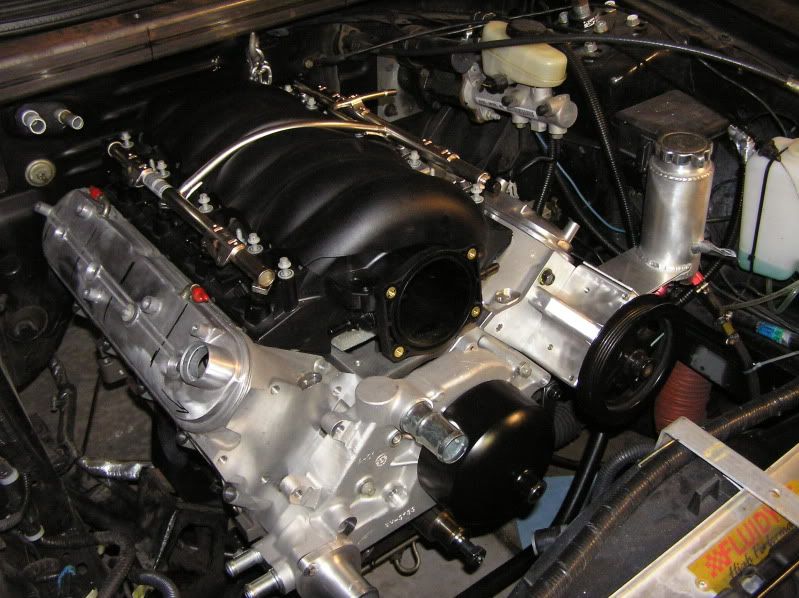
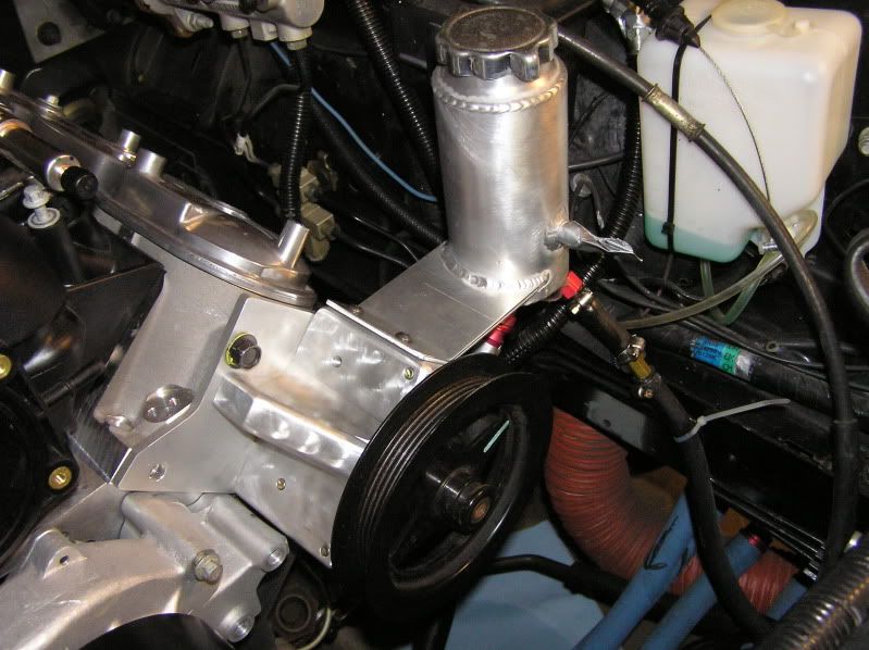
Ford Modular power steering pump and oval track reservoir. I had to make an adapter bracket (big chunk of aluminum) to mount to the head. I will take weight out of the bracket when I get a few minutes. The next picture shows where it goes.
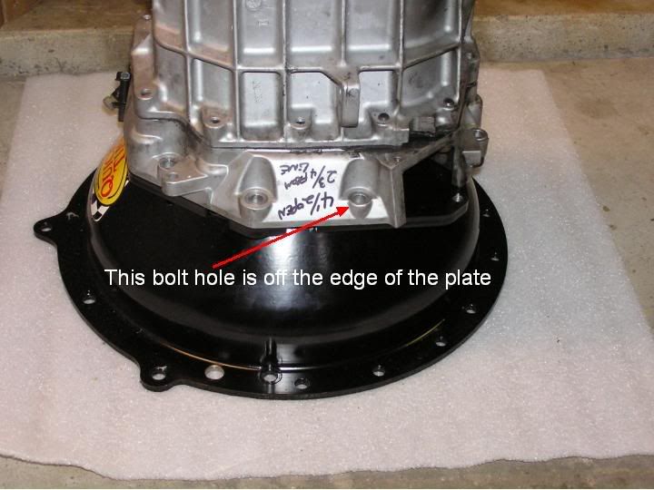
'03 Cobra T56 with LS1/T56 bellhousing (Quicktime RM8020)
There is one bolt that is off the edge of the mounting plate. I'll mill the plate and extend it to use that bolt (just above the fork opening). The bolt in the middle of the opening will not be used. The rest of the bolts all line-up. I will keep the factory cable system. I will cut the window I need for the fork. The mounting plate is 1/2" thick steel. Quicktime wasn't kidding when they designed it. The rest of the housing is spun steel. Very well done.
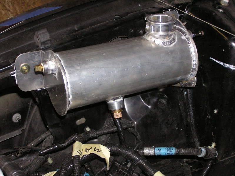
Overflow tank. Fabricated with 4" tubing (I'll use it for the cold air intake also) and 1/8" plates on the end. The plugs are still shown from when I pressure tested it.
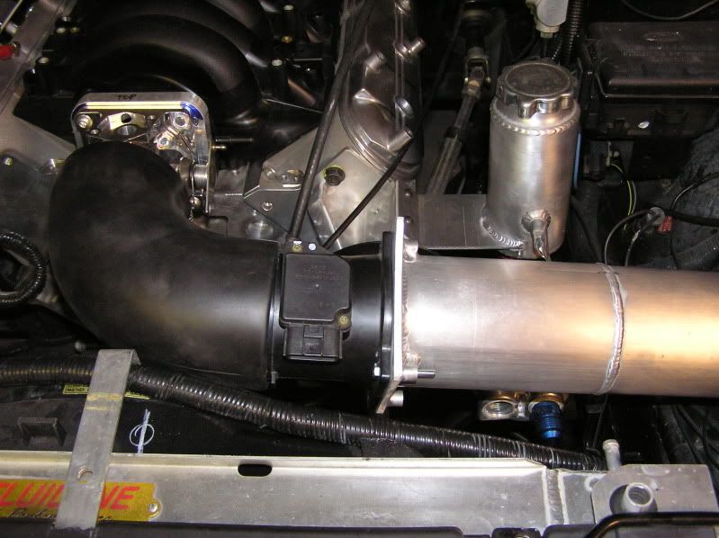
Cold air intake and Lightning 90mm MAF. I just finished it this past week.
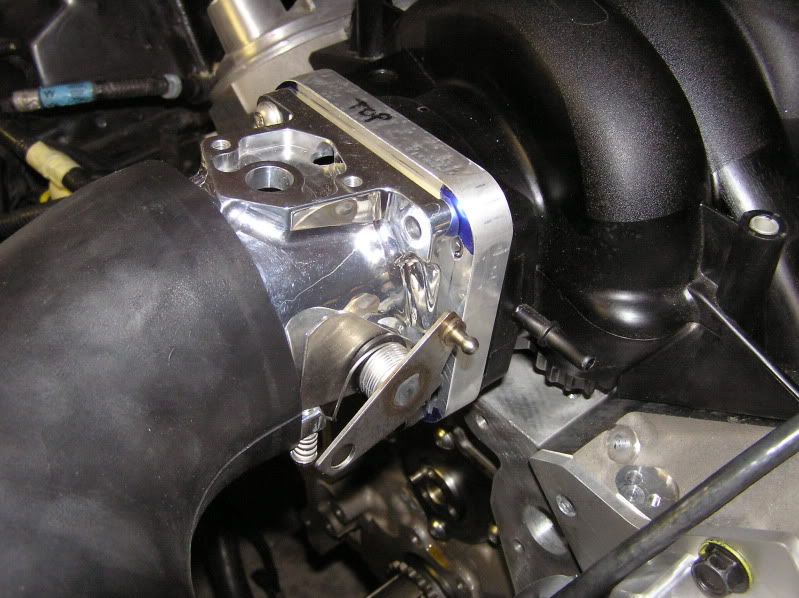
Accufab 90mm throtle body for a fox mustang. Allows me to use a compatible TPS and IAC. the GM stuff is not compatible. I had to mill a 3/4" adapter plate. The 4" hole in the plate was rough cut with a hole saw and finished with a boring bar on a Bridgeport.
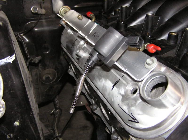
Modular coil on plug. I press breaked an aluminum bracket to mount the coils. I will buy universal ignition wire and crimp it inside the spring. Voila! coil near plug.
Cam sensor. Escort ZX2 sensor mounted to an adapter. The MOD sensors are too big.
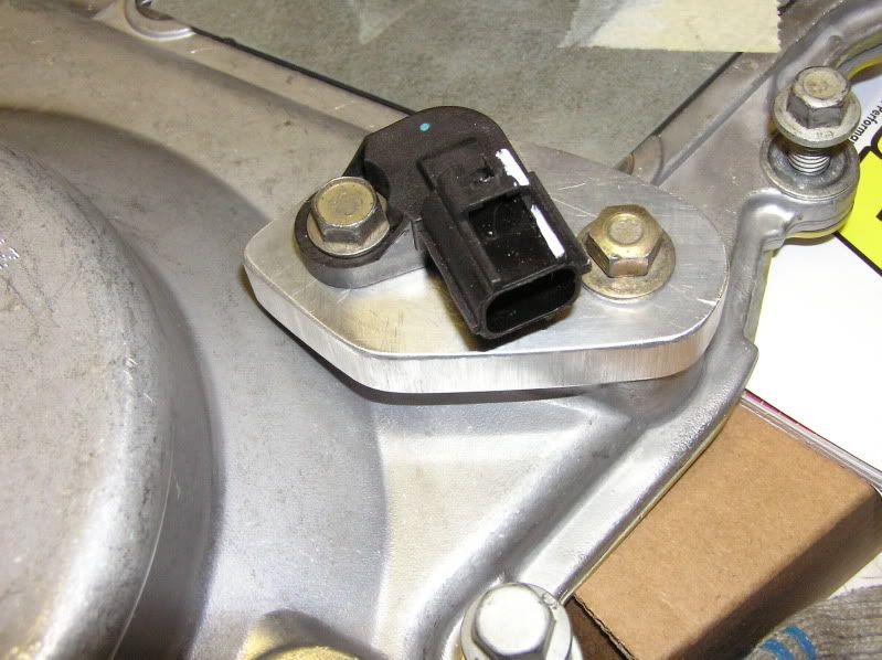
Ford's cylinder #1 is Chevy's #2. The firing pattern is the same.
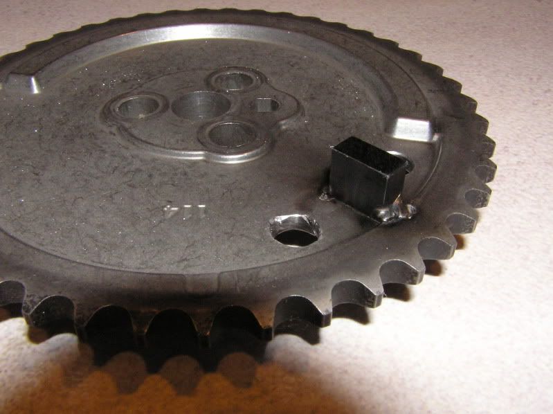
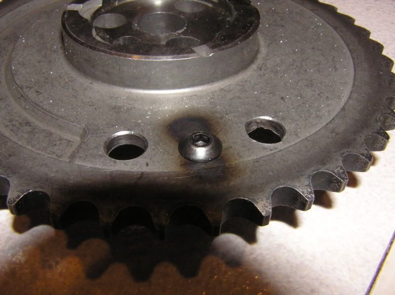
I modified the cam sprocket also with a trigger. I'll post it when I have a few minutes.
1-3/4" straight thermostat housing. Started with a 4" billet and milled it down.
Crank shaft trigger wheel. 36-1 teeth. That's a typical part used in a Megasquirt kit. I got this one from trigger wheels dot com. 5mm thick, laser cut. I milled the center to fit on a ATI hub (F-body accessory drive) and spaced it back a little. My plan is to run a dry sump and the 4 rib pulley is where the belt rides to run the scavenge pump. Keeping the factory pressure pump. This setup is standard in road racing. The wheel could be adapted to any GM harmonic balancer. The crank will need an extra keyway to prevent the hub from slipping. the missing tooth must be timed correctly for the ignition to work.
Ford Modular power steering pump and oval track reservoir. I had to make an adapter bracket (big chunk of aluminum) to mount to the head. I will take weight out of the bracket when I get a few minutes. The next picture shows where it goes.
'03 Cobra T56 with LS1/T56 bellhousing (Quicktime RM8020)
There is one bolt that is off the edge of the mounting plate. I'll mill the plate and extend it to use that bolt (just above the fork opening). The bolt in the middle of the opening will not be used. The rest of the bolts all line-up. I will keep the factory cable system. I will cut the window I need for the fork. The mounting plate is 1/2" thick steel. Quicktime wasn't kidding when they designed it. The rest of the housing is spun steel. Very well done.
Overflow tank. Fabricated with 4" tubing (I'll use it for the cold air intake also) and 1/8" plates on the end. The plugs are still shown from when I pressure tested it.
Cold air intake and Lightning 90mm MAF. I just finished it this past week.
Accufab 90mm throtle body for a fox mustang. Allows me to use a compatible TPS and IAC. the GM stuff is not compatible. I had to mill a 3/4" adapter plate. The 4" hole in the plate was rough cut with a hole saw and finished with a boring bar on a Bridgeport.
Modular coil on plug. I press breaked an aluminum bracket to mount the coils. I will buy universal ignition wire and crimp it inside the spring. Voila! coil near plug.
Cam sensor. Escort ZX2 sensor mounted to an adapter. The MOD sensors are too big.
Ford's cylinder #1 is Chevy's #2. The firing pattern is the same.
I modified the cam sprocket also with a trigger. I'll post it when I have a few minutes.
Last edited by serpentnoir; 10-03-2009 at 08:14 PM.
10-03-2009, 07:40 PM
#26
On The Tree
Thread Starter
iTrader: (2)
Join Date: Mar 2005
Location: Detroit
Posts: 182
Likes: 0
Received 0 Likes
on
0 Posts
The cam trigger. Kind of crude but it's job is simple. GM's factory gear is sintered metal. It doesn't weld or drill easily. The welds are just added insurance. I bolted the trigger with a #10 screw and some red Loctite. It's not going anywhere. If funds allow I may switch to a billet gear and redo the trigger. I am more or less happy with it.
Aeromotive makes an adapter for the fuel pressure sensor. I cut-off the end of the fuel rail, milled a stainless -6AN fitting and welded it. I will hook up a short length of braided hose from here to the sensor.
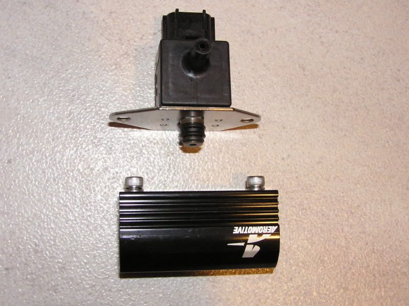
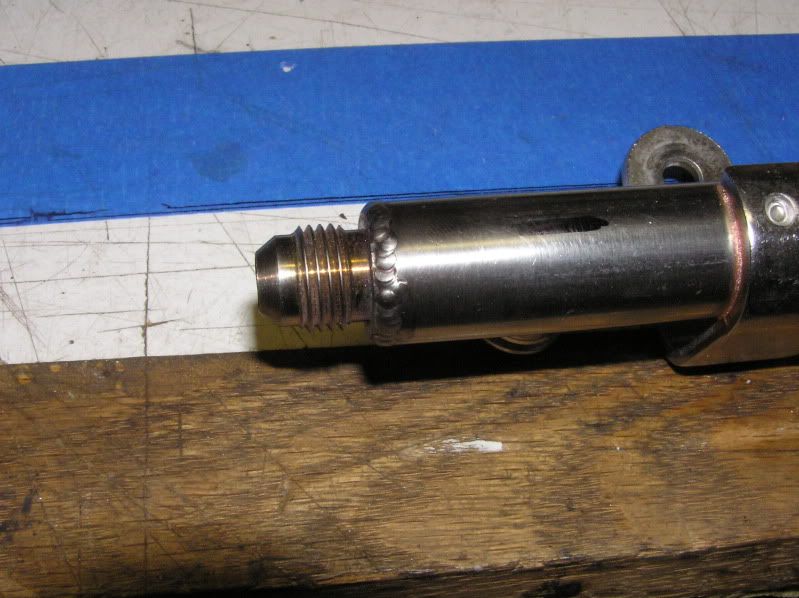
Aeromotive makes an adapter for the fuel pressure sensor. I cut-off the end of the fuel rail, milled a stainless -6AN fitting and welded it. I will hook up a short length of braided hose from here to the sensor.
10-03-2009, 07:48 PM
#27
On The Tree
Thread Starter
iTrader: (2)
Join Date: Mar 2005
Location: Detroit
Posts: 182
Likes: 0
Received 0 Likes
on
0 Posts
Everyone seems to complain about the fitment of headers. I'm thinking of getting a kit and making my own. I want mid-lengths anyway. Long tubes are a PITA anyway.
10-05-2009, 11:20 AM
#28
Teching In
Join Date: Sep 2009
Posts: 43
Likes: 0
Received 0 Likes
on
0 Posts
This build is looking great man! I am so glad to see someone else interested in this conversion. I never thought of adding a piece of metal to the cam gear. There is another design cam gear that has 3 or 4 bumps on it. I always thought one might be close enough to work, and the others could be ground off. By the placement of yours though, I think your way is the only way on that. I hope adding wires to those coils works out. That kinda makes me nervous.
Keep us posted!
Keep us posted!

 10-05-2009, 12:04 PM
#30
On The Tree
Thread Starter
iTrader: (2)
Join Date: Mar 2005
Location: Detroit
Posts: 182
Likes: 0
Received 0 Likes
on
0 Posts
My original thought was also to grind the bumps down but when I got the gear I realized it was made of sintered metal and the bumps go "in" on the back side. So if you mill them down you blow through the gear. GM did that to keep the balance on the gear and maintain even thickness. I drilled two holes to compensate for the added weight of the tab. It's not pretty but it should work. Centrifugal force is the only concern. The tab does not touch anything. I'm just lucky the tab didn't end up on the end of the GM bump or on it.
I studied the Comp billet gear also. They drilled holes to re-balance the gear. I may use it and re-do this gear. Billet can be welded properly. I just wish someone would sell me a plain/solid gear and I could modify as needed.
The COP is an area of low risk. Other areas worry me more (i.e. cam trigger, cable clutch, IAC)
Last edited by serpentnoir; 10-05-2009 at 12:10 PM.

 10-20-2009, 10:36 AM
#34
Teching In
Join Date: Sep 2009
Posts: 43
Likes: 0
Received 0 Likes
on
0 Posts
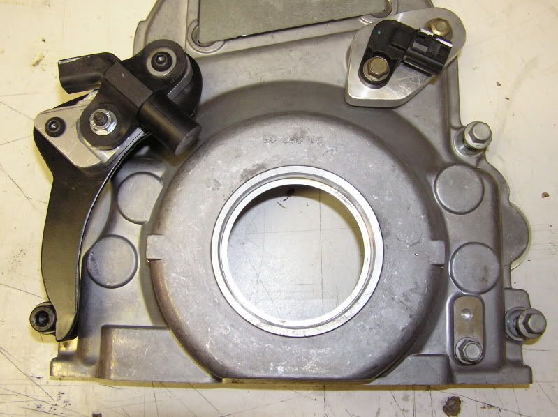
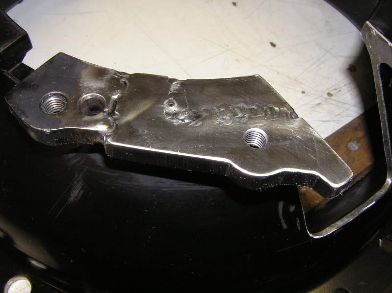
Wow that mount looks tough! I would have been tempted to make a smaller, cheesier one off of that boss on the right side of the photo.
So, why is this bitch not on the road?? Wheres the nasty burn out video??
So, why is this bitch not on the road?? Wheres the nasty burn out video??
10-20-2009, 11:22 AM
#35
On The Tree
Thread Starter
iTrader: (2)
Join Date: Mar 2005
Location: Detroit
Posts: 182
Likes: 0
Received 0 Likes
on
0 Posts
I want it on the road more than anyone else. Still a lot of work to do: motor not built yet, T56 trans is junk and has to be completely rebuilt. Need headers and the list goes on.
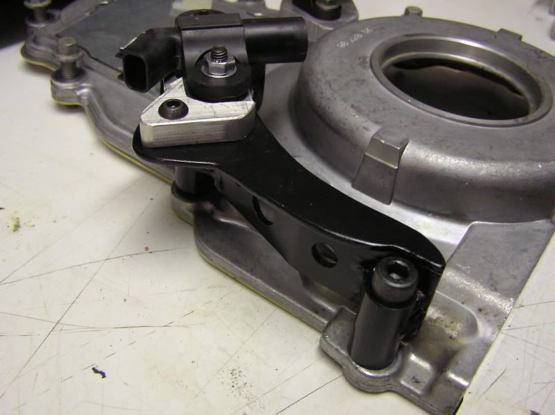
The bracket is beefy because I don't want the sensor to vibrate. The cover is too thin to drill and tap.
The bracket is beefy because I don't want the sensor to vibrate. The cover is too thin to drill and tap.
10-20-2009, 08:57 PM
#37
On The Tree
Thread Starter
iTrader: (2)
Join Date: Mar 2005
Location: Detroit
Posts: 182
Likes: 0
Received 0 Likes
on
0 Posts
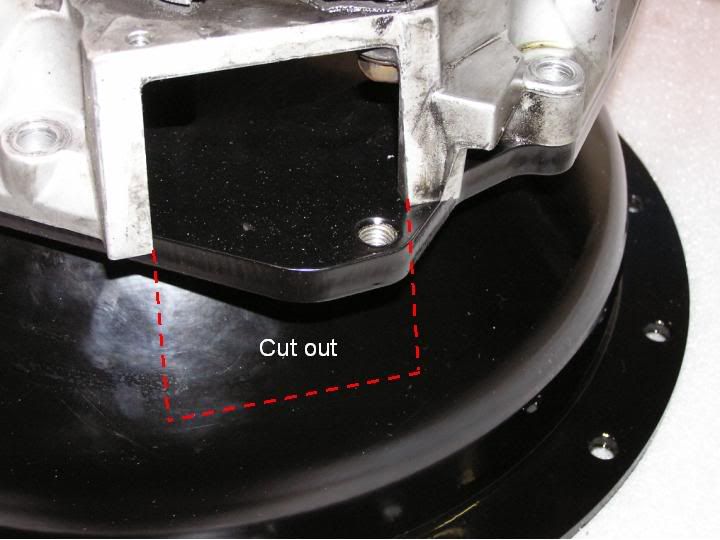
I finished the mods on the bellhousing. This started out as a Quicktime LS1 to T56 trans bellhousing. I am mating it to a Ford '03 T56 Cobra trans. The two dowel pins and all the holes lined up except for one. I milled the adapter plate back, cut an insert, welded it in and drill\tap the missing hole. To the right is the window I cut out for the clutch fork.
I got this idea from a conversation with Jam Performance Transmission. They do something similar but the price tag was a little out of my budget...
In my opinion, Quicktime should offer something like that. There should be enough of a market for it.
I got this idea from a conversation with Jam Performance Transmission. They do something similar but the price tag was a little out of my budget...
In my opinion, Quicktime should offer something like that. There should be enough of a market for it.

 10-21-2009, 07:13 PM
#40
On The Tree
Thread Starter
iTrader: (2)
Join Date: Mar 2005
Location: Detroit
Posts: 182
Likes: 0
Received 0 Likes
on
0 Posts
I am not 100% sure if it will work but I will try. The trans should only need a Camaro 26 input shaft. The clutch is a mystery. I will try a F-body clutch with a Ford throwout bearing.