

How does 04 GTO PCM turn on A/C
 04-17-2010, 06:38 PM
#1
TECH Apprentice
Thread Starter
iTrader: (4)

Join Date: Dec 2008
Location: Broken Arrow, OK
Posts: 317
Likes: 0
Received 0 Likes
on
0 Posts
Ok, I trying to build my A/C system for my 97 240sx with a L33 and T56. I'm running a 04 GTO PCM and a 04 GTO A/C compressor. I plan on having a local A/C shop build some A/C lines for me and install the LS pressure sensor.
Does anyone know if the A/C pressure sensor and dryer are the same for the LS and V6 Camaros???
I found some instructions for intergrating the S14 system with the Camaro/Vette A/C system, but from what we've gathered the GTO system is diffrent. Here are some notes: Courtsey of twistedsymphony on Silviav8froums
I just went though the wiring for AC on the Vette and the Camaro into an S14... it's actually pretty simple.
this is a repost from my article here: http://tech.240sxone.com/300/ls1-ac-wiring/
The HVAC electrical diagrams for the S14 span 6 pages, the Vette diagram doesn't even fill 1.
Components needed
-LS AC compressor (duh)
-LS AC Pressure Sensor (might want to get the line it attaches to as well)
-An AC Relay (the Factory Relay in your S-chassis will do just fine)
-Your ECU needs to be programmed for a "Manual HVAC" setup (not "Automatic")
This wiring should work for engines sourced from LS1 equipped Corvettes, Camaros, and Firebirds.
1. AC Compressor has 2 pins: One for 12V and one for ground, this is switched on by the Relay. What you're doing here is simply cutting off the S14 AC connector ( on the drivers side near the steering rack) re-routing to the right side of the bay and soldering on the LS connector.
-Pin A on the LS connector is Dark Green and replaces Pin 1 on the S14 Compressor Connector E46 which is Yellow with a Red Stripe (switched 12V source)
-Pin B on the LS connector is Black and replaces Pin 2 on the S14 Compressor Connector E46 (ground)
2. AC Pressure Sensor has 3 pins, a ground reference, a 5V reference and an output signal, all 3 feed directly into the LS harness and directly to the ECU
-Pin A on the LS connector for the Corvette it is Black and goes to Blue#60 on the ECU harness, for the F-Body it is Purple and goes to Red#57 on the ECU harness (Ground Reference)
-Pin B on the LS connector is Gray and goes to Blue#45 on the ECU harness (5V Reference)
-Pin C on the LS connector is Red with a Black Stripe and goes to Red#14 on the ECU harness (Sensor Signal)
3.There are a few connections at the F3 plug, allowing easy integration with the S14 for turning on/off ac F3 pins are based on the diagram here: http://forums.240sxone.com/showthread.php?t=7091
-Pin 32 on the F3 connector is Yellow with A Black stripe and goes to Red#17 on the ECU which is Dark Green with a White stripe (AC On signal from HVAC)
-Pin 43 on the F3 connector is Black with a Pink stripe and goes to Red#43 on the ECU harness which is Dark Green with a White stripe (Compressor Relay turn on signal)
-Pin 44 on the F3 connector is Blue with a Red stripe and goes to Red#18 on the ECU harness which is Dark Green (AC Clutch Status)
4.The Triple pressure switch found on the S14 Dryer isn't needed for the LS AC setup so it needs to be bypassed, this is located near the battery tray.
-S14 connector E29 Jump pin 1 (Black with pink Stripe) to pin 4 (Green with Yellow Stripe), the other 2 pins can be left as is, one goes to the F3 plug and isn't used, the other goes to ground
*Note: there are about a dozen other AC related pins on the F3 plug, none of these are needed so you can just de-pin them to clean up the plug.
EDIT:
FWIW I just checked the 2004 LS1 equipped GTO and it's the same as the Camaro except for the AC request signal... it seems like that is handled by the body control module... I'm not sure exactly how it tells the the ECU to turn the AC on.
 04-17-2010, 09:46 PM
#2

PCM
Red Connector
Pin
14 A/C Refrigerant Pressure Sensor Signal
18 A/C Compressor Clutch Supply Voltage
43 A/C Clutch Relay Control
57 Low Reference - IAT Sensor and A/C Refrigerant Pressure Sensor
BCM
Connector C1
Pin
19 A/C Request Signal
Grant did you ever send my stuff back?
Red Connector
Pin
14 A/C Refrigerant Pressure Sensor Signal
18 A/C Compressor Clutch Supply Voltage
43 A/C Clutch Relay Control
57 Low Reference - IAT Sensor and A/C Refrigerant Pressure Sensor
BCM
Connector C1
Pin
19 A/C Request Signal
Grant did you ever send my stuff back?
04-17-2010, 10:24 PM
#3
TECH Apprentice
Thread Starter
iTrader: (4)
Join Date: Dec 2008
Location: Broken Arrow, OK
Posts: 317
Likes: 0
Received 0 Likes
on
0 Posts
Hey Joe, my wife was suppose to ship it out a few weeks ago with a couple of other packages to my sister in NY. I thought you already had them, I will check with her and make sure.
Do you know if there is a work around, since I don't have a BCM?
Do you know if there is a work around, since I don't have a BCM?
04-17-2010, 10:30 PM
#4
TECH Apprentice
Thread Starter
iTrader: (4)
Join Date: Dec 2008
Location: Broken Arrow, OK
Posts: 317
Likes: 0
Received 0 Likes
on
0 Posts
Ok, Joe. Now I feel horrible. Apparently your box is packaged up and has been resting on baby girls top closet shelf. I will ship it out first thing Monday morning. I'm really sorry.

Trending Topics
04-19-2010, 11:23 AM
#8
Example: In 2001 GM used an Operating System (OSID) that was used in F-bodies, Vette's, Trucks, Vans, and Blazers. That would be 4.3L, 5.0L & 5.7L, 4.8L to 8.1L. DBW or Cable Drive, all the auto's and manual trans, all the AC types, 4X4 and PTO's.
You could put a 8.1L in a Vette with Cable Drive and you could use the Vette calibration to start with.
A Vette calibration has 4X4 and PTO options in it from the factory.
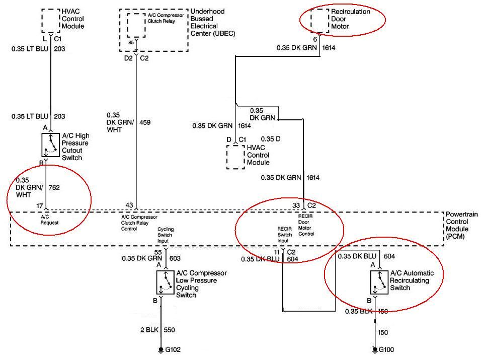
One Vehicle could have AC request via Class II and another could be hard wired. You can have a recirc door option. You can have a 2 wire high pressure cut off switch or a 3 wire high pressure transducer on the AC.
I will post some schematics
You could put a 8.1L in a Vette with Cable Drive and you could use the Vette calibration to start with.
A Vette calibration has 4X4 and PTO options in it from the factory.
One Vehicle could have AC request via Class II and another could be hard wired. You can have a recirc door option. You can have a 2 wire high pressure cut off switch or a 3 wire high pressure transducer on the AC.
I will post some schematics

 04-20-2010, 08:15 AM
#10

I`m thinking theres a few people watching this one. I`m in the same boat, with a 2003 suburban swap engine. Theres a request for the feature on the HPTuners forum, but no love so far. http://www.hptuners.com/forum/showthread.php?t=28793 Bump it if you have HPTuners, maybe they will look into it if theres enough of us.
 04-20-2010, 08:49 PM
#13
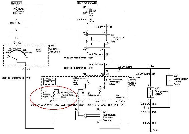
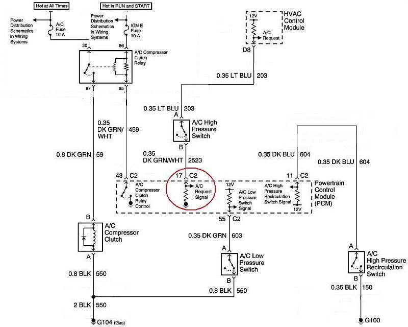
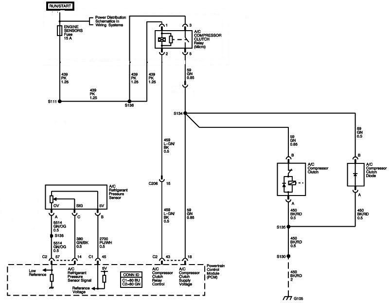
This is a 2004 Silverado -- Class II
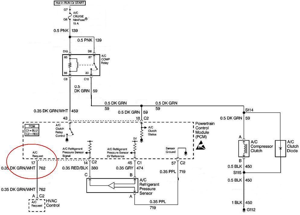
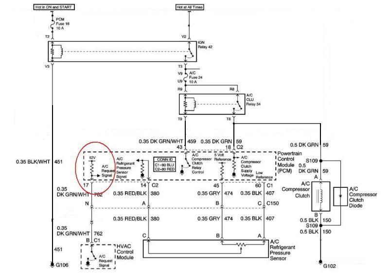
This is a 2004 Vette -- Class II
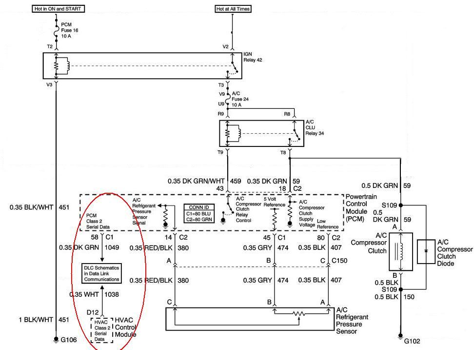
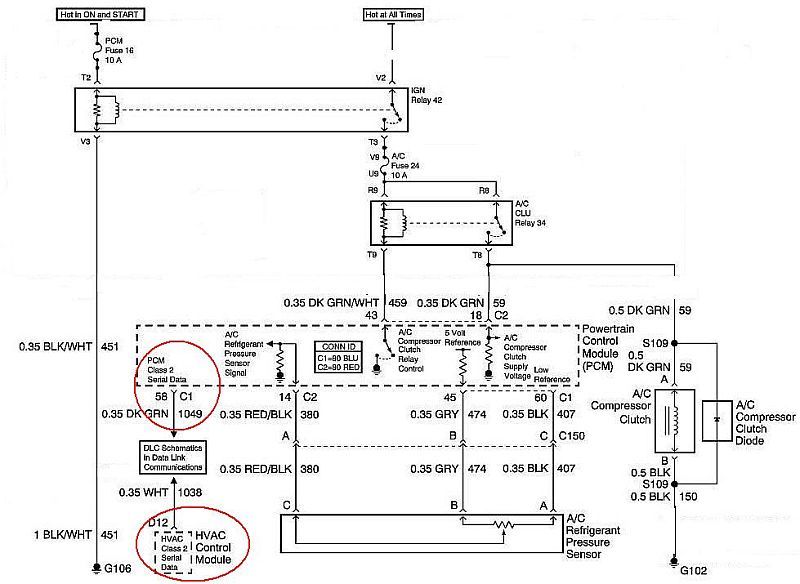
This is a 2004 GTO -- Class II
2004
GTO PCM, Cable Throttle DOES WORK:
Serv. No. 12586243
Hwd. No. 12583659

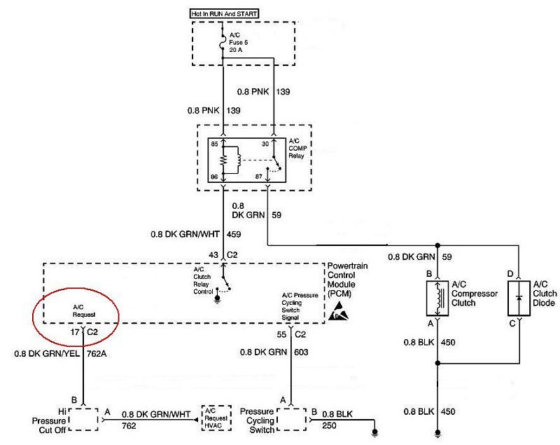
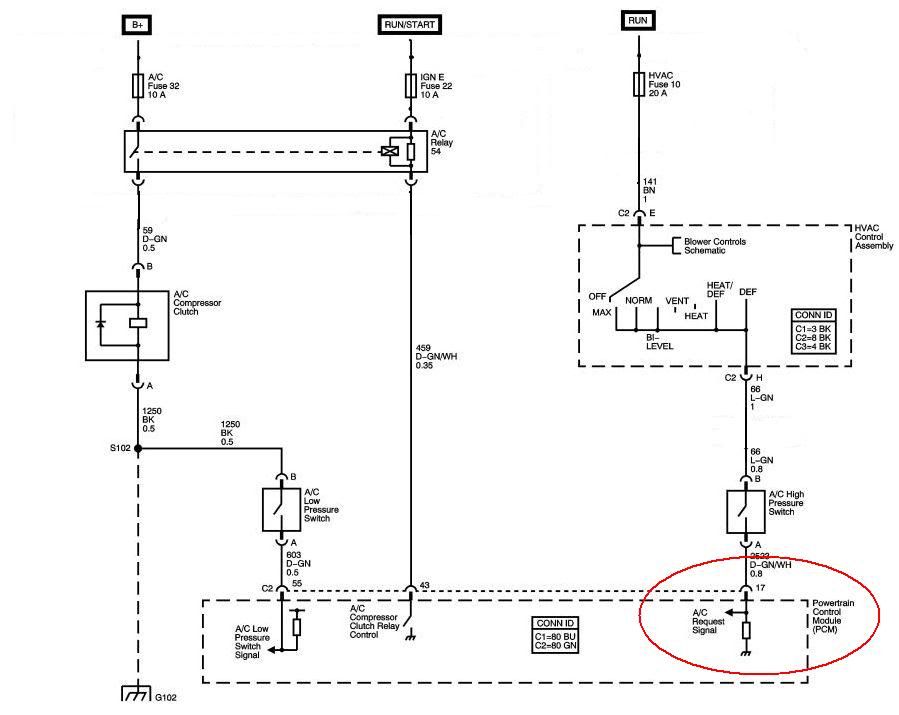
This is a 2004 Express Van -- Hard wired to pin #17
I think this is Serv. No. 12586243
This is a 2004 Vette -- Class II
This is a 2004 GTO -- Class II
2004
GTO PCM, Cable Throttle DOES WORK:
Serv. No. 12586243
Hwd. No. 12583659
This is a 2004 Express Van -- Hard wired to pin #17
I think this is Serv. No. 12586243
 05-28-2010, 10:08 PM
#16
Teching In

Join Date: Jul 2009
Location: iowa
Posts: 13
Likes: 0
Received 0 Likes
on
0 Posts
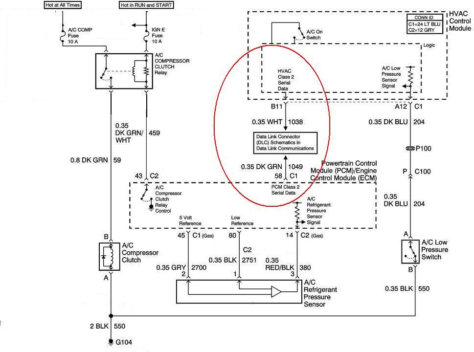
All the a/c requestr signal is, is a 12 volt power signal to that pin in the pcm. If you wanted you could put 12 volts to it with a toggle switch. Once the pcm has 12 volts on that pin it closes the conact for the ac clutch relay. sweet, simple, to the point, it doesn't matter where the 12 volt signal comes from as long as it has the signal. As was mentioned previously one system gets the request from the bcm... if you arent using a bcm no problem, cause the pcm does't care where the signal comes from just that it has the signal.
05-29-2010, 07:15 PM
#17
All the a/c requestr signal is, is a 12 volt power signal to that pin in the pcm. If you wanted you could put 12 volts to it with a toggle switch. Once the pcm has 12 volts on that pin it closes the conact for the ac clutch relay. sweet, simple, to the point, it doesn't matter where the 12 volt signal comes from as long as it has the signal. As was mentioned previously one system gets the request from the bcm... if you arent using a bcm no problem, cause the pcm does't care where the signal comes from just that it has the signal.

