Conversions & Swaps LSX Engines in Non-LSX Vehicles
Sponsored by:
Sponsored by:

New mechanical speedometer drive solution

Thread Tools
 
Search this Thread
 
Old 02-18-2012, 08:07 AM
  #81  
TECH Regular
Thread Starter
iTrader: (11)
 
SUPERBOOST's Avatar
 
Join Date: May 2007
Location: Georgia
Posts: 465
Likes: 0
Received 1 Like on 1 Post
Default

This is a much needed fix,we appreciate you guys working this out.
Old 02-24-2012, 01:18 PM
  #82  
Teching In
iTrader: (1)
 
Friggy's Avatar
 
Join Date: Jan 2012
Location: Maine
Posts: 44
Likes: 0
Received 0 Likes on 0 Posts
Default

I know it's only been a week, but any update on this. My swap motor just showed up and I am getting antsy.
Old 02-24-2012, 05:00 PM
  #83  
TECH Regular
iTrader: (5)
 
zipster's Avatar
 
Join Date: Feb 2010
Location: Celina, Texas
Posts: 456
Likes: 0
Received 0 Likes on 0 Posts

Default

Its up date time, everything looks good. Testing the motor for long term high speed. The original coupler failed at 8700 miles. The reason it failed was the mount was off center, causing strain on the coupler. And the motor was 90 degrees. Now the coupler is perfect and the motor is only 58 degrees. The electronics are coming along, we should be testing the prototype in a couple of days.

I just want to thank the whole board for the support. We are working hard on this to make it happen. I need it to happen, I am driving my wife nuts!

Thanks again everyone!
Old 02-24-2012, 06:18 PM
  #84  
TECH Regular
iTrader: (1)
 
2165 Turbo Rail's Avatar
 
Join Date: Sep 2010
Location: Carrollton, TX
Posts: 403
Likes: 0
Received 1 Like on 1 Post
Default

I'm happy to hear this. I'm going to need one soon ( few months ). Hope you're ready lol
Old 02-24-2012, 06:47 PM
  #85  
On The Tree
 
jbsjunk's Avatar
 
Join Date: Dec 2008
Location: West Mich
Posts: 165
Likes: 0
Received 0 Likes on 0 Posts
Default

It would be nice if this could be adjusted on the fly. I'm not in any hurry yet, still need to finish things and work the bugs out of it.
Old 02-24-2012, 07:36 PM
  #86  
On The Tree
 
Stovebolter's Avatar
 
Join Date: Dec 2007
Location: Harrison Arkansas
Posts: 108
Likes: 0
Received 0 Likes on 0 Posts
Default

Same here, build still in progress, but you can count me in!!!

David
Old 02-24-2012, 07:46 PM
  #87  
TECH Regular
iTrader: (5)
 
zipster's Avatar
 
Join Date: Feb 2010
Location: Celina, Texas
Posts: 456
Likes: 0
Received 0 Likes on 0 Posts

Default

Stovebolter,

Could you send me a picture of the back of your speedometer? I want to see the part where the cable connects to.
Old 02-24-2012, 08:25 PM
  #88  
On The Tree
 
Stovebolter's Avatar
 
Join Date: Dec 2007
Location: Harrison Arkansas
Posts: 108
Likes: 0
Received 0 Likes on 0 Posts
Default

Originally Posted by zipster
Stovebolter,

Could you send me a picture of the back of your speedometer? I want to see the part where the cable connects to.
I'll have to take a pic later cause I'm not sure what I'm going to use yet. It'll probably be some old school Stewart Warner's that I have but may stay with the stock gauges. What ever I use will have the standard style Chevrolet cable like off a TH350.

David
Old 02-24-2012, 09:50 PM
  #89  
On The Tree
iTrader: (2)
 
thenova70ss's Avatar
 
Join Date: Nov 2010
Location: Arkansas
Posts: 184
Likes: 0
Received 1 Like on 1 Post
Default

OK Guys just got off the Phone with Tim AKA zipster and i will have a Prototype to take on the 2012 Hot Rod Power Tour for all you guys to look at. I will all so have one in my car for testing to give Tim and them real world feed back on a Long 1300 mile trip. I am so happy to be testing this for Tim and i will do my best on the Hot Rod Power Tour to give you guys all the info i can on this GREAT new item to the LS world.

Congrats Tim for the GREAT work you are doing to help all use LS guys out.
Old 02-25-2012, 03:24 PM
  #90  
Registered User
 
cadence's Avatar
 
Join Date: Feb 2012
Posts: 1
Likes: 0
Received 0 Likes on 0 Posts
Default

any chance that this will also work with an inductive pickup on the u-joint bolt? i have a transmission that doesn't have a speed sensor or cable output.
Old 02-25-2012, 03:29 PM
  #91  
On The Tree
 
jbsjunk's Avatar
 
Join Date: Dec 2008
Location: West Mich
Posts: 165
Likes: 0
Received 0 Likes on 0 Posts
Default

If THIS kit can be made to work, you will have a speed sensor signal.
Old 02-25-2012, 04:25 PM
  #92  
TECH Regular
iTrader: (5)
 
zipster's Avatar
 
Join Date: Feb 2010
Location: Celina, Texas
Posts: 456
Likes: 0
Received 0 Likes on 0 Posts

Default

Originally Posted by cadence
any chance that this will also work with an inductive pickup on the u-joint bolt? i have a transmission that doesn't have a speed sensor or cable output.
Originally Posted by jbsjunk
If THIS kit can be made to work, you will have a speed sensor signal.
jbsjunk has shown a way to do it.

cadence, I need more info on your car. What computer, differential, body of vehicle(brakes)
Old 02-26-2012, 03:13 PM
  #93  
TECH Regular
iTrader: (5)
 
zipster's Avatar
 
Join Date: Feb 2010
Location: Celina, Texas
Posts: 456
Likes: 0
Received 0 Likes on 0 Posts

Default

Small milestone, The test Mustang speedo has been running for 4 days at 140 mph. The motor temp is at 56 degrees, within 1 degree of ambient temp in the garage. The motor is just whizzing along. So far there are 13,593 miles on the test unit. No failures, no problems. I rolled back this speedo to 0 miles to start testing to keep accurate track of miles.

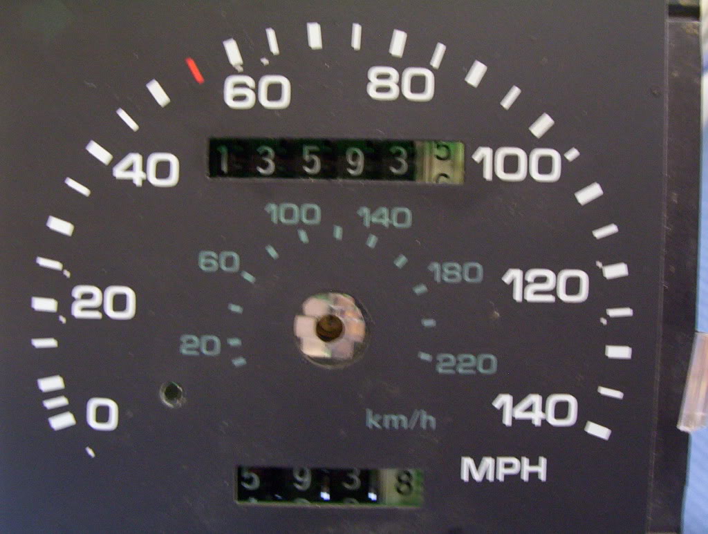
This speedo is missing the needle. I had to mark the small drum on the back to see how fast its going.

Name:  002.jpg
Views: 1794
Size:  95.2 KB

Last edited by zipster; 02-26-2012 at 03:20 PM.
Old 02-26-2012, 04:37 PM
  #94  
TECH Regular
Thread Starter
iTrader: (11)
 
SUPERBOOST's Avatar
 
Join Date: May 2007
Location: Georgia
Posts: 465
Likes: 0
Received 1 Like on 1 Post
Default

Looks like youve about got it whipped.Thats great!
Old 02-26-2012, 04:46 PM
  #95  
Launching!
 
bitterman's Avatar
 
Join Date: Jun 2011
Location: Canada
Posts: 253
Likes: 0
Received 0 Likes on 0 Posts
Default

Sounds awesome!

If you need any help with the code let me know. I'm sure I can help.

Bruce
Old 02-26-2012, 08:11 PM
  #96  
-Q-
TECH Fanatic
iTrader: (10)
 
-Q-'s Avatar
 
Join Date: Mar 2003
Location: St Simons Isl, GA
Posts: 1,106
Likes: 0
Received 2 Likes on 2 Posts

Default

This is outstanding. If you were to need a speedo from a C3 Corvette for any reason, please let me know...mine's out of the car, and won't be needed for a bit.
Old 02-26-2012, 10:06 PM
  #97  
8 Second Club
 
LILHEMI's Avatar
 
Join Date: Apr 2006
Location: in my neighborhood
Posts: 1,009
Received 30 Likes on 15 Posts

Default

In for updates.
Old 02-28-2012, 11:15 AM
  #98  
11 Second Club
iTrader: (8)
 
Agent_Orange_Shuvel's Avatar
 
Join Date: Jan 2010
Location: Southern Idaho
Posts: 502
Likes: 0
Received 0 Likes on 0 Posts
Default

Awesome work, I will definitely be checking back on this when my build nears completion.
Old 02-28-2012, 12:12 PM
  #99  
Teching In
 
invader59's Avatar
 
Join Date: Nov 2011
Location: Chambana, IL
Posts: 29
Likes: 0
Received 0 Likes on 0 Posts
Default

Just a status update on the logical/electronic portion of this project - the base code for the embedded program compiles and loads fine. I am still tweaking the motor power supply design for the final (need to make sure it can take supply tension loaded up to 35v, isolate errant currents and filter high frequency noise, jitter, and compensate undervolt conditions down to 9v), but my base PSU and amplifier designs are currently running on a breadboard on my bench and driving the motor well. Tim is taking care of the mechanical aspects of the design like a boss, so we're looking good. I still need to write the calibration and test signal generator modules. Should get to that by tomorrow night.
Old 02-28-2012, 12:53 PM
  #100  
-Q-
TECH Fanatic
iTrader: (10)
 
-Q-'s Avatar
 
Join Date: Mar 2003
Location: St Simons Isl, GA
Posts: 1,106
Likes: 0
Received 2 Likes on 2 Posts

Default

Originally Posted by invader59
Just a status update on the logical/electronic portion of this project - the base code for the embedded program compiles and loads fine. I am still tweaking the motor power supply design for the final (need to make sure it can take supply tension loaded up to 35v, isolate errant currents and filter high frequency noise, jitter, and compensate undervolt conditions down to 9v), but my base PSU and amplifier designs are currently running on a breadboard on my bench and driving the motor well. Tim is taking care of the mechanical aspects of the design like a boss, so we're looking good. I still need to write the calibration and test signal generator modules. Should get to that by tomorrow night.
Say what now?


Quick Reply: New mechanical speedometer drive solution


All times are GMT -5. The time now is 09:32 PM.