
71 Pontiac Lemans


 02-02-2013, 05:53 PM
#64

I will be doing the A/C on my car in a few months. It will be cold air only as I am retaining the factory heater and defroster. I am interested in the EZ-Clip fittings. Maybe a few pictures when you get to that part of the installation. I also found the pliers on Ebay for around $7.00.
02-02-2013, 09:28 PM
#65
Staging Lane
Thread Starter

Thanks for all the comments and feedback.
cbrodine: I have been following your build, it looks like we have been dealing with similar situations, a lot of rust on Ohio A-body convertibles! Maybe we will run into each other at a car event this summer.
oldgoat69: I still hope to get the car presentable by this summer, I am working on it as much as I can. Next is gas tank and drive shaft, and I am actually thinking about paint colors (blues).
1989GTA: I will document the AC lines in a future post; I spent hours figuring out how to connect to the GTO's AC components, but I think (or hope!) I have a good solution.
02-04-2013, 08:32 AM
#66
Staging Lane
Thread Starter
2004 GTO Interior � Steering
This post will show installing the steering column from the GTO donor into the Lemans. I wanted to get the steering column installation figured out before the dash went in because the area is easier to get access to.
I had previously mocked up where I wanted to dash to go, so I knew about how far rearward the column needed to be to mate up with the relocated dash supporting structure.
I have seen different ways to do this on other builds but either I didn�t care for what was done in the past or it wouldn�t work in my situation. I didn�t want to modify steering parts with welding and cutting on the column and linkage parts. I wanted a bolt together solution that was safe and secure.
The main issue of this installation is supporting the column at the Lemans firewall. I first thought about using the column mount on the GTO firewall that was installed to support the dash, but it didn�t seem secure enough, and I still had the issue with sealing the opening through the Lemans firewall where the steering shaft passes through. So I made an adapter that mounts the GTO donor column to the Lemans firewall. It�s basically two plates connected by a sheet metal �tunnel� that the steering shaft passes through. One plate attaches to the Lemans firewall, the other bolts to the bottom of the GTO column. The description and pictures below describe the process.
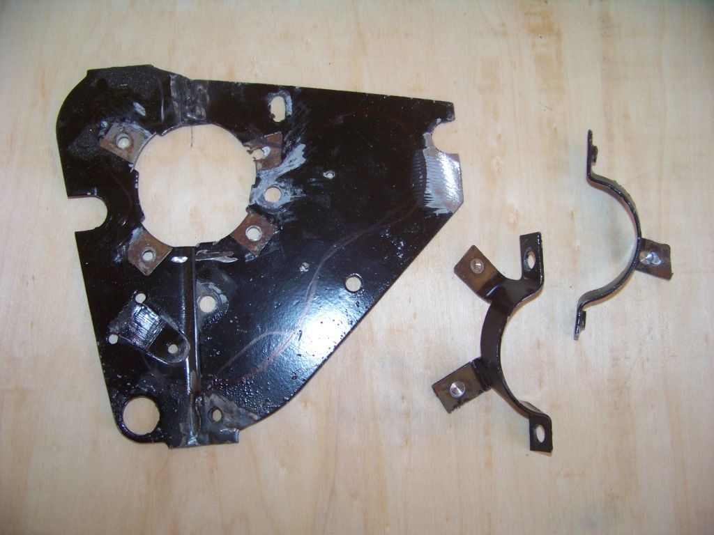
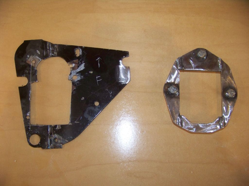
The picture below shows the steering column closeout plate for the firewall of the Lemans. I removed the column clamp brackets as shown.
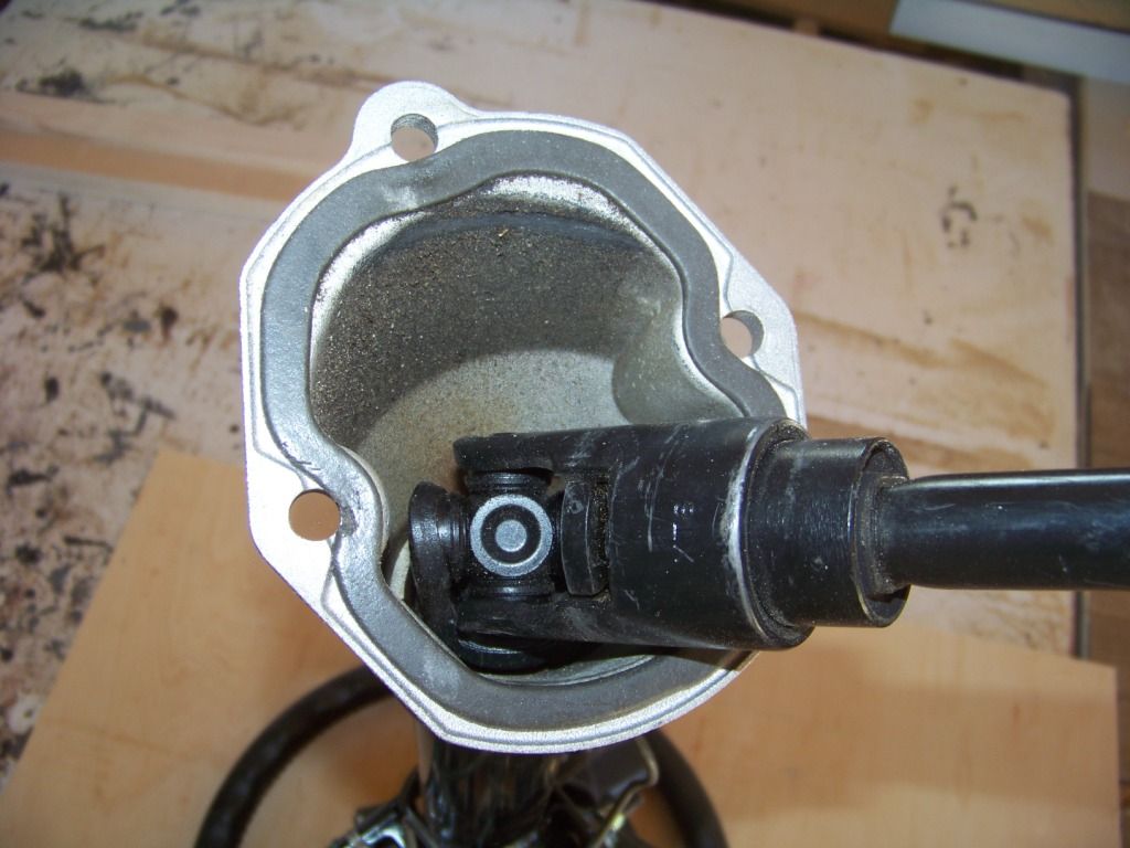
The picture below shows the bottom on the GTO column where it attaches to the GTO firewall:
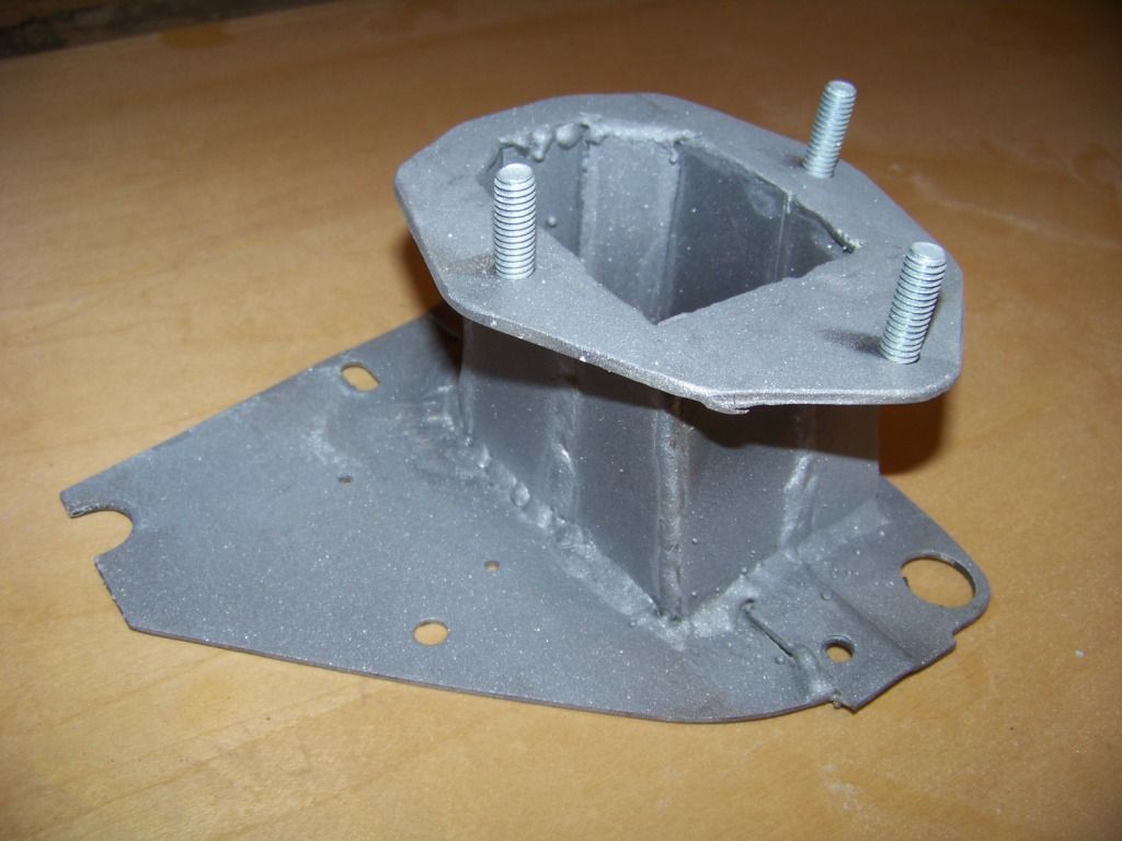
The next couple of pictures show the plate I made to support the bottom of the GTO column:
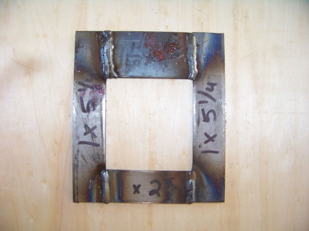
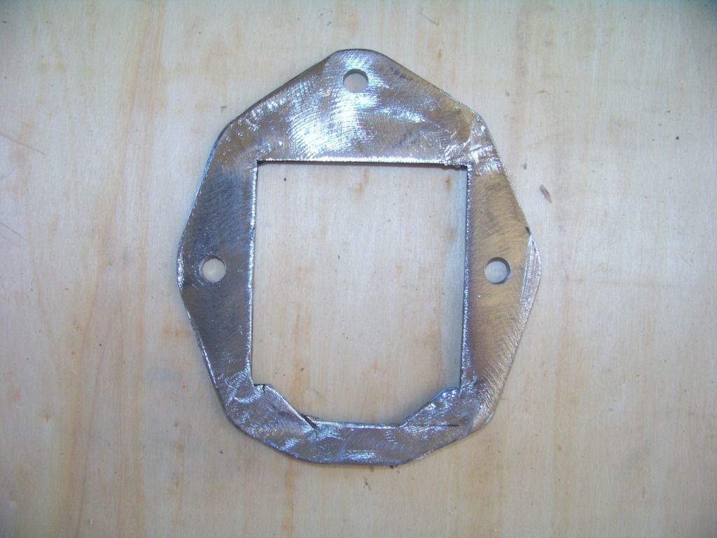
The pictures below show the construction of the whole column adapter assembly.
The next two pictures how the steering column adapter assembly installed with the GTO steering column bolted to it.
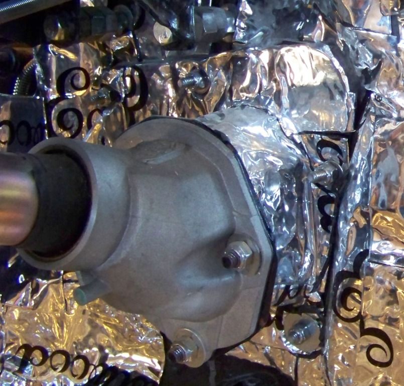
Now that the column is mounted, I could connect the GTO's steering column shaft to the steering gearbox. The bottom of the GTO donor column connected to the GTO steering rack with a �� DD connection. The shaft on the Jeep Cherokee steering gearbox is �� diameter, 30 spline with a flat. I bought the following parts to connect the two together:
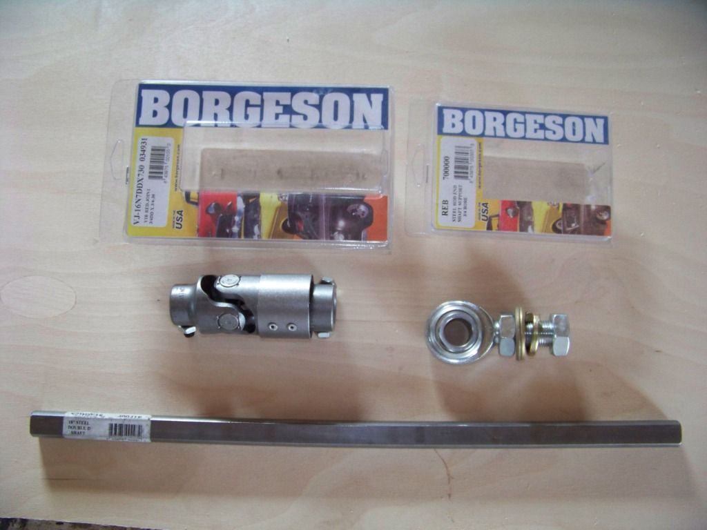
Parts are all from Borgensen; BRG-034931 u-joint, BRG-409418 Steering Shaft, and BRG-700000 3/4" support bearing.
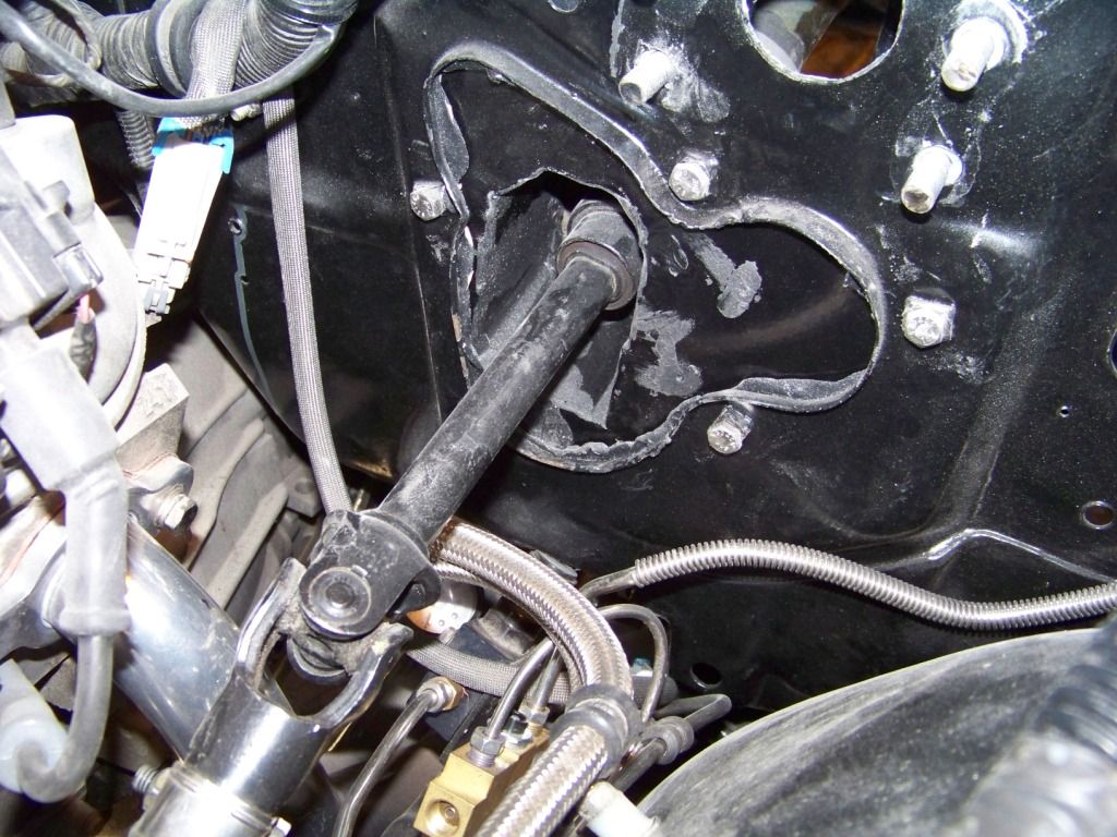
The coupler installed onto the steering gearbox and allowed for a connection to the �� DD shaft which was trimmed to length. This then connected to the �� DD opening at the bottom of the GTO column (in black in the second picture below). Not shown here but there is another universal joint higher up in the GTO column. Since this steering connection has a total of three universal joints, an intermediate shaft support is required as shown below the middle connection. This shaft support is then supported by bracket I fabricated and installed on the rear upper control arm bolt. The bracket is shown below.
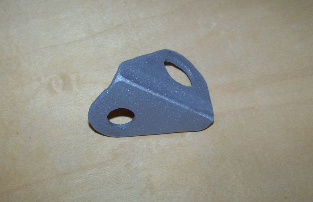
All the above parts installed as shown below.
Please feel free to ask any questions if any of this is unclear.
This post will show installing the steering column from the GTO donor into the Lemans. I wanted to get the steering column installation figured out before the dash went in because the area is easier to get access to.
I had previously mocked up where I wanted to dash to go, so I knew about how far rearward the column needed to be to mate up with the relocated dash supporting structure.
I have seen different ways to do this on other builds but either I didn�t care for what was done in the past or it wouldn�t work in my situation. I didn�t want to modify steering parts with welding and cutting on the column and linkage parts. I wanted a bolt together solution that was safe and secure.
The main issue of this installation is supporting the column at the Lemans firewall. I first thought about using the column mount on the GTO firewall that was installed to support the dash, but it didn�t seem secure enough, and I still had the issue with sealing the opening through the Lemans firewall where the steering shaft passes through. So I made an adapter that mounts the GTO donor column to the Lemans firewall. It�s basically two plates connected by a sheet metal �tunnel� that the steering shaft passes through. One plate attaches to the Lemans firewall, the other bolts to the bottom of the GTO column. The description and pictures below describe the process.
The picture below shows the steering column closeout plate for the firewall of the Lemans. I removed the column clamp brackets as shown.
The picture below shows the bottom on the GTO column where it attaches to the GTO firewall:
The next couple of pictures show the plate I made to support the bottom of the GTO column:
The pictures below show the construction of the whole column adapter assembly.
The next two pictures how the steering column adapter assembly installed with the GTO steering column bolted to it.
Now that the column is mounted, I could connect the GTO's steering column shaft to the steering gearbox. The bottom of the GTO donor column connected to the GTO steering rack with a �� DD connection. The shaft on the Jeep Cherokee steering gearbox is �� diameter, 30 spline with a flat. I bought the following parts to connect the two together:
Parts are all from Borgensen; BRG-034931 u-joint, BRG-409418 Steering Shaft, and BRG-700000 3/4" support bearing.
The coupler installed onto the steering gearbox and allowed for a connection to the �� DD shaft which was trimmed to length. This then connected to the �� DD opening at the bottom of the GTO column (in black in the second picture below). Not shown here but there is another universal joint higher up in the GTO column. Since this steering connection has a total of three universal joints, an intermediate shaft support is required as shown below the middle connection. This shaft support is then supported by bracket I fabricated and installed on the rear upper control arm bolt. The bracket is shown below.
All the above parts installed as shown below.
Please feel free to ask any questions if any of this is unclear.
02-05-2013, 06:17 AM
#67
TECH Fanatic
What are your plans for the gas tank? If the GTO tank is not an option take a look at a 94-96 B body tank. This is almost a bolt in. You might be able to use the GTO fuel pump in the B tank
02-05-2013, 09:00 AM
#68
Staging Lane
Thread Starter
oldgoat69:
I have looked through all the options, the Spectra EFI tank, Ricks Tank, the B-body tank, etc. Over the last couple of weeks I have been fussing around with the GTO tank and I think I have a good plan to use that. This keeps in with my theme of using as many of the GTO's components as possible and keeping it plug and play. Just bought some materials yesterday to make that happen and hope to have a post documenting it in the near future.
The GTO donor tank actually sits pretty well in the forward part of the trunk directly below the panel between the rear window and trunk opening. I cannot put it over the rear axle as it is on the new GTO because as you know that's where the top goes down into. This does impact trunk space somewhat, but I am also thinking of mounting the donor GTO's spare tire and evap canister under the trunk where the original a-body tank used to be so I think this should get me a better usable trunk space anyway instead of having the spare in the middle of the trunk floor as it normally is in an a-body.
Thanks,
Phil
Last edited by fsdproject; 02-07-2013 at 06:00 PM.
02-06-2013, 06:14 AM
#69
TECH Fanatic
Sounds like an interesting engineering project. This is surely a way to get people scratching their heads at car shows. Except for the filler nozzle I can't see any reason not to do it this way. Are you planning to have an exterior gas door like the GTO would have?
02-08-2013, 06:24 AM
#71
Staging Lane
Thread Starter
oldgoat69: The other day I finished fabricating the parts for the tank install, they just need to be painted. And I have the feed and vapor lines figured out. So I hope to have the tank finally installed next week, I will post when I do. I have been thinking about two options for the filler nozzle, a exterior gas door like the GTO or one of those chrome caps on top of the fender like on a Challenger. The GTO door has a good curve to it and the side of the Lemans' fender is mostly flat so I don't think it's possible to use it. Initially I will just fill it from inside the trunk.
Kainedog: Thanks! I have been following your build with interest, looks like you are having fun. Your Science/Religion statement in your signature gave me a chuckle . . .
Phil
Kainedog: Thanks! I have been following your build with interest, looks like you are having fun. Your Science/Religion statement in your signature gave me a chuckle . . .
Phil
02-16-2013, 01:10 PM
#72
Staging Lane
Thread Starter
Gas Tank, Gas Line, Evap System
As mentioned in a previous post I have figured out a way to use the gas tank from the 2004 GTO donor in my Lemans convertible.
The gas tank in the GTO is installed over the rear axle between the rear seat and the trunk. It wouldn't fit in this area in the Lemans since the convertible top has to fold into that area. I placed the gas tank on the forward part of the trunk floor, it ends up fitting pretty well under the body panel between the top and the trunk opening. My design somewhat resembles how the tank was installed in the GTO.
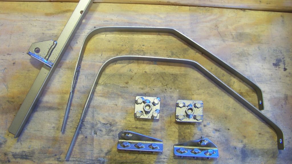
The first picture shows the hardware I fabricated to hold the tank in the car.
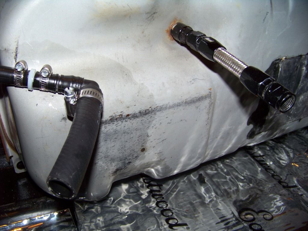
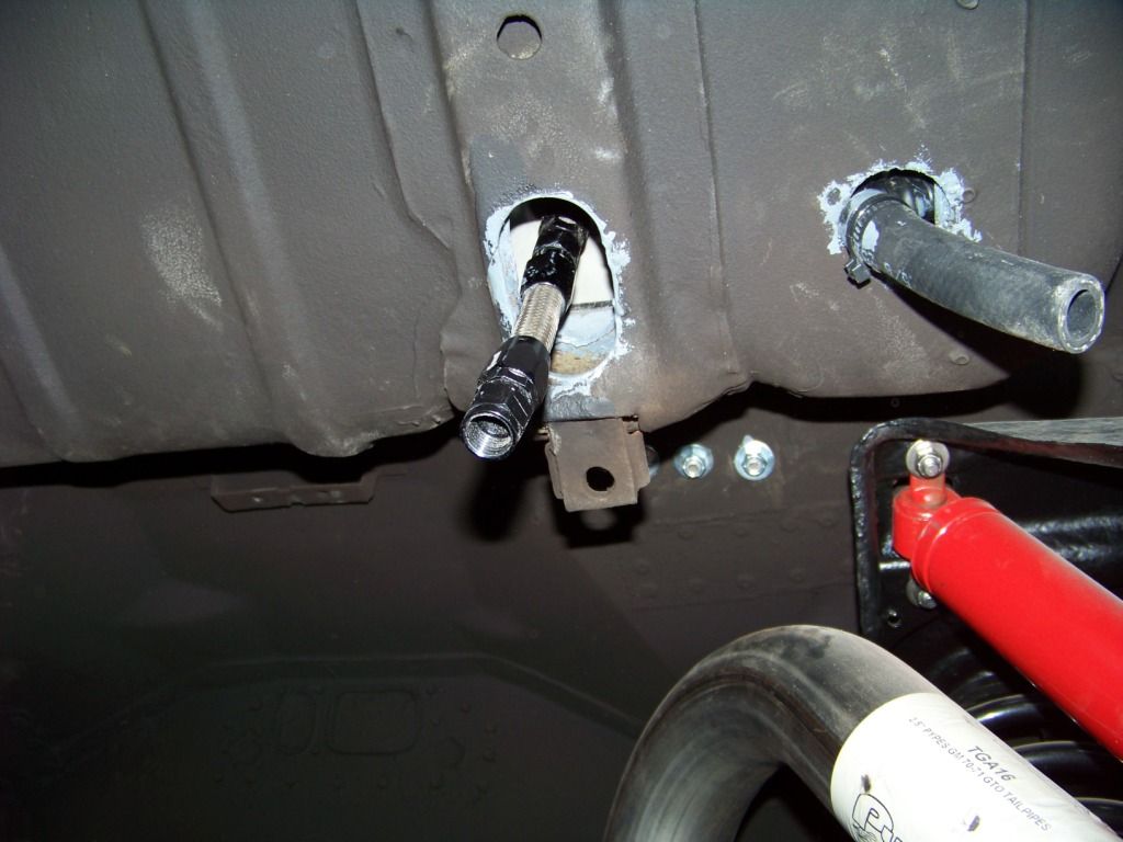
The GTO's fuel and vapor connections are on the bottom of the tank, I drilled large holes in the trunk floor to accommodate those and installed short sections of hose to feed through the floor holes, the pictures below show this. The first picture shows the tank with the black plastic shroud removed. These connections are inaccessible when the tank is installed so I had to provide secondary connections under the floor, similar to what is done with electrical pigtails. The fuel feed connection on the bottom of the tank is the same type and size as the one on the fuel rail. I used a Russell Fuel Rail to -6AN adapter, part number RUS-644123 for that and then made a small -6AN hose as shown. The vapor hose is 5/8" ID fuel rated hose I ordered from McMaster. I installed sound deadener material on the trunk floor before the tank went in. The second picture is taken from underneath and shows these hose connections.
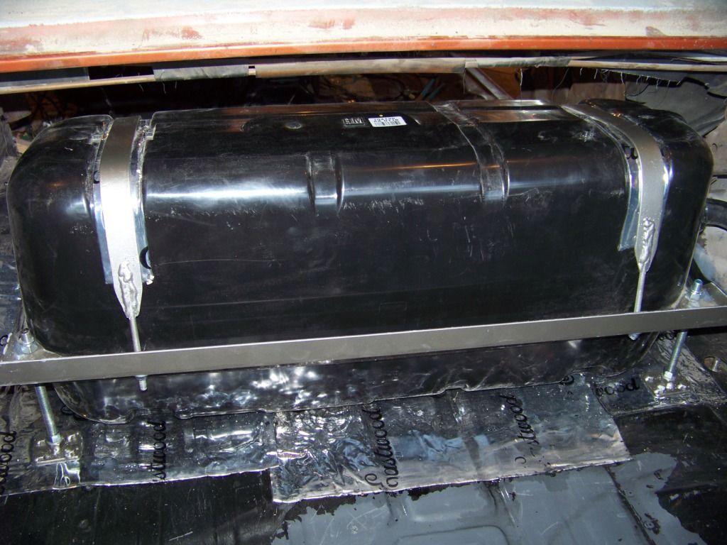
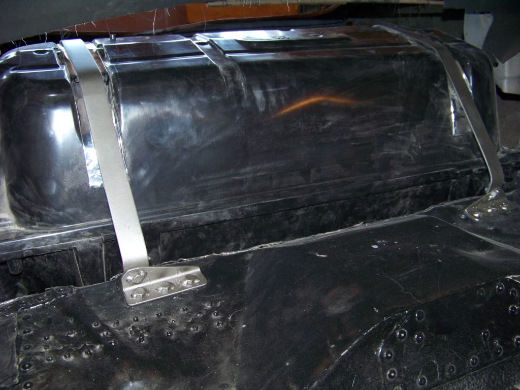
This next picture shows the installation of the tank in the forward part of the trunk. I put sound deadener material on top of the tank where the straps go to protect the plastic shroud.
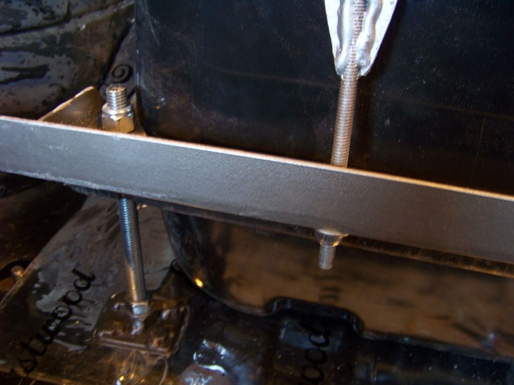
A close up of the trunk side hardware is shown below. The 1/2" threaded rods go through pre-existing holes in the aft corners on the tank, then the bottom of the threaded rods go into the plates I made on the bottom of the floor. These plates have a 1/2" nut tack welded to the middle of the plate and four 5/16" x 1" bolts tack welded to the corners. This way I could tighten the nuts underneath without having to hold the bolts above the floor. The straps are just 1/8" x 1 1/4" steel straps with 5/16 threaded rod welded into slots on one end. The rods then go through holes in the horizontal angle. The horizontal angle is attached to the aft corners of the tank with the threaded rod. The angle will also support the forward carpeted wall of the tank when I get to that point.
The picture below shows the installation on the forward part of the tank, this is looking from the rear seat area. The tank straps are bolted to brackets that are installed into the floor. The brackets have four 5/16" x 1" bolts tacked onto them, three go through the floor and are bolted underneath, the remaining one holds the end of the strap.
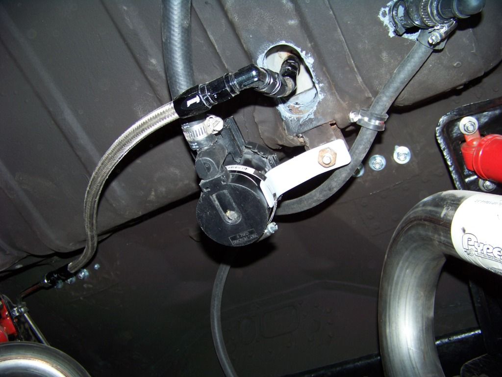
The next picture shows the installation of the EVAP cannister vent solenoid, this is a view looking up at the bottom of the trunk floor. I made the simple bracket shown below that is bolted to the former forward gas tank strap support in the Lemans, a hose clamp holds the solenoid to the bracket. This picture also shows the AN hose I made to connect the pigtail hose on the tank to the fuel rail that runs along the frame rail.
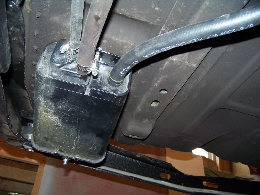
The following picture shows the installation of the EVAP canister which I bolted to the bottom of the trunk floor just inside the frame rail forward of the last frame crossmember.
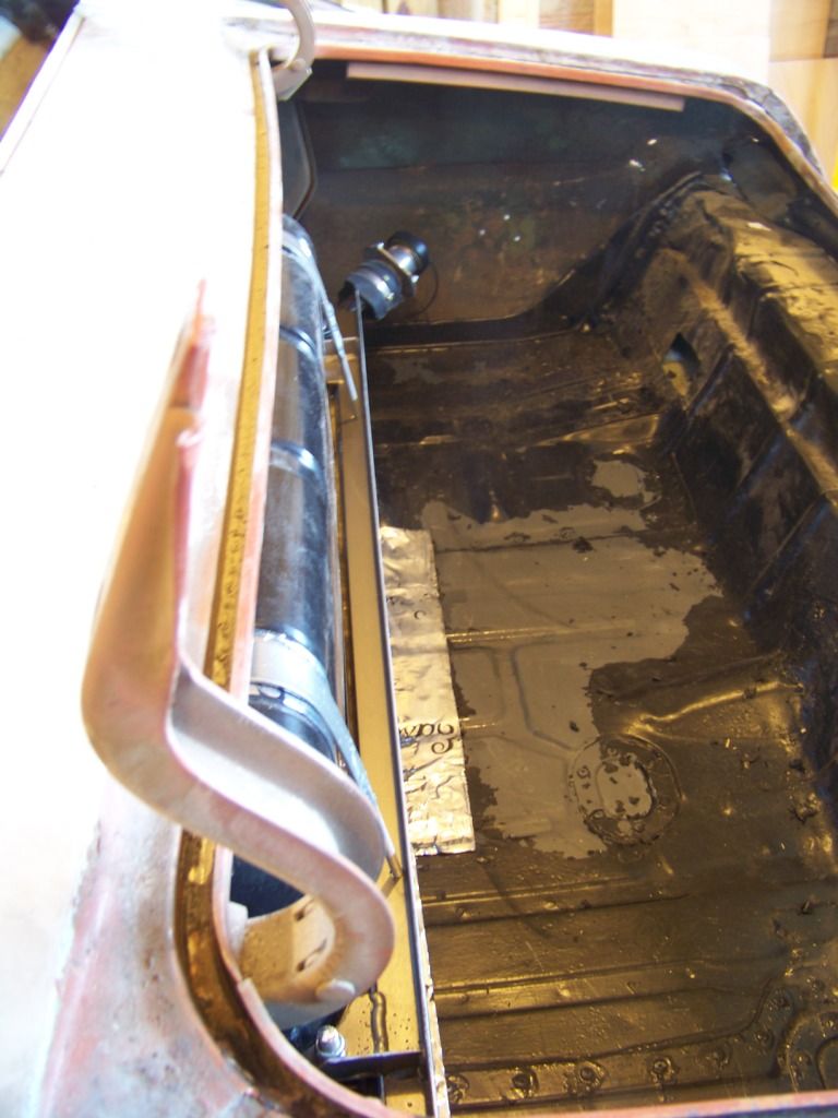
The view below is from the side of the car looking into the trunk, it shows how much the gas tank protrudes into the trunk area; which isn't too bad. I did loose some trunk area, but as I said before my plan is to install the GTO donor spare tire under the trunk floor so I think I still have a nice usable trunk space.
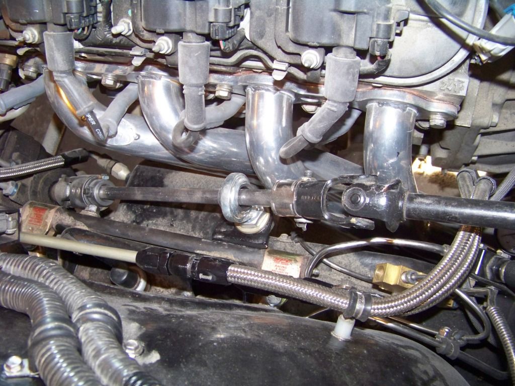
This final picture shows the fuel line installation on the engine. I ran the standard a-body fuel line in stainless along the frame rail and installed tube compression to -6AN fittings at each end. At the engine side I ran some -6AN hoses as shown and also added a permanent fuel pressure gauge. In this view you can also see the vapor hose connection just underneath the coil electrical connector. This is just 3/8 fuel injection hose that runs along the passenger side frame rail to the evap canister.
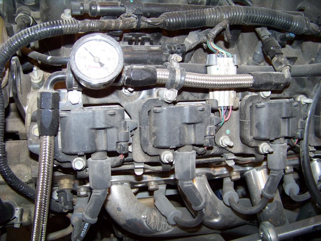
I am very pleased with the way this has worked out. I used another major component from the GTO donor, didn't have to buy another gas tank, fuel pump and sender and figure out how to hook those up. Since these are the OEM components everything works as it was designed to including the fuel gauge.
As mentioned in a previous post I have figured out a way to use the gas tank from the 2004 GTO donor in my Lemans convertible.
The gas tank in the GTO is installed over the rear axle between the rear seat and the trunk. It wouldn't fit in this area in the Lemans since the convertible top has to fold into that area. I placed the gas tank on the forward part of the trunk floor, it ends up fitting pretty well under the body panel between the top and the trunk opening. My design somewhat resembles how the tank was installed in the GTO.
The first picture shows the hardware I fabricated to hold the tank in the car.
The GTO's fuel and vapor connections are on the bottom of the tank, I drilled large holes in the trunk floor to accommodate those and installed short sections of hose to feed through the floor holes, the pictures below show this. The first picture shows the tank with the black plastic shroud removed. These connections are inaccessible when the tank is installed so I had to provide secondary connections under the floor, similar to what is done with electrical pigtails. The fuel feed connection on the bottom of the tank is the same type and size as the one on the fuel rail. I used a Russell Fuel Rail to -6AN adapter, part number RUS-644123 for that and then made a small -6AN hose as shown. The vapor hose is 5/8" ID fuel rated hose I ordered from McMaster. I installed sound deadener material on the trunk floor before the tank went in. The second picture is taken from underneath and shows these hose connections.
This next picture shows the installation of the tank in the forward part of the trunk. I put sound deadener material on top of the tank where the straps go to protect the plastic shroud.
A close up of the trunk side hardware is shown below. The 1/2" threaded rods go through pre-existing holes in the aft corners on the tank, then the bottom of the threaded rods go into the plates I made on the bottom of the floor. These plates have a 1/2" nut tack welded to the middle of the plate and four 5/16" x 1" bolts tack welded to the corners. This way I could tighten the nuts underneath without having to hold the bolts above the floor. The straps are just 1/8" x 1 1/4" steel straps with 5/16 threaded rod welded into slots on one end. The rods then go through holes in the horizontal angle. The horizontal angle is attached to the aft corners of the tank with the threaded rod. The angle will also support the forward carpeted wall of the tank when I get to that point.
The picture below shows the installation on the forward part of the tank, this is looking from the rear seat area. The tank straps are bolted to brackets that are installed into the floor. The brackets have four 5/16" x 1" bolts tacked onto them, three go through the floor and are bolted underneath, the remaining one holds the end of the strap.
The next picture shows the installation of the EVAP cannister vent solenoid, this is a view looking up at the bottom of the trunk floor. I made the simple bracket shown below that is bolted to the former forward gas tank strap support in the Lemans, a hose clamp holds the solenoid to the bracket. This picture also shows the AN hose I made to connect the pigtail hose on the tank to the fuel rail that runs along the frame rail.
The following picture shows the installation of the EVAP canister which I bolted to the bottom of the trunk floor just inside the frame rail forward of the last frame crossmember.
The view below is from the side of the car looking into the trunk, it shows how much the gas tank protrudes into the trunk area; which isn't too bad. I did loose some trunk area, but as I said before my plan is to install the GTO donor spare tire under the trunk floor so I think I still have a nice usable trunk space.
This final picture shows the fuel line installation on the engine. I ran the standard a-body fuel line in stainless along the frame rail and installed tube compression to -6AN fittings at each end. At the engine side I ran some -6AN hoses as shown and also added a permanent fuel pressure gauge. In this view you can also see the vapor hose connection just underneath the coil electrical connector. This is just 3/8 fuel injection hose that runs along the passenger side frame rail to the evap canister.
I am very pleased with the way this has worked out. I used another major component from the GTO donor, didn't have to buy another gas tank, fuel pump and sender and figure out how to hook those up. Since these are the OEM components everything works as it was designed to including the fuel gauge.
02-16-2013, 10:37 PM
#73

Nice Job, if I may just put my 2 cents in, on the steering set up I would have used a rag joint to connect your steering shaft to the steering gear box, I think you will find you will get an annoying amount of vibration through the shaft all the way to the steering wheel, which on a long drive will make your fingers tingly and put your hands to sleep.
Second 2 cents you may want to consider some type of firewall between your GTO fuel tank and your rear seat area, in a hard rear end collision your fuel tank can be compromised, splashing raw gasoline into the inside cabin of your Lemans and then we know what happens next. If you look on your donor GTO there is a metal firewall between the tank and rear seat area which is one of he hurdles the Australian Holden AKA American GTO had to overcome to be certified for sales in the USA. The Holden does not have the fuel tank in the trunk, it is underneath the trunk area outside of the vehicle.
Second 2 cents you may want to consider some type of firewall between your GTO fuel tank and your rear seat area, in a hard rear end collision your fuel tank can be compromised, splashing raw gasoline into the inside cabin of your Lemans and then we know what happens next. If you look on your donor GTO there is a metal firewall between the tank and rear seat area which is one of he hurdles the Australian Holden AKA American GTO had to overcome to be certified for sales in the USA. The Holden does not have the fuel tank in the trunk, it is underneath the trunk area outside of the vehicle.
 02-17-2013, 09:01 AM
#75
TECH Fanatic
I have to second lizeec in regard to a fire break. Something like this is required by most race sanctioning bodies for a trunk mounted fuel tank. Not a really big deal to do, just a simple bulkhead behind the top well.
02-17-2013, 05:17 PM
#76
Staging Lane
Thread Starter
classiccaprice: Thanks for the feedback, using the donor car is working out even better than I hoped it would. I would highly recommend it to anyone doing a swap to the degree that I am.
lizeec & oldgoat69:
I do appreciate your suggestions and feedback on the safety of the gas tank installation. I want this car to be as safe and reliable as possible.
I was aware of the issues and controversy surrounding the design of the gas tank on the GTO. I sometimes read the GTO forums to educate myself about the donor car and do come across comments such as yours now and then.
Shown below is a picture of the rear seat area of my donor GTO.
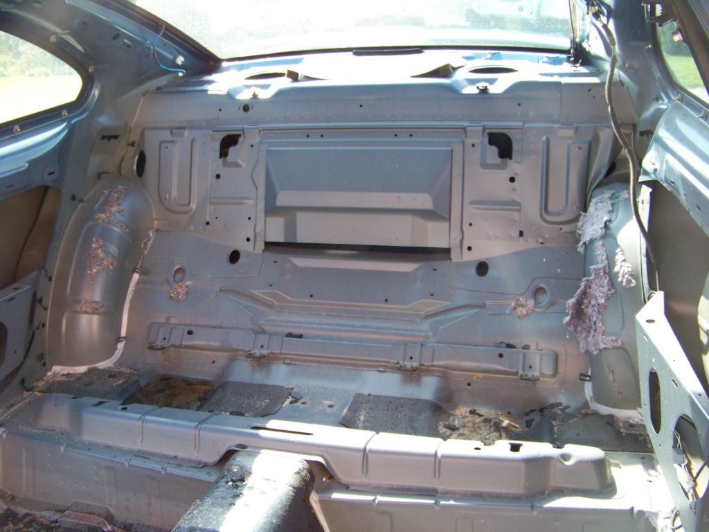
As you can see this structure has plenty of holes in it including a pretty large slot at the bottom of the trunk floor where gas could come pouring into the passenger compartment. This is what it looked like after I removed the seats, there was no plastic or sealant covering these holes. The gas tank was about an inch or two behind this with nothing else in between. Ironically there was a heavy bar like structure bolted in after the tank between the tank and trunk area, but only this single layer of sheet metal in front of the tank. So this area is definitely not sealed. I assume from this that it must not have been a concern at the time; in addition I haven't heard of any issues with this with GTOs that have been in serious wrecks but if you have definitely let me know. When I move a component over from the GTO donor I try to reproduce how it was installed, assuming that a team of engineers did the best they could to made it function well so it would be in my best interest to try and duplicate what they did as close as possible.
There is no ideal place to put a gas tank, every spot is going to have some pros and cons. As you know, the original a-body tank is just forward of the rear bumper with the filler neck extending rearward just behind the license plate. As we know now with the exploding Ford Pintos no manufacturers do that design anymore. So in some ways I feel like this installation is better than the original in that it's more towards the center of the car and therefore perhaps better protected in the event of a serious wreck.
It's unlikely I will ever autocross or race this car, it's just going to be a fun cruiser for me and maybe even my daily driver if it comes out like I hope it does. So I am not concerned about passing a sanctioning body at a racetrack.
All that being said, I am concerned about the situation and as I said I do want to make the car as safe as possible. I have thought about installing some type of sheet metal wall just forward of the tank. I don't think it would be the simple matter it appears at first, the convertible top frame does fold down near the top of the tank, and the rain gutter also is installed in this area (now that I think about that the tank may be in the way of the gutter). And there is some reinforcement structure under the panel between the top well and trunk opening that would be hard to tie into and seal. Perhaps a wall going most of the way up would be a compromise.
For the steering connection at the steering box the universal joint I bought does have a vibration damper feature on it, so hopefully that takes care of that issue.
Borgeson U-Joint
Thanks again for your feedback, I don't assume I know everything or what I am doing makes sense or is a good idea. That's why I am here to learn from others.
Phil
lizeec & oldgoat69:
I do appreciate your suggestions and feedback on the safety of the gas tank installation. I want this car to be as safe and reliable as possible.
I was aware of the issues and controversy surrounding the design of the gas tank on the GTO. I sometimes read the GTO forums to educate myself about the donor car and do come across comments such as yours now and then.
Shown below is a picture of the rear seat area of my donor GTO.
As you can see this structure has plenty of holes in it including a pretty large slot at the bottom of the trunk floor where gas could come pouring into the passenger compartment. This is what it looked like after I removed the seats, there was no plastic or sealant covering these holes. The gas tank was about an inch or two behind this with nothing else in between. Ironically there was a heavy bar like structure bolted in after the tank between the tank and trunk area, but only this single layer of sheet metal in front of the tank. So this area is definitely not sealed. I assume from this that it must not have been a concern at the time; in addition I haven't heard of any issues with this with GTOs that have been in serious wrecks but if you have definitely let me know. When I move a component over from the GTO donor I try to reproduce how it was installed, assuming that a team of engineers did the best they could to made it function well so it would be in my best interest to try and duplicate what they did as close as possible.
There is no ideal place to put a gas tank, every spot is going to have some pros and cons. As you know, the original a-body tank is just forward of the rear bumper with the filler neck extending rearward just behind the license plate. As we know now with the exploding Ford Pintos no manufacturers do that design anymore. So in some ways I feel like this installation is better than the original in that it's more towards the center of the car and therefore perhaps better protected in the event of a serious wreck.
It's unlikely I will ever autocross or race this car, it's just going to be a fun cruiser for me and maybe even my daily driver if it comes out like I hope it does. So I am not concerned about passing a sanctioning body at a racetrack.
All that being said, I am concerned about the situation and as I said I do want to make the car as safe as possible. I have thought about installing some type of sheet metal wall just forward of the tank. I don't think it would be the simple matter it appears at first, the convertible top frame does fold down near the top of the tank, and the rain gutter also is installed in this area (now that I think about that the tank may be in the way of the gutter). And there is some reinforcement structure under the panel between the top well and trunk opening that would be hard to tie into and seal. Perhaps a wall going most of the way up would be a compromise.
For the steering connection at the steering box the universal joint I bought does have a vibration damper feature on it, so hopefully that takes care of that issue.
Borgeson U-Joint
Thanks again for your feedback, I don't assume I know everything or what I am doing makes sense or is a good idea. That's why I am here to learn from others.
Phil
02-19-2013, 03:17 PM
#77
Staging Lane
Thread Starter
Air Cleaner
Back under the hood, a few more things to take care of. This post covers my air cleaner solution. I looked into different tubing and filters but I found the parts and filters get expensive in a hurry. So once again I looked at using what I took off the GTO donor.
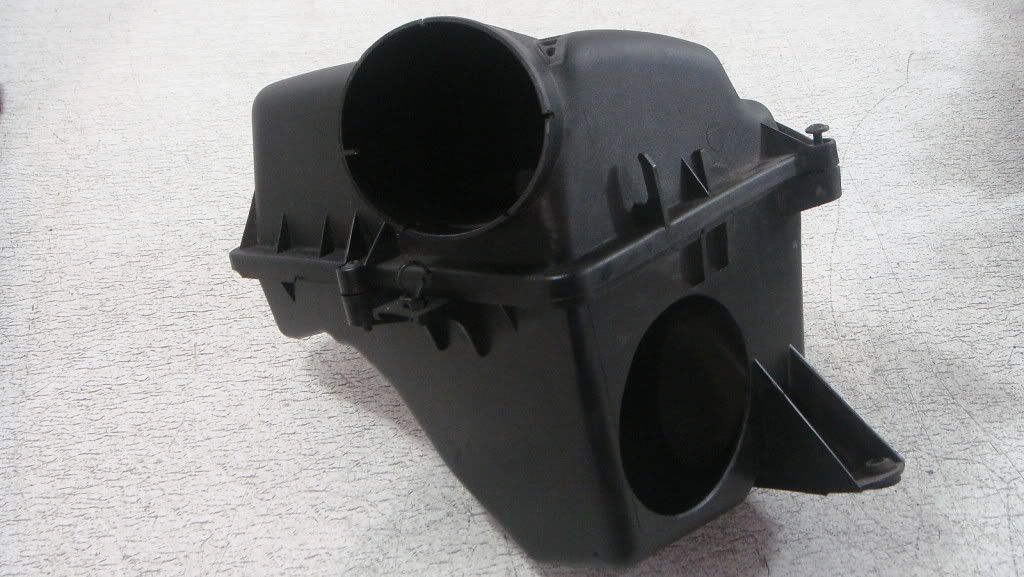
The picture below shows the air cleaner assembly from the GTO. Try as I might, I couldn�t fit this large shape anywhere under the hood of the Lemans.
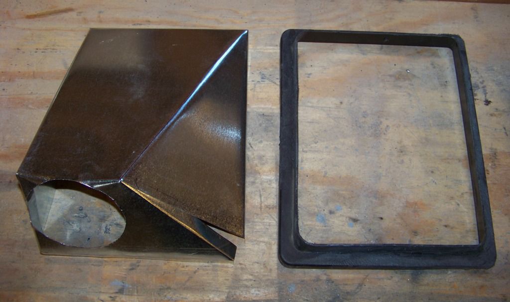
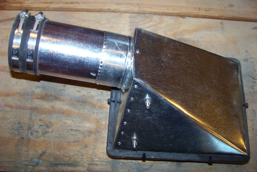
So after much fussing and cutting here is what I came up with. I chose the area under the coolant recovery tank between the core support and driver�s inner fender for the air cleaner location. I cut down the GTO air cleaner assembly to just an upper and lower frame to hold the air cleaner element and made a new sheet metal top for it as shown below. This material is just the thin sheet metal that is sold for ductwork at Lowes. This picture shows the sheet metal top before I riveted it together and the top frame of the GTO air cleaner assembly after I cut the top portion off.
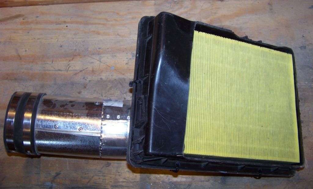
The two pictures below show the top and bottom of the completed air cleaner assembly. The sheet metal top was riveted together and to the top frame of the GTO air cleaner assembly. A 4� duct collar and 4� duct were also purchased at Lowes and attached to the sheet metal top as shown with rivets. The top and bottom frames are held together with zip ties, when I replace the filter I will just cut them off and then install new ones.
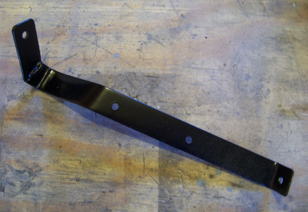
I made the bracket shown below to support the new air cleaner assembly:
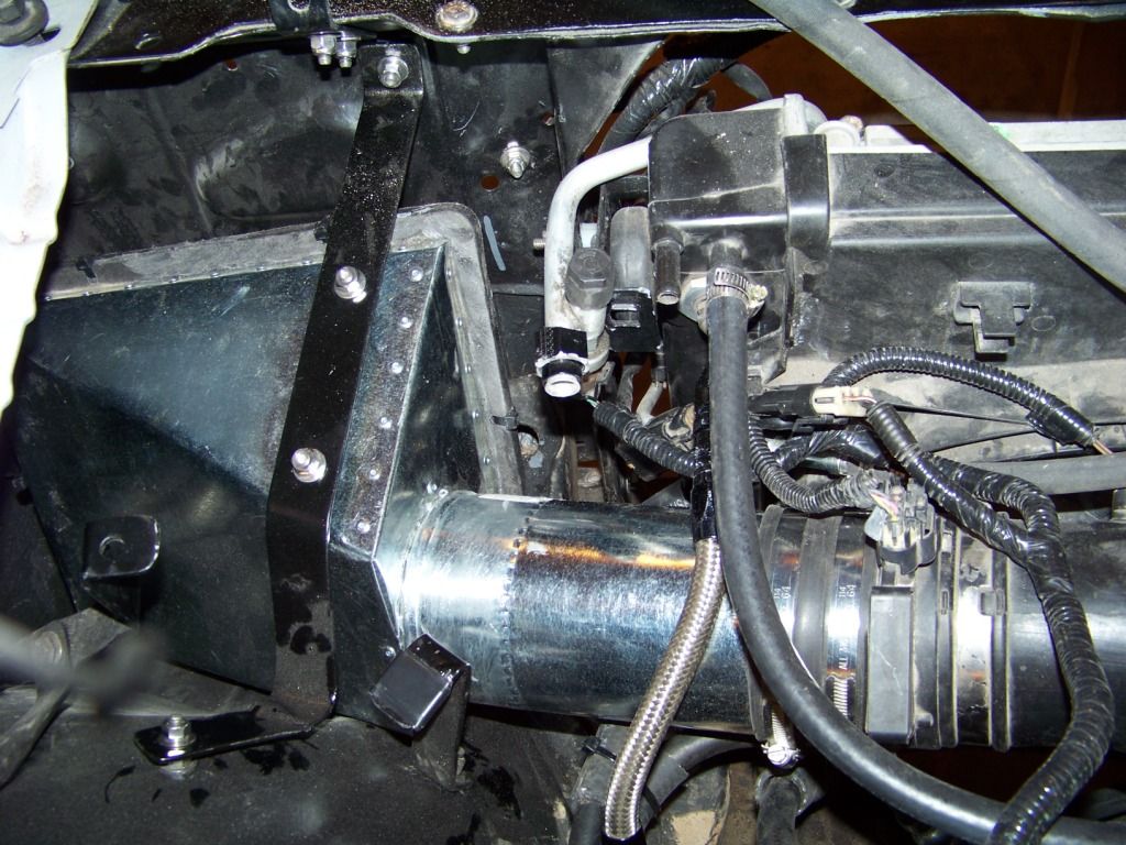
And finally this picture shows the completed air cleaner assembly installed in the Lemans. The air cleaner assembly just hangs below the bracket I made, all of this fits below the coolant recovery tank that is not installed here but was shown in the previous post on the cooling system. I got probably $20 into this, mostly for the duct parts.
Back under the hood, a few more things to take care of. This post covers my air cleaner solution. I looked into different tubing and filters but I found the parts and filters get expensive in a hurry. So once again I looked at using what I took off the GTO donor.
The picture below shows the air cleaner assembly from the GTO. Try as I might, I couldn�t fit this large shape anywhere under the hood of the Lemans.
So after much fussing and cutting here is what I came up with. I chose the area under the coolant recovery tank between the core support and driver�s inner fender for the air cleaner location. I cut down the GTO air cleaner assembly to just an upper and lower frame to hold the air cleaner element and made a new sheet metal top for it as shown below. This material is just the thin sheet metal that is sold for ductwork at Lowes. This picture shows the sheet metal top before I riveted it together and the top frame of the GTO air cleaner assembly after I cut the top portion off.
The two pictures below show the top and bottom of the completed air cleaner assembly. The sheet metal top was riveted together and to the top frame of the GTO air cleaner assembly. A 4� duct collar and 4� duct were also purchased at Lowes and attached to the sheet metal top as shown with rivets. The top and bottom frames are held together with zip ties, when I replace the filter I will just cut them off and then install new ones.
I made the bracket shown below to support the new air cleaner assembly:
And finally this picture shows the completed air cleaner assembly installed in the Lemans. The air cleaner assembly just hangs below the bracket I made, all of this fits below the coolant recovery tank that is not installed here but was shown in the previous post on the cooling system. I got probably $20 into this, mostly for the duct parts.
02-20-2013, 06:18 AM
#78
TECH Fanatic
Good idea! You will get cold air off the back of the lights. Only caution is to watch for engine rock at your coupler. Vibrant makes hump couplers for this type of a situation. They can absorb quite a bit of stretch and flex.
02-20-2013, 06:43 AM
#79
Staging Lane
Thread Starter
oldgoat69:
Thanks for the heads up on the coupler, I found those at Summit. I never realized there was such a thing. If I have an issue with that I now know how to fix it!
Phil
Thanks for the heads up on the coupler, I found those at Summit. I never realized there was such a thing. If I have an issue with that I now know how to fix it!
Phil
02-21-2013, 04:17 PM
#80
Staging Lane
Thread Starter
Windshield Washer Tank
This post covers the fabrication and installation of the washer tank. Not the most exciting thing in the world, but it�s the one of the last things to be installed under the hood and that area is DONE!
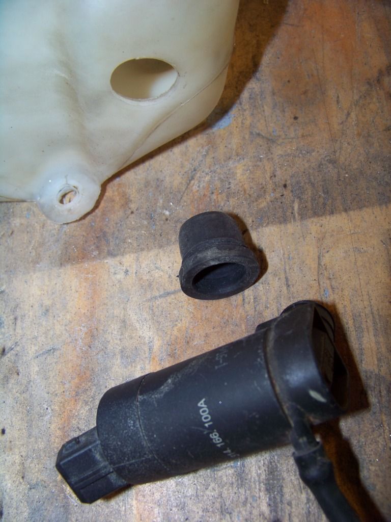
Following with my theme I used existing parts as much as possible. The washer tank from the GTO donor was an odd shape which I couldn�t get to work. I used parts from that tank along with the tank from the Lemans to make my own combination. The picture below shows the tank from the Lemans and the filler neck and washer pump from the GTO donor.
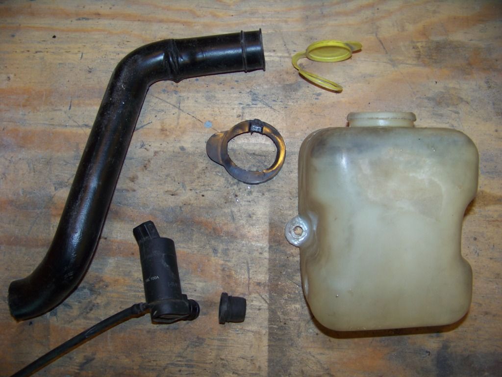
The washer pump from the GTO fits into a hole in the tank with a rubber grommet/filter screen. I just drilled the appropriate sized hole in the side of the Lemans tank and pushed the grommet and pump in.
The only area left under the hood was under and to the outside of the battery on the passenger side. This view shows that area with the passenger fender removed. I had to lengthen the harness slightly to get the connector to reach.
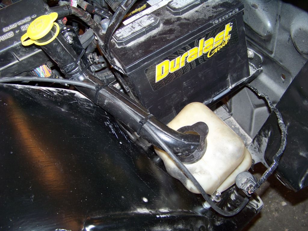
I removed the squirter nozzles from the GTO�s hood and hope to install those into the Lemans hood.
This post covers the fabrication and installation of the washer tank. Not the most exciting thing in the world, but it�s the one of the last things to be installed under the hood and that area is DONE!
Following with my theme I used existing parts as much as possible. The washer tank from the GTO donor was an odd shape which I couldn�t get to work. I used parts from that tank along with the tank from the Lemans to make my own combination. The picture below shows the tank from the Lemans and the filler neck and washer pump from the GTO donor.
The washer pump from the GTO fits into a hole in the tank with a rubber grommet/filter screen. I just drilled the appropriate sized hole in the side of the Lemans tank and pushed the grommet and pump in.
The only area left under the hood was under and to the outside of the battery on the passenger side. This view shows that area with the passenger fender removed. I had to lengthen the harness slightly to get the connector to reach.
I removed the squirter nozzles from the GTO�s hood and hope to install those into the Lemans hood.