
88 Fiero Formula LS4/F40 6 speed swap


 10-02-2012, 06:08 PM
#43

Thanks!
Thanks!
This is strictly a hobby for me, which allows me to take my time. On rare occasions I have done engine swaps for other fiero owners, but that is usually done to help fund another project. For example in the middle of this 2 year project, I set it aside and spent about 5 months doing a 383 SBC/Getrag swap in another fiero.
Thanks! I still have a lot to learn with metal fabrication and machining... that's what keeps it fun!
I will probably be bogged down with the harness work for the next couple of weeks, but I can share some of the details for other areas of the car.
This is strictly a hobby for me, which allows me to take my time. On rare occasions I have done engine swaps for other fiero owners, but that is usually done to help fund another project. For example in the middle of this 2 year project, I set it aside and spent about 5 months doing a 383 SBC/Getrag swap in another fiero.
I will probably be bogged down with the harness work for the next couple of weeks, but I can share some of the details for other areas of the car.
10-02-2012, 06:30 PM
#44
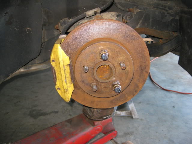
Since the LS4 should provide ample acceleration, I needed to do something to enhance the braking performance. The stock 88 brakes are decent with 10 1/2" vented rotors on all 4 corners, but they are prone to fade if used hard or from high speeds.
On my SBC/Getrag 88 Fiero, I ran a 12" C4 corvette rotor upgrade. It was a good improvement, but the rotors were less than an ideal fit and required clearancing the nose of the lower a-arm and notching the upper a-arm on lowered Fieros. So I set out to find another rotor that would retain the stock calipers, brake bias and parking brake, with a 12+" diameter to improve the calipers braking leverage.
After an exhaustive search, I found some 13" brake rotors that were a perfect fit without any additional clearancing and that worked with the stock brake calipers.
I had to redrill the rotors to the fiero pattern, design/fabricate the caliper brackets, centering rings, and the parking brake hardware (effectively lengthen the stock cables). It was a fun side project and they look awesome!
Stock:
Adapter bracket and ring:
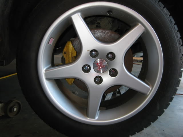
New 13" rotors:
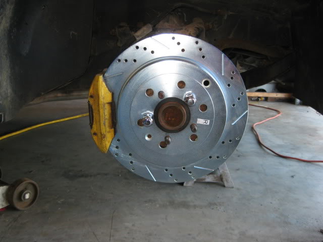
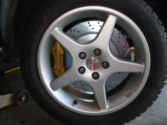
(yes that is a 13" rotor shoe horned in a 16" wheel).
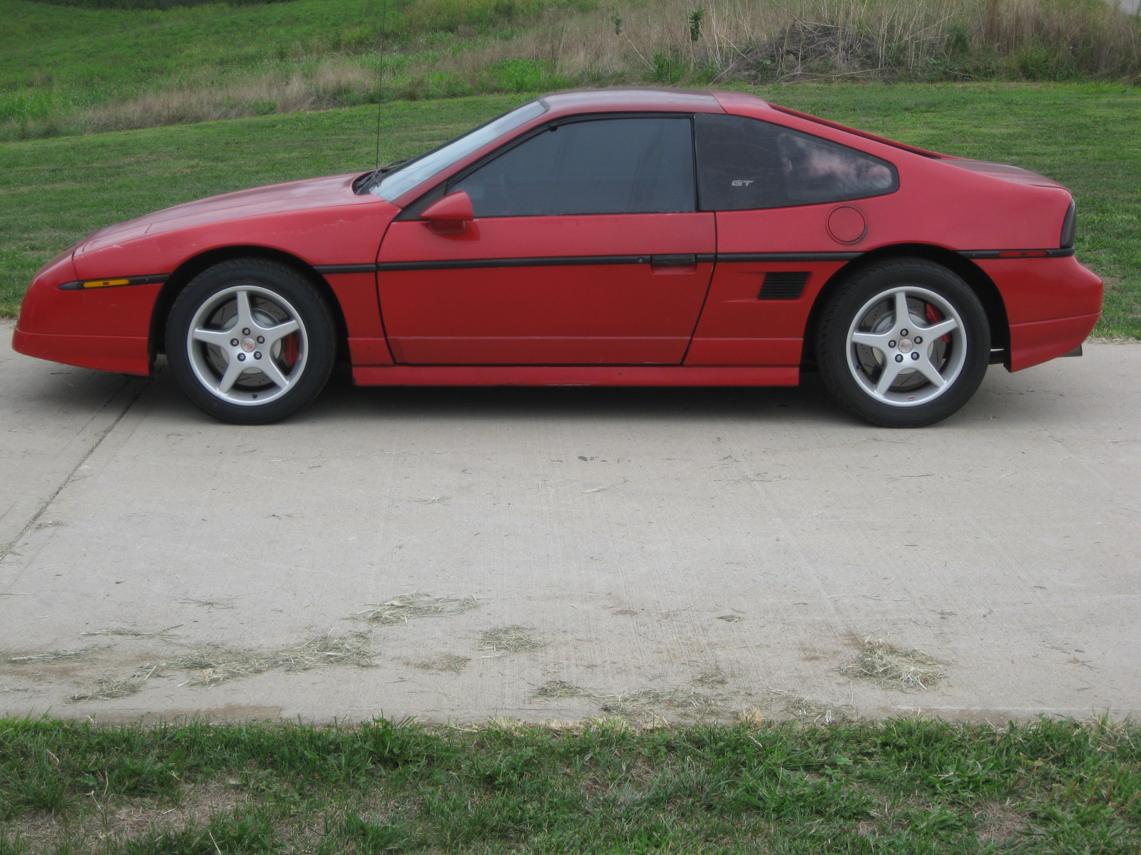
Since the black fiero hasn't been mobile, I also installed the 13" brake kit on my daily driver 88 Fiero GT (clone - it has a 4cyl/auto):
This upgrade keeps the factory brake bias front/rear, retains the factory parking brake function, and improves the braking leverage at the caliper by 29% and increases the rotor/pad surface by 20% to help reduce fade.
This has been a phenomenal upgrade for my daily driver!
On my SBC/Getrag 88 Fiero, I ran a 12" C4 corvette rotor upgrade. It was a good improvement, but the rotors were less than an ideal fit and required clearancing the nose of the lower a-arm and notching the upper a-arm on lowered Fieros. So I set out to find another rotor that would retain the stock calipers, brake bias and parking brake, with a 12+" diameter to improve the calipers braking leverage.
After an exhaustive search, I found some 13" brake rotors that were a perfect fit without any additional clearancing and that worked with the stock brake calipers.
I had to redrill the rotors to the fiero pattern, design/fabricate the caliper brackets, centering rings, and the parking brake hardware (effectively lengthen the stock cables). It was a fun side project and they look awesome!
Stock:
Adapter bracket and ring:
New 13" rotors:
(yes that is a 13" rotor shoe horned in a 16" wheel).
Since the black fiero hasn't been mobile, I also installed the 13" brake kit on my daily driver 88 Fiero GT (clone - it has a 4cyl/auto):
This upgrade keeps the factory brake bias front/rear, retains the factory parking brake function, and improves the braking leverage at the caliper by 29% and increases the rotor/pad surface by 20% to help reduce fade.
This has been a phenomenal upgrade for my daily driver!
 10-13-2012, 06:30 PM
#46
Thanks!
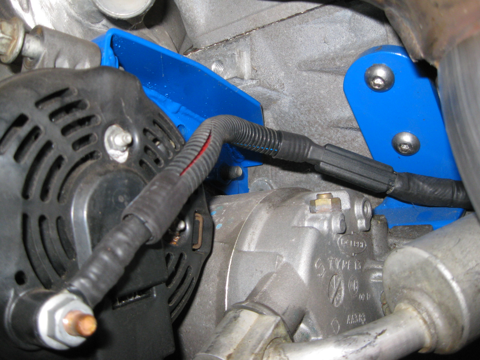
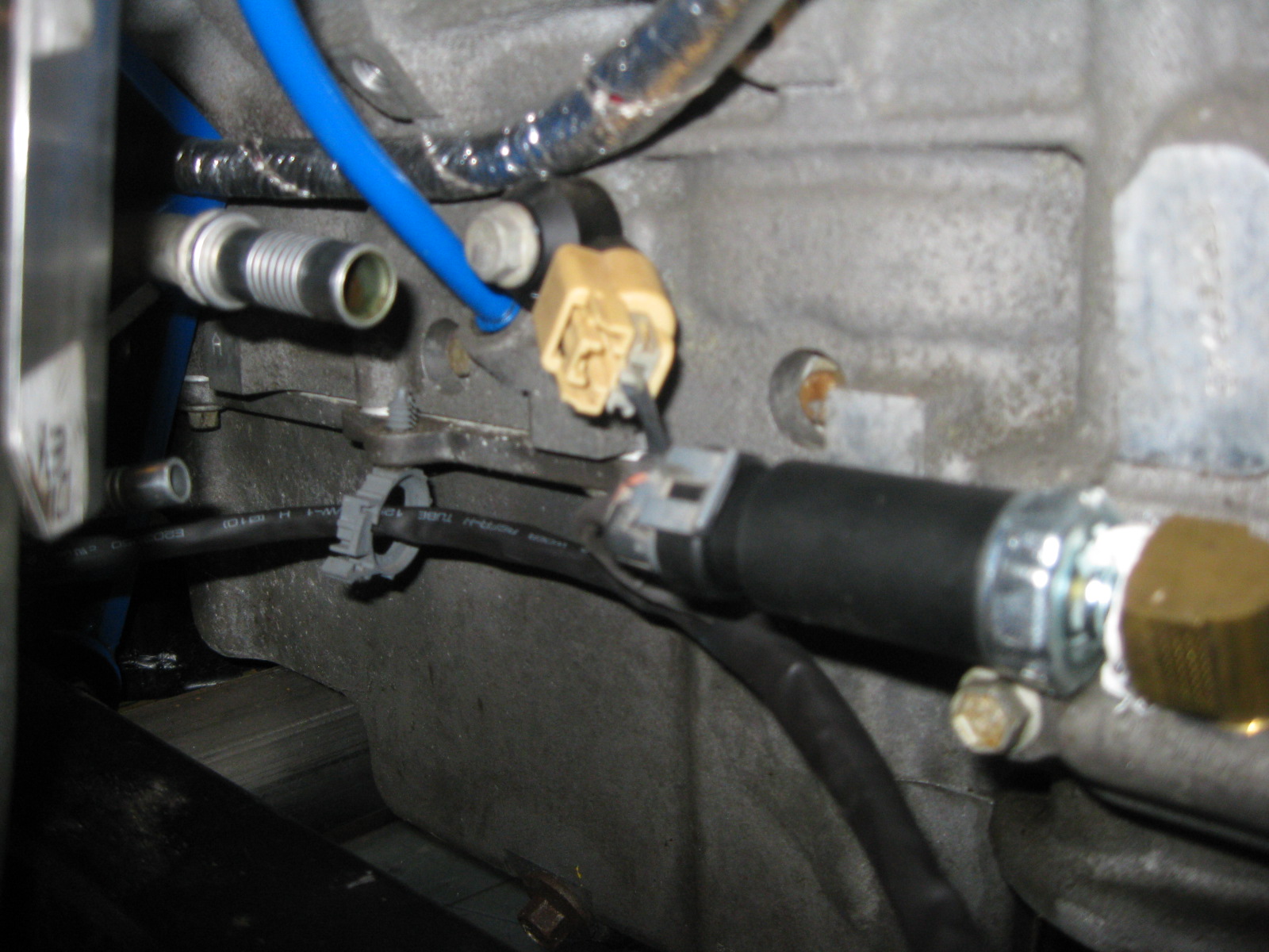
Did some more on the wiring harness. Everything is loomed up from the rear, over the top and to the front of the engine. Just need to loom up the Alt, AC, B1 knock and oil pressure sender, then I will start the termination process at the ecm.
The radiator arrived last week as well, just need to do some minor tweaks to the stock radiator mounts to install it. It is a 3 core rated for 450 hp.
10-13-2012, 06:35 PM
#47
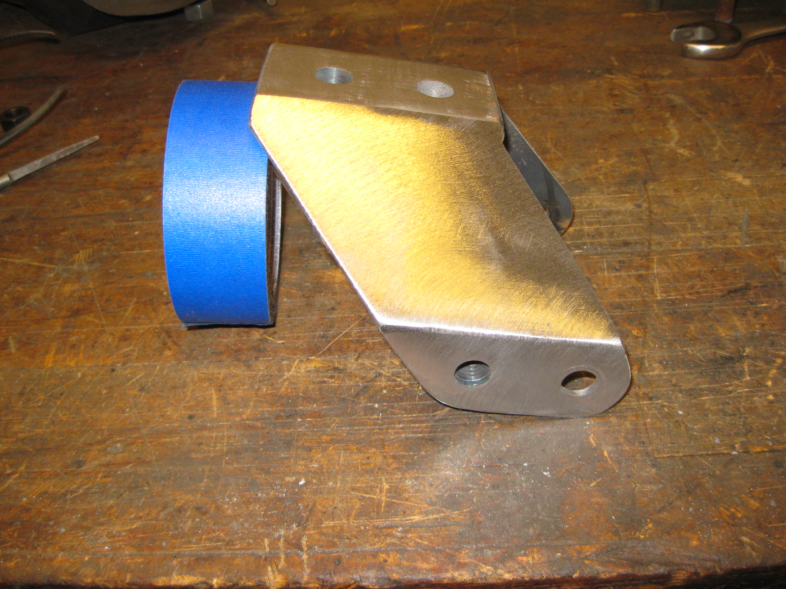
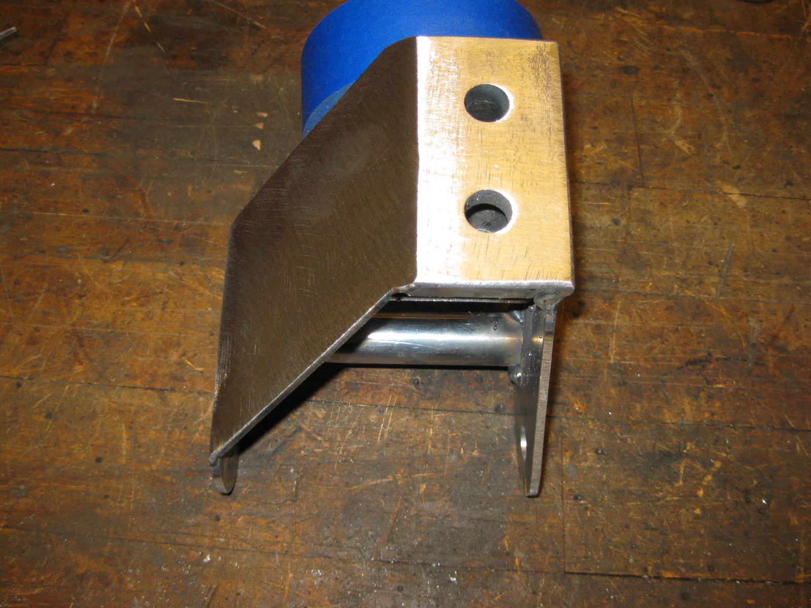
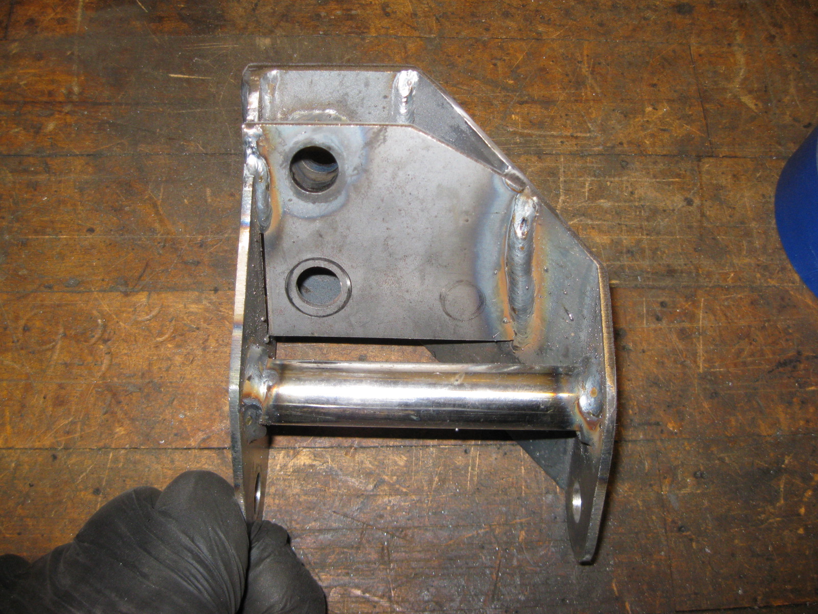
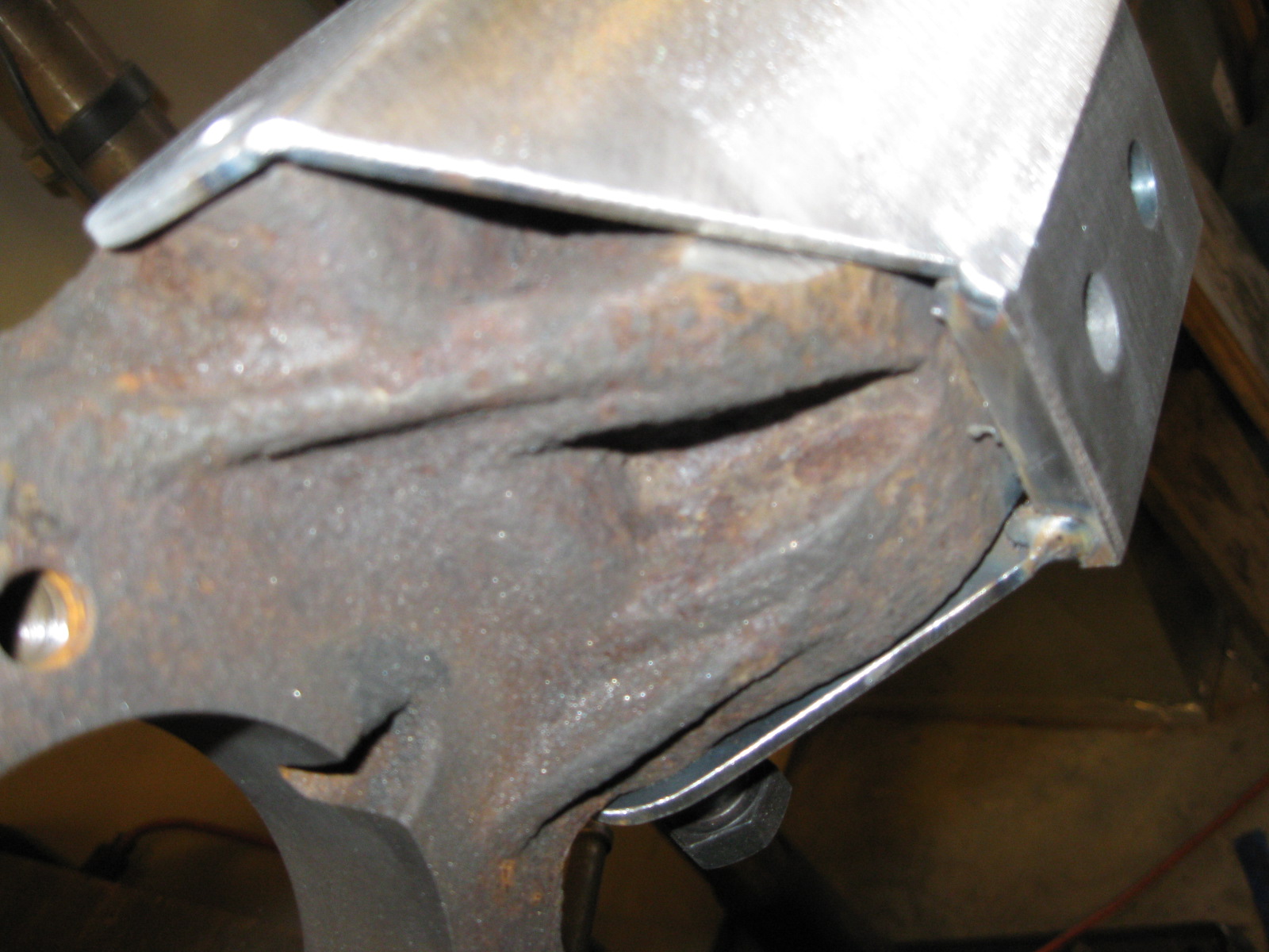
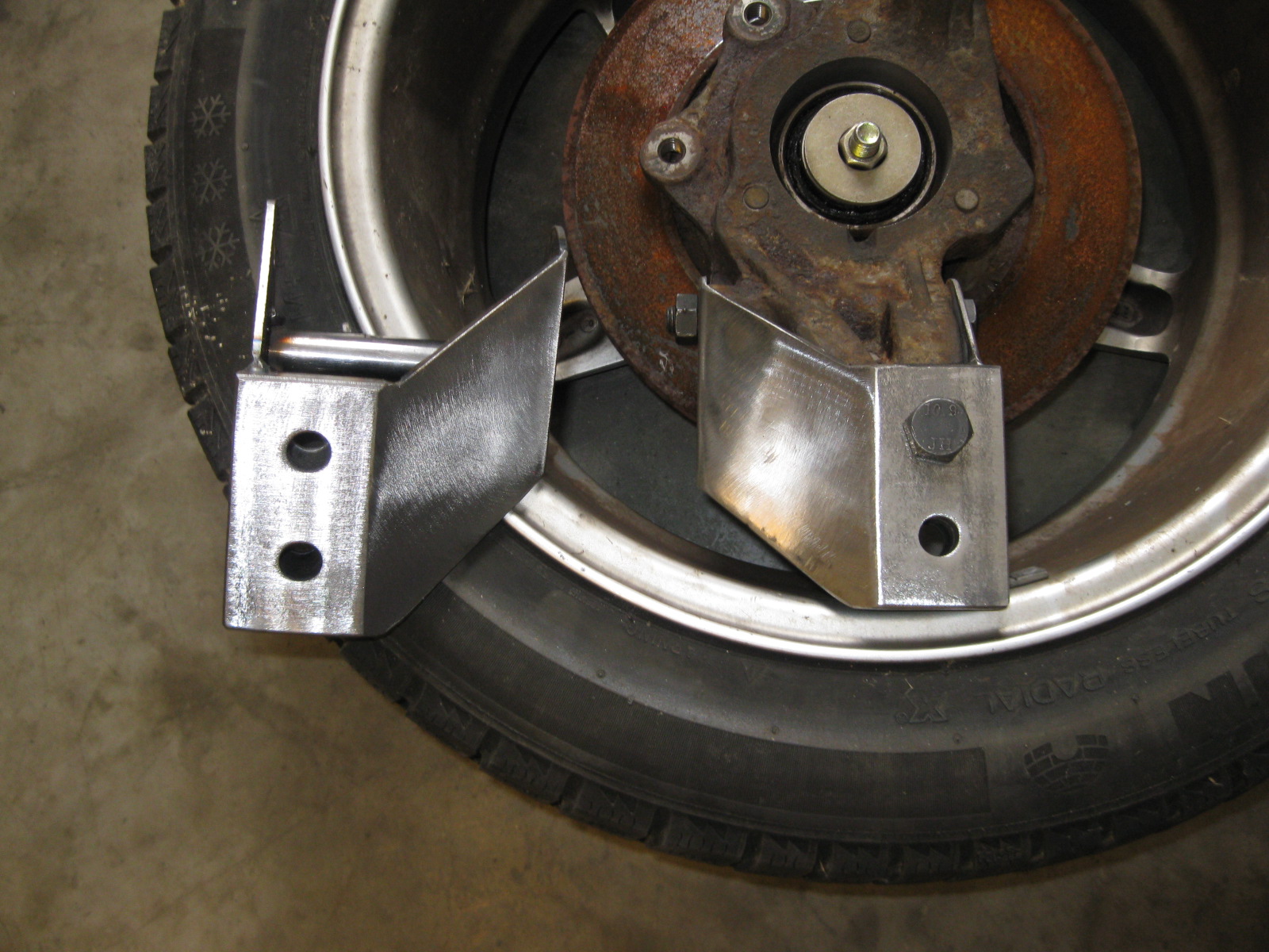
Along with designing a brake upgrade for this car, I also developed a rear camber correction kit for when the fiero is lowered.
This bracket relocates the lateral link (and trailing link) connection points at the upright 1 1/2" lower. So when installed on a Fiero that is lowered 1 1/2", the stock geometry is restored. If installed on a stock height Fiero, then the rear camber curve is improved (more negative camber gain under compression).
Here are some pictures showing the stock geometry at stock height & lowered 1 1/2" and this kit installed at stock height and lowered 1 1/2".
Stock Fiero at stock ride height (near level lateral links):
Stock Fiero lowered 1 1/2" (very poor geometry)
Fiero lowered 1 1/2" with the lateral link relocation bracket installed (geometry restored to stock ride height):
Fiero at stock ride height with the lateral link relocation bracket installed (more favorable geometry with improved camber curve):
Here are some various pictures of the relocation brackets:
10-13-2012, 06:44 PM
#48
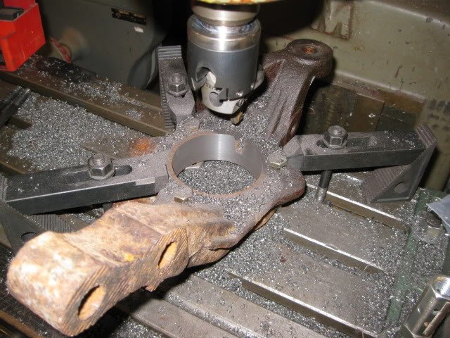
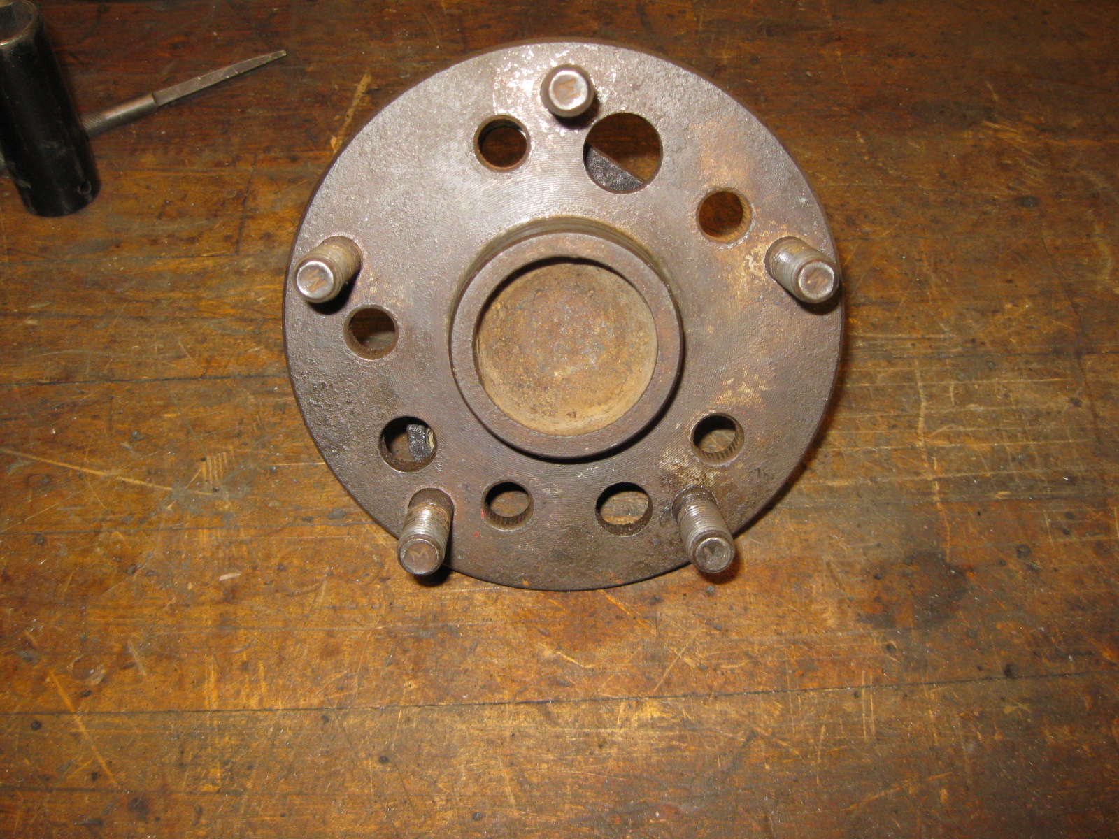
Eventually, this fiero will also have the widest possible rear wheels tucked under the stock body. The fiero comes stock with 7" rear wheels and I wanted to run some 10 1/2" wide wheels in the rear.
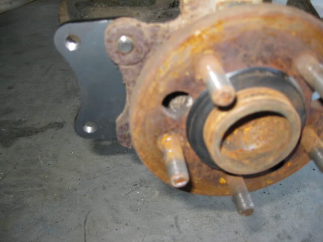
First order of business was to change the rear bolt pattern to 5 x 4 3/4. This change will give me a larger wheel bearing, larger 27 spline, and gives a wide selection of relatively cheap wide wheels.
So the rear fiero suspension upright and S10 4x4 wheel bearing were modified so they could be bolted together.
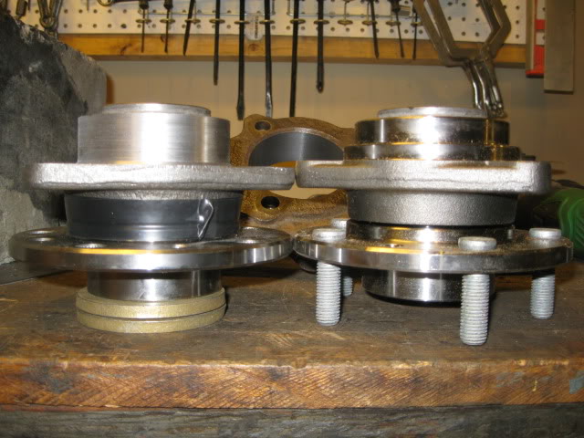
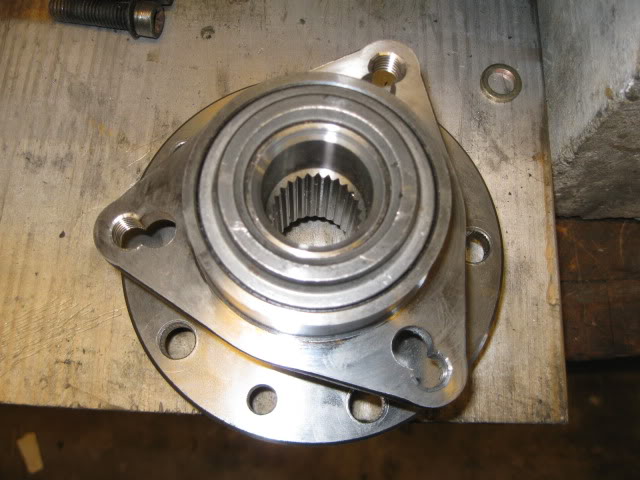
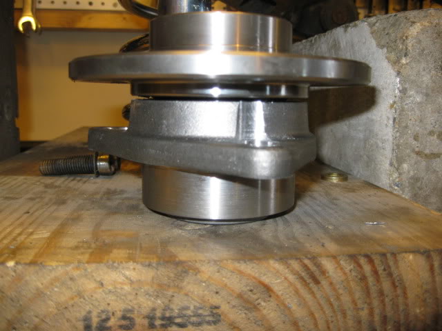
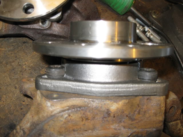
For the fronts, I just redrilled the wheel bearing flange for the 5 x 4 3/4":
First order of business was to change the rear bolt pattern to 5 x 4 3/4. This change will give me a larger wheel bearing, larger 27 spline, and gives a wide selection of relatively cheap wide wheels.
So the rear fiero suspension upright and S10 4x4 wheel bearing were modified so they could be bolted together.
For the fronts, I just redrilled the wheel bearing flange for the 5 x 4 3/4":
10-13-2012, 09:07 PM
#50

wow. I just read this thread and was impressed from the get go. You have given me some ideas to help get my car together faster, and you are an inspiration to all of us do it your selfers. Thank You for sharing what you have been doing. I can not wait to see the finished product!
Charlie
Charlie
10-18-2012, 05:54 PM
#51
wow. I just read this thread and was impressed from the get go. You have given me some ideas to help get my car together faster, and you are an inspiration to all of us do it your selfers. Thank You for sharing what you have been doing. I can not wait to see the finished product!
Charlie
Charlie
10-18-2012, 06:00 PM
#52
Spent the last week in the service manual gleaning what information I can about is needed for DoD to work. As I decide what to keep/omit in my harness, I wanted to know what all the inhibitors were for DoD activation. Here is a list:
1. Engine manifold vacuum low
2. Brake booster vacuum pressure low
3. Accelerator pedal position rate of increase too high, electronic throttle control
4. Accelerator pedal position too high, electronic throttle control
5. Ignition voltage out of range
6. Engine oil pressure out of range
7. Engine oil temperature out of range
8. Engine RPM out of range
9. Transmission gear incorrect
10. Transmission range incorrect
11. Transmission gear shift in progress
12. All cylinders activated via scan tool output control
13. Minimum time in V8 mode not met
14. Maximum V4 mode time exceeded
15. Engine oil aeration present
16. Decel fuel cutoff active
17. Fuel shut-off timer active
18. Minimum heater temp low, HVAC system
19. Reduced engine power active, electronic throttle control
20. Brake torque management active
21. Axle torque limiting active
22. Engine metal over temperature protection active
23. Catalytic converter over temperature protection active
24. Piston protection active, knock detected
25. Hot coolant mode
26. Engine over speed protection active
27. Fault active or Fault Pending - cylinder deactivation is disabled for the following faults:
*** Brake Booster Vacuum Sensor
*** Manifold Absolute Pressure Sensor
*** Engine Oil Pressure Sensor
*** Engine Coolant Temperature Sensor
*** Vehicle Speed Sensor
*** Crankshaft Position Sensor
*** Engine Misfire Detected
*** Cylinder Deactivation Solenoid Driver Circuit
As you can see the DoD setup is quite finicky and everything has to be in the programed ranges for it to work. Now as I try to get the system to work with a manual transmission, these are my 4 biggest concerns.
9. Transmission gear incorrect
10. Transmission range incorrect
11. Transmission gear shift in progress
*** Vehicle Speed Sensor
All communication about the transmission (Gear, Range or mid-shift) only happens through the High Speed GMLAN Serial Data Bus and there are no traditional inputs to the ECM for these. So if I need to fake the ECM into thinking it is in Drive, and 4th gear is engaged, then all that trickery has to happen on the TCM.
My concern about the VSS is that the two VSS wires go to the VSS and only a single VSS wire goes from the TCM to ECM (stock E67 LS4 calibration). Many other swaps using the E67 in a manual configuration were able to run both VSS wires directly to the ECM and get the Speedo to work, but the vehicle speed within the ECM (from a scanner) wouldn't show vehicle speed. The concern is if the ECM doesn't show the vehicle speed, will it enable DoD, or is it even looking for the VSS approval from the ECM, or does it come from the TCM through the High Speed GMLAN Serial Data Bus...
Probably the safest bet it to plan on installing the TCM in the center console area...
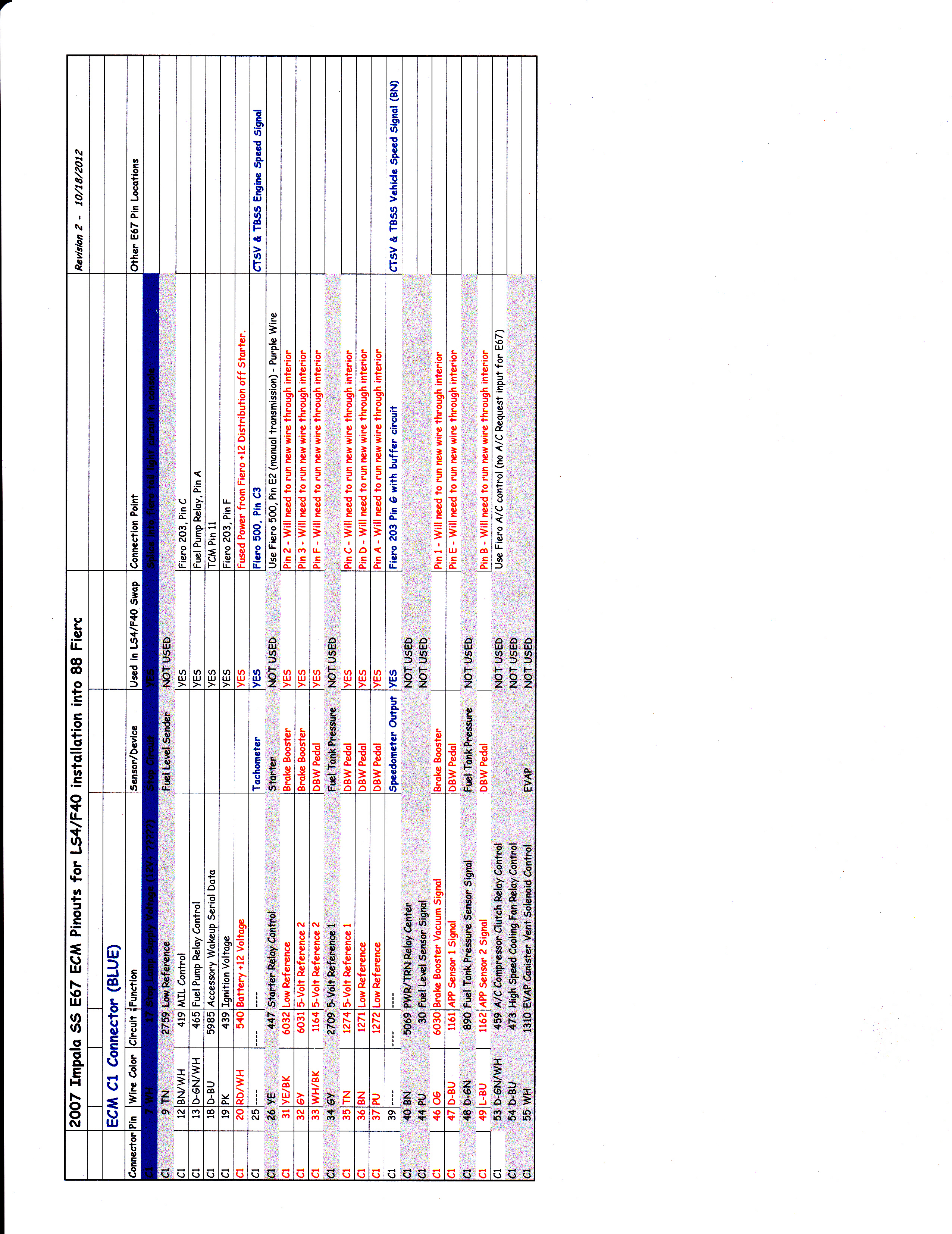
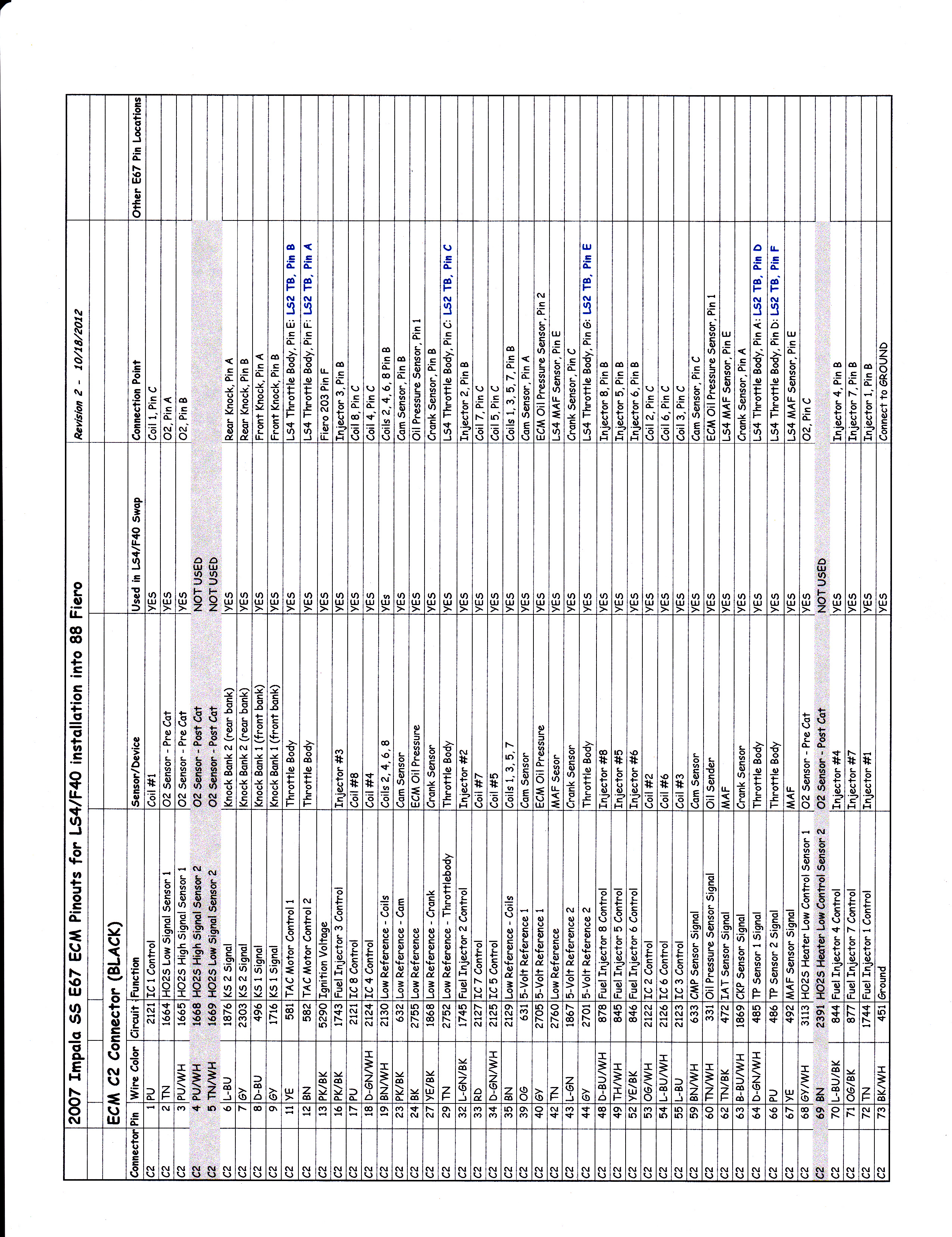
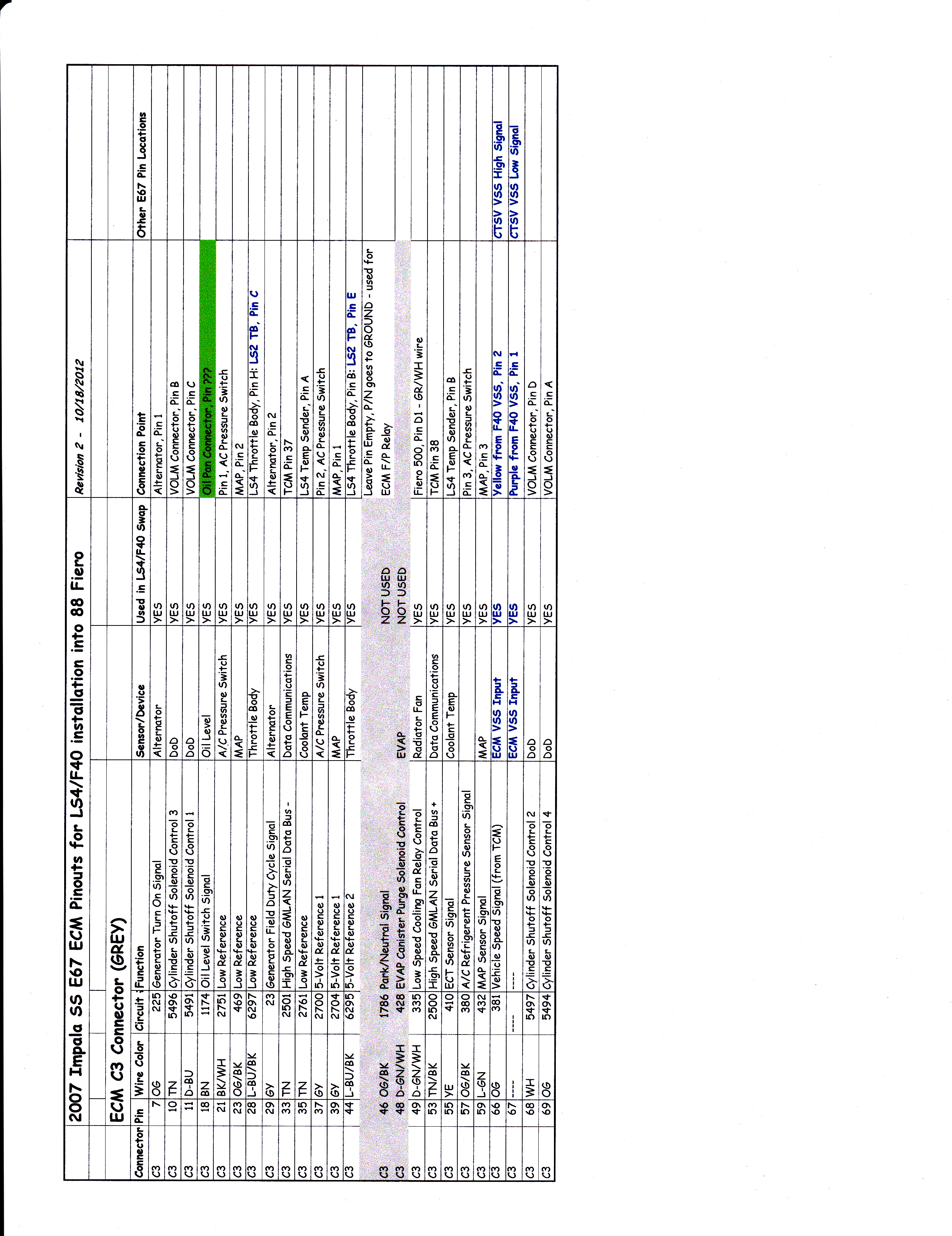
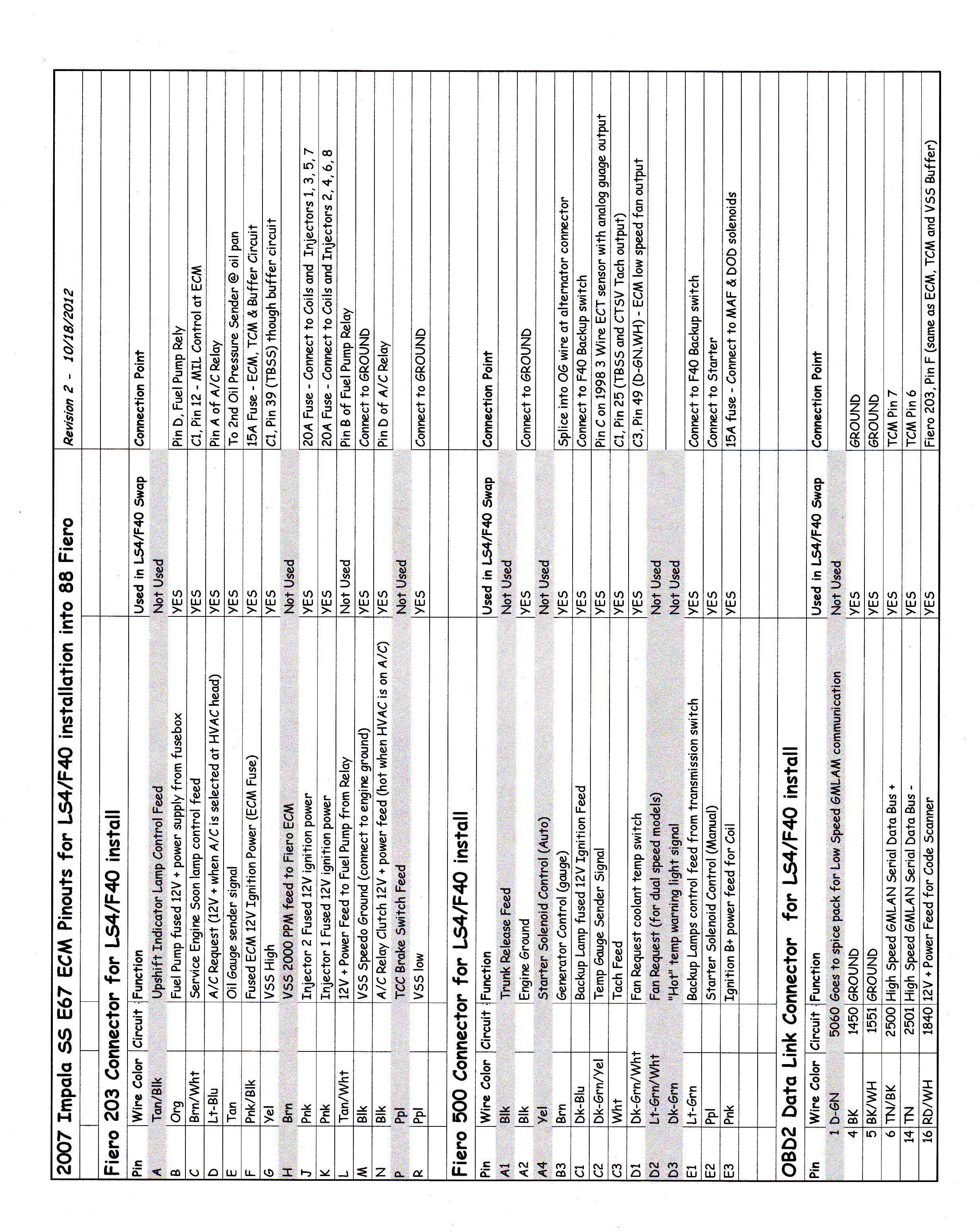
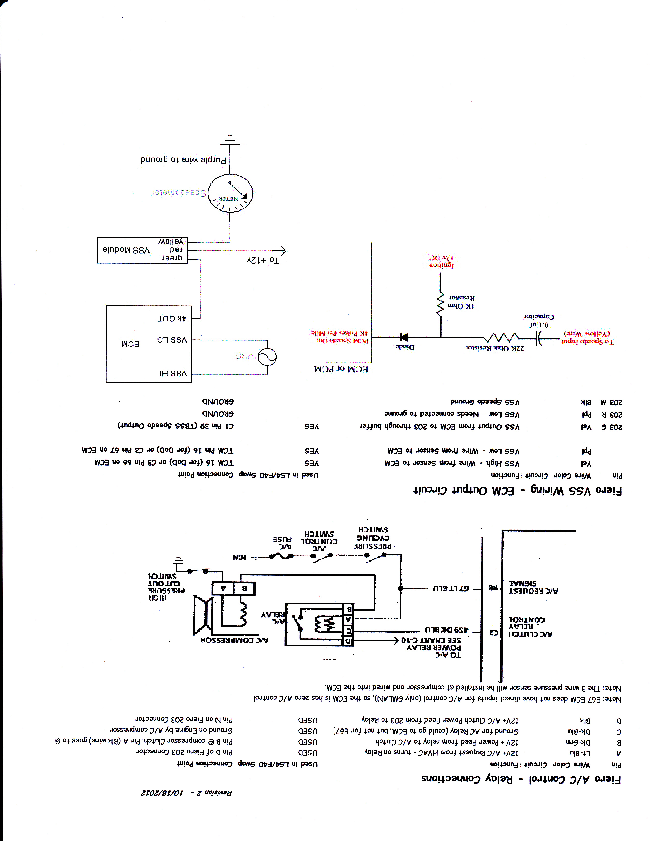
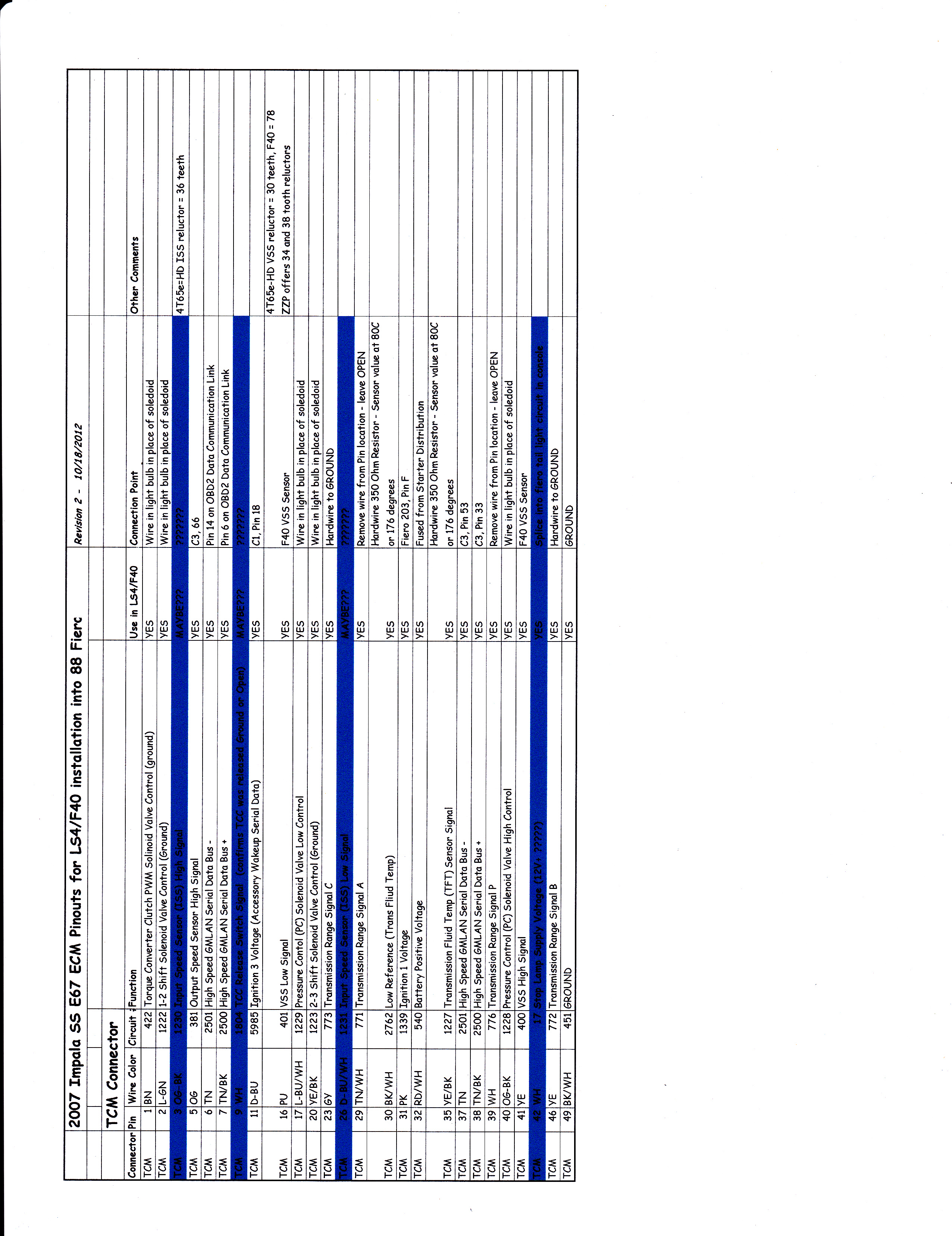
Here are the wiring charts I have created for this swap. It details the termination at the ECM as well as every connector with the Fiero connectors integrated. As you can see there are a few things I have to finalize with these charts.
The electrical circuit side is one of my weaknesses... so as I look at what I can do to fool the TCM into thinking the 4T65e-hd is still present and working, I am taking a rather simplistic approach... and likely doing some things wrong. Any TCM circuit experts feel free to provide other suggestions.
The major unknown right now is how much of the TCM functions have to be correct in order for the TCM to give the ECM the go ahead for DoD activation. So at this point I am planning to error on the side of doing too much (I can always remove them later) vs. not doing enough and having to revisit the issue. The chart below has the majority of my thoughts/plans, but a high level plan of action:
1: Hard wire the inputs from the Range Selections so the TCM see's the transmission in DRIVE
2: All solenoid circuits wired up with fiero side marker light bulbs so they will see a load.
3: Wire up the fluid Temp with a resistor so the TCM thinks the transmission is at about 175 degrees
4: Connect all the normal wires between the TCM/ECM and external inputs as normal
Once those are done, I am down to two issues.
The VSS could be connected from the F40 to the TCM.... But then the TCM will see the 60Kppm vs 24K... Might just add a 30 tooth reluctor on the tripod housing or intermediate shaft (unless I can just progam the TCM to look for the 60K ppm input).
The ISS... only way to mimic this signal is to add a reluctor to the transmission input shaft... which won't be easy. I could added it to the engine crankshaft (possibly mill the OD of the flywheel or bolt it on the balancer), but not sure if the TCM will go nuts with the ISS seeing speed while the VSS is stationary (when stopped and the clutch in). The only time the 4T65e-hd sees this in Park/Neutral, but the TCM will not see the transmission in Park/Neutral).
Here is the updated TCM wiring details:
1. Engine manifold vacuum low
2. Brake booster vacuum pressure low
3. Accelerator pedal position rate of increase too high, electronic throttle control
4. Accelerator pedal position too high, electronic throttle control
5. Ignition voltage out of range
6. Engine oil pressure out of range
7. Engine oil temperature out of range
8. Engine RPM out of range
9. Transmission gear incorrect
10. Transmission range incorrect
11. Transmission gear shift in progress
12. All cylinders activated via scan tool output control
13. Minimum time in V8 mode not met
14. Maximum V4 mode time exceeded
15. Engine oil aeration present
16. Decel fuel cutoff active
17. Fuel shut-off timer active
18. Minimum heater temp low, HVAC system
19. Reduced engine power active, electronic throttle control
20. Brake torque management active
21. Axle torque limiting active
22. Engine metal over temperature protection active
23. Catalytic converter over temperature protection active
24. Piston protection active, knock detected
25. Hot coolant mode
26. Engine over speed protection active
27. Fault active or Fault Pending - cylinder deactivation is disabled for the following faults:
*** Brake Booster Vacuum Sensor
*** Manifold Absolute Pressure Sensor
*** Engine Oil Pressure Sensor
*** Engine Coolant Temperature Sensor
*** Vehicle Speed Sensor
*** Crankshaft Position Sensor
*** Engine Misfire Detected
*** Cylinder Deactivation Solenoid Driver Circuit
As you can see the DoD setup is quite finicky and everything has to be in the programed ranges for it to work. Now as I try to get the system to work with a manual transmission, these are my 4 biggest concerns.
9. Transmission gear incorrect
10. Transmission range incorrect
11. Transmission gear shift in progress
*** Vehicle Speed Sensor
All communication about the transmission (Gear, Range or mid-shift) only happens through the High Speed GMLAN Serial Data Bus and there are no traditional inputs to the ECM for these. So if I need to fake the ECM into thinking it is in Drive, and 4th gear is engaged, then all that trickery has to happen on the TCM.
My concern about the VSS is that the two VSS wires go to the VSS and only a single VSS wire goes from the TCM to ECM (stock E67 LS4 calibration). Many other swaps using the E67 in a manual configuration were able to run both VSS wires directly to the ECM and get the Speedo to work, but the vehicle speed within the ECM (from a scanner) wouldn't show vehicle speed. The concern is if the ECM doesn't show the vehicle speed, will it enable DoD, or is it even looking for the VSS approval from the ECM, or does it come from the TCM through the High Speed GMLAN Serial Data Bus...
Probably the safest bet it to plan on installing the TCM in the center console area...
Here are the wiring charts I have created for this swap. It details the termination at the ECM as well as every connector with the Fiero connectors integrated. As you can see there are a few things I have to finalize with these charts.
The electrical circuit side is one of my weaknesses... so as I look at what I can do to fool the TCM into thinking the 4T65e-hd is still present and working, I am taking a rather simplistic approach... and likely doing some things wrong. Any TCM circuit experts feel free to provide other suggestions.
The major unknown right now is how much of the TCM functions have to be correct in order for the TCM to give the ECM the go ahead for DoD activation. So at this point I am planning to error on the side of doing too much (I can always remove them later) vs. not doing enough and having to revisit the issue. The chart below has the majority of my thoughts/plans, but a high level plan of action:
1: Hard wire the inputs from the Range Selections so the TCM see's the transmission in DRIVE
2: All solenoid circuits wired up with fiero side marker light bulbs so they will see a load.
3: Wire up the fluid Temp with a resistor so the TCM thinks the transmission is at about 175 degrees
4: Connect all the normal wires between the TCM/ECM and external inputs as normal
Once those are done, I am down to two issues.
The VSS could be connected from the F40 to the TCM.... But then the TCM will see the 60Kppm vs 24K... Might just add a 30 tooth reluctor on the tripod housing or intermediate shaft (unless I can just progam the TCM to look for the 60K ppm input).
The ISS... only way to mimic this signal is to add a reluctor to the transmission input shaft... which won't be easy. I could added it to the engine crankshaft (possibly mill the OD of the flywheel or bolt it on the balancer), but not sure if the TCM will go nuts with the ISS seeing speed while the VSS is stationary (when stopped and the clutch in). The only time the 4T65e-hd sees this in Park/Neutral, but the TCM will not see the transmission in Park/Neutral).
Here is the updated TCM wiring details:
10-20-2012, 06:17 PM
#53
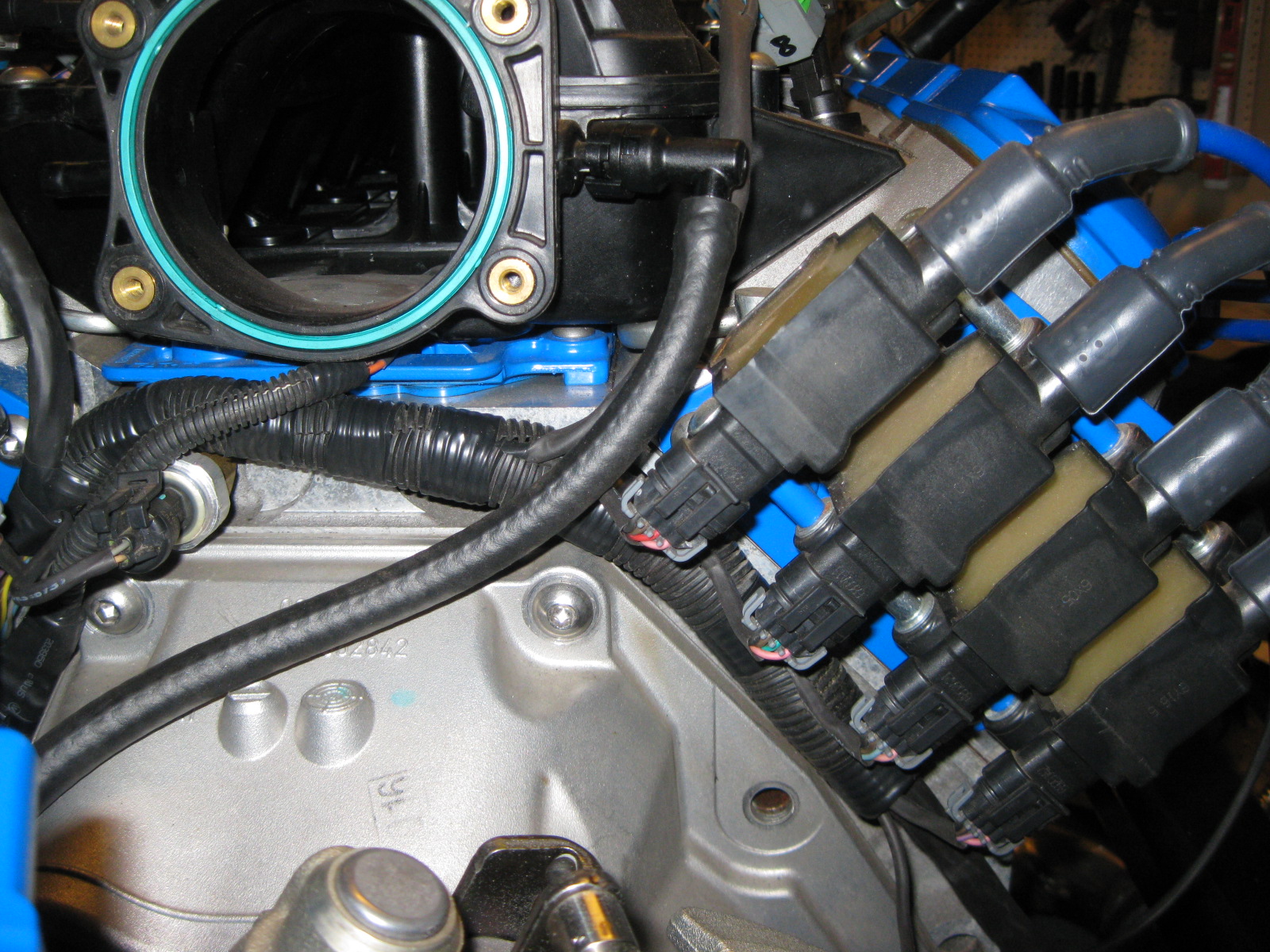
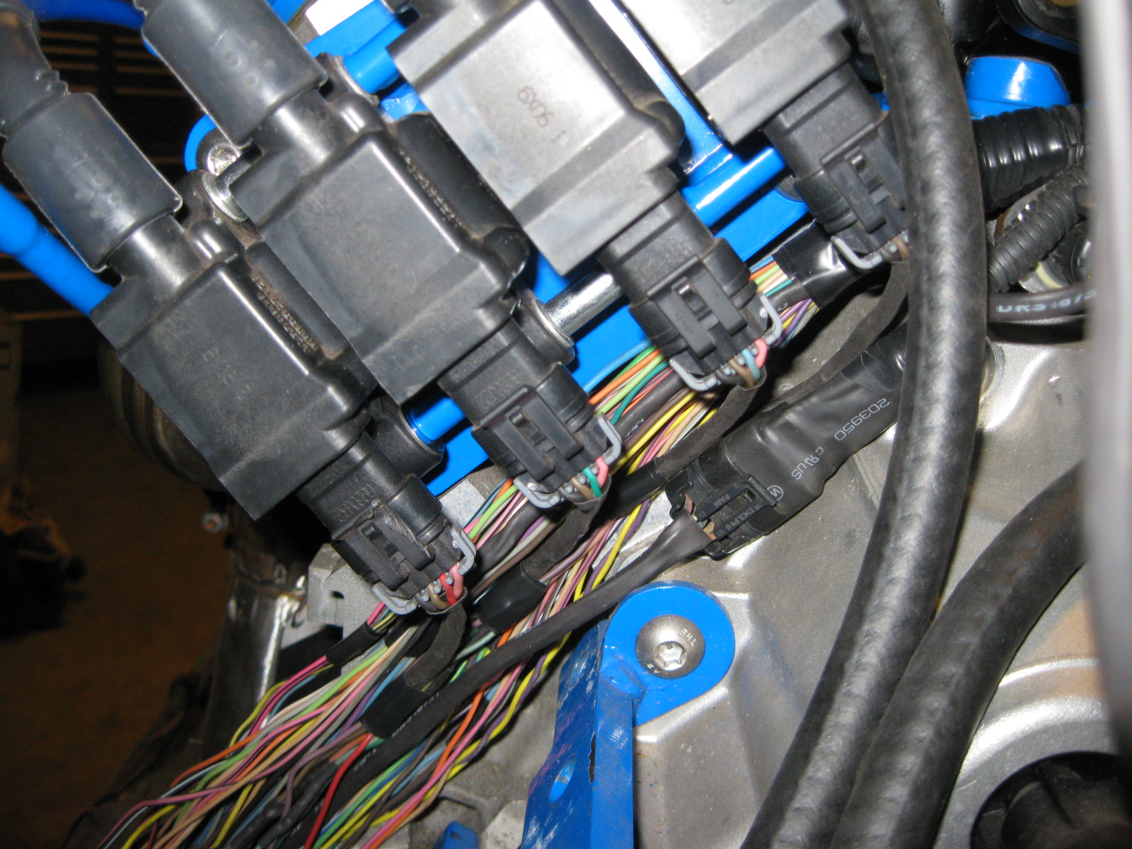
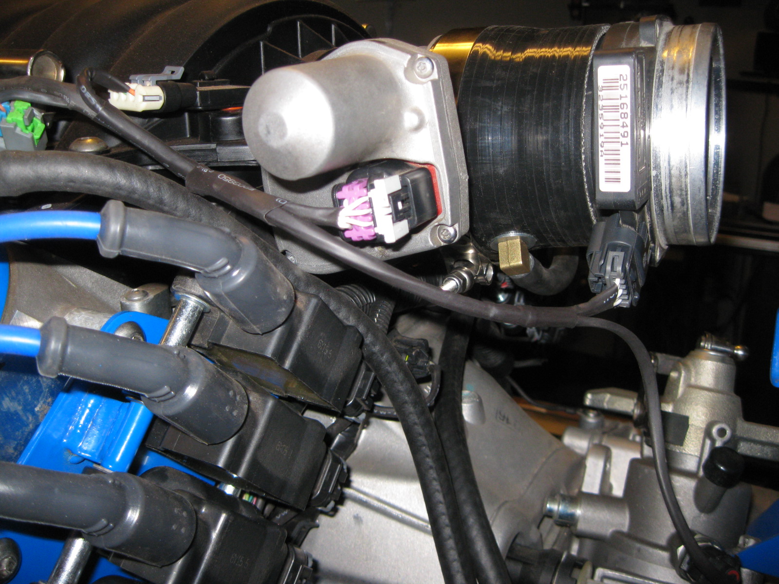
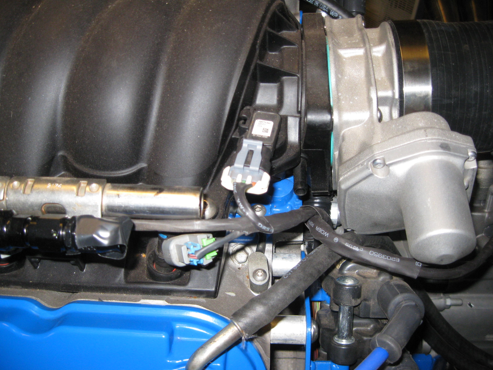
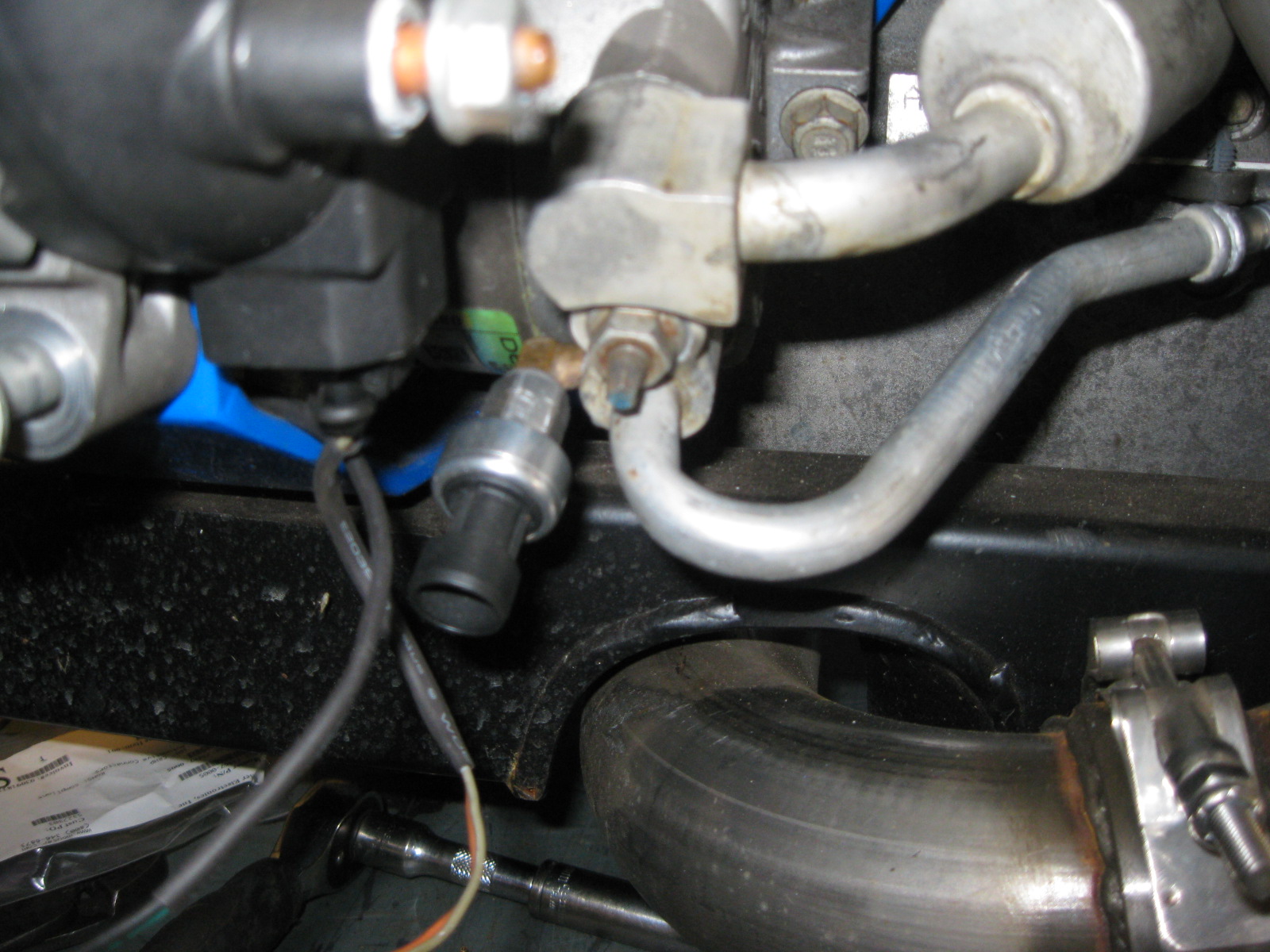
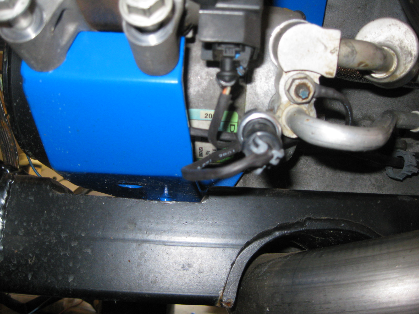
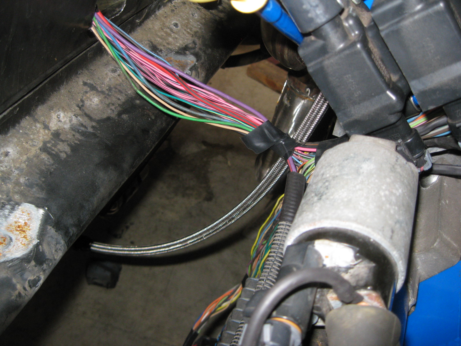
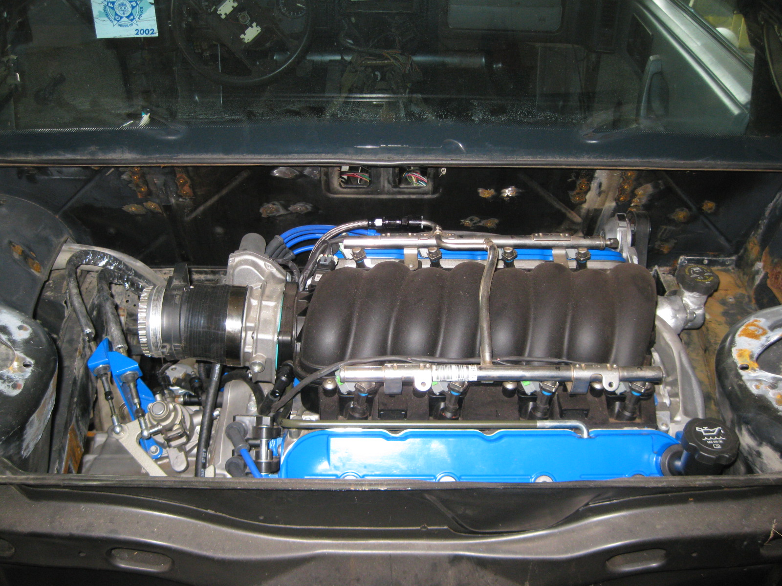
Getting closer to having the engine side of the harness done...
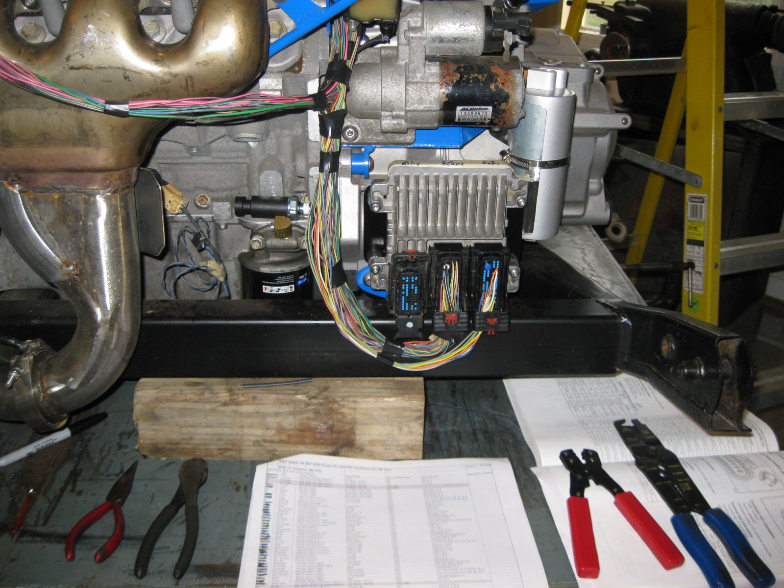
Hopefully on Sunday I will add in the A/C pressure sender and loom up the front harness containing the Alternator, A/C clutch, A/C pressure switch, Ground to engine, B1 Knock, Fiero Oil pressure sender and finish up the engine side of things. The wire bundle across the exhaust manifold is the portion of the harness that will enter the center console area (500, 203, TCM and A/C & fuel relay will all be in the center console area). I still need to add in the wires for the throttle pedal, brake booster sensor and the ones to the TCM.
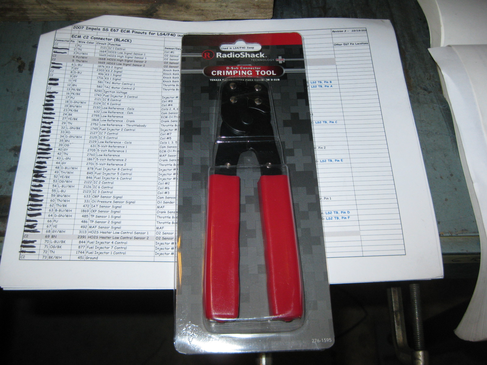
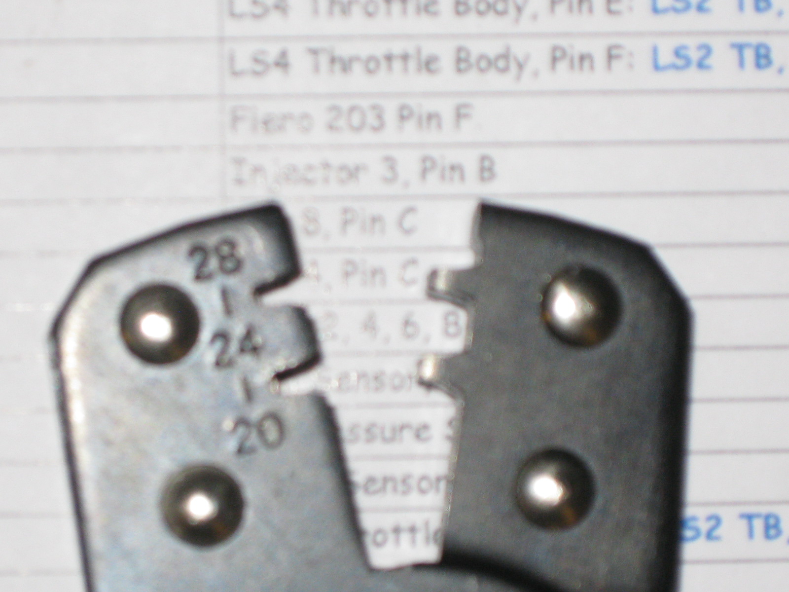
Re-pinning the terminals at the ECM takes a special crimp tool.
The professional version costs about $300,
The one from LSxTune is about $32, http://www.lsxtune.com/shop..._170/products_id/362
This one from radio shack is $9.99 and the one I have been using so far (ordered the LSxTune one as well):
I also found on the truck forum where they were tricking the T42 TCM's shift solenoids with a 1K resistor when swapping in a 4T80 (it had 1 less shift solenoid) so that is promising. They also had other swaps with the T42 TCM where they swapped in a transmission w/o the ISS sensor and were able to tune it out. I still need to check on some things. I may add a 2nd VSS sensor to the transmission and point it at the output shaft gear (22 tooth pinion that drives the 78 tooth ring gear). The 22 would be close to the 25 the TCM is looking for and may be close enough to make adjustments in the tune. Now I need to see if there is a good spot on the case to drill through to mount the sensor.
Hopefully on Sunday I will add in the A/C pressure sender and loom up the front harness containing the Alternator, A/C clutch, A/C pressure switch, Ground to engine, B1 Knock, Fiero Oil pressure sender and finish up the engine side of things. The wire bundle across the exhaust manifold is the portion of the harness that will enter the center console area (500, 203, TCM and A/C & fuel relay will all be in the center console area). I still need to add in the wires for the throttle pedal, brake booster sensor and the ones to the TCM.
Re-pinning the terminals at the ECM takes a special crimp tool.
The professional version costs about $300,
The one from LSxTune is about $32, http://www.lsxtune.com/shop..._170/products_id/362
This one from radio shack is $9.99 and the one I have been using so far (ordered the LSxTune one as well):
I also found on the truck forum where they were tricking the T42 TCM's shift solenoids with a 1K resistor when swapping in a 4T80 (it had 1 less shift solenoid) so that is promising. They also had other swaps with the T42 TCM where they swapped in a transmission w/o the ISS sensor and were able to tune it out. I still need to check on some things. I may add a 2nd VSS sensor to the transmission and point it at the output shaft gear (22 tooth pinion that drives the 78 tooth ring gear). The 22 would be close to the 25 the TCM is looking for and may be close enough to make adjustments in the tune. Now I need to see if there is a good spot on the case to drill through to mount the sensor.
10-21-2012, 02:19 PM
#54
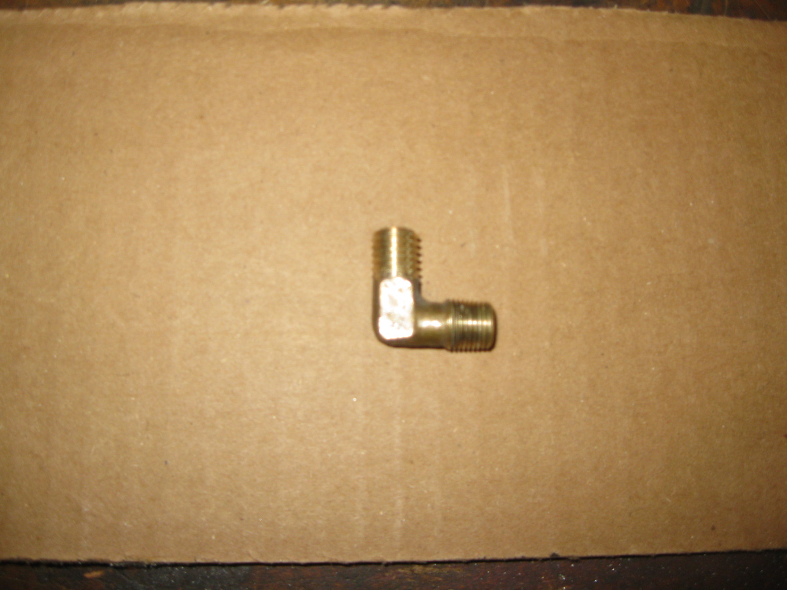
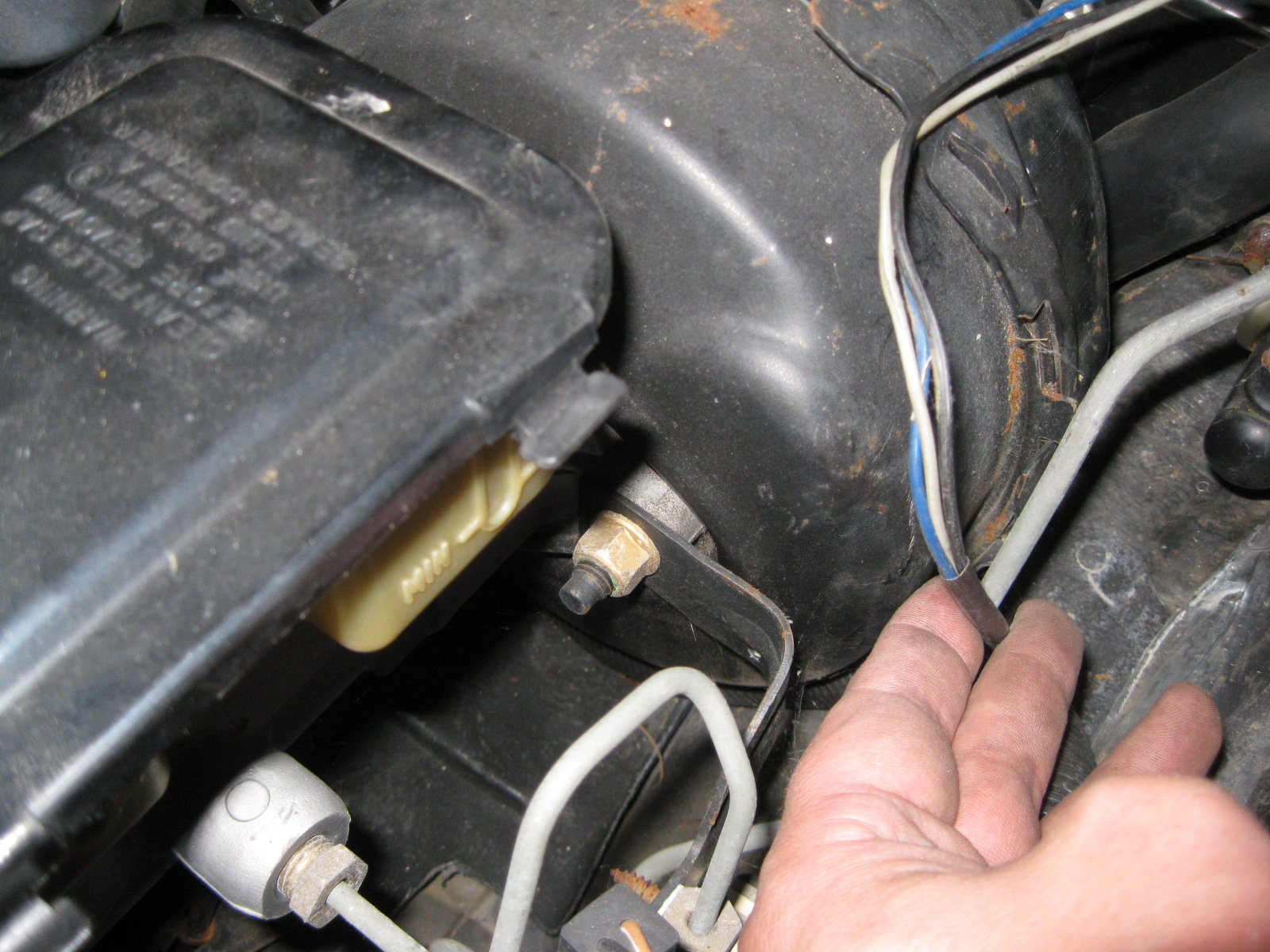
Installed the A/C pressure sender for the ECM. Found a brass fitting with a 1/8 NPT on one end and used a M10-1.5 die to rethread the other end. Then it was a matter of drilling/tapping the high side fitting at the compressor. I coated the threads with JB-Weld before threading them in to help ensure a leak free seal.
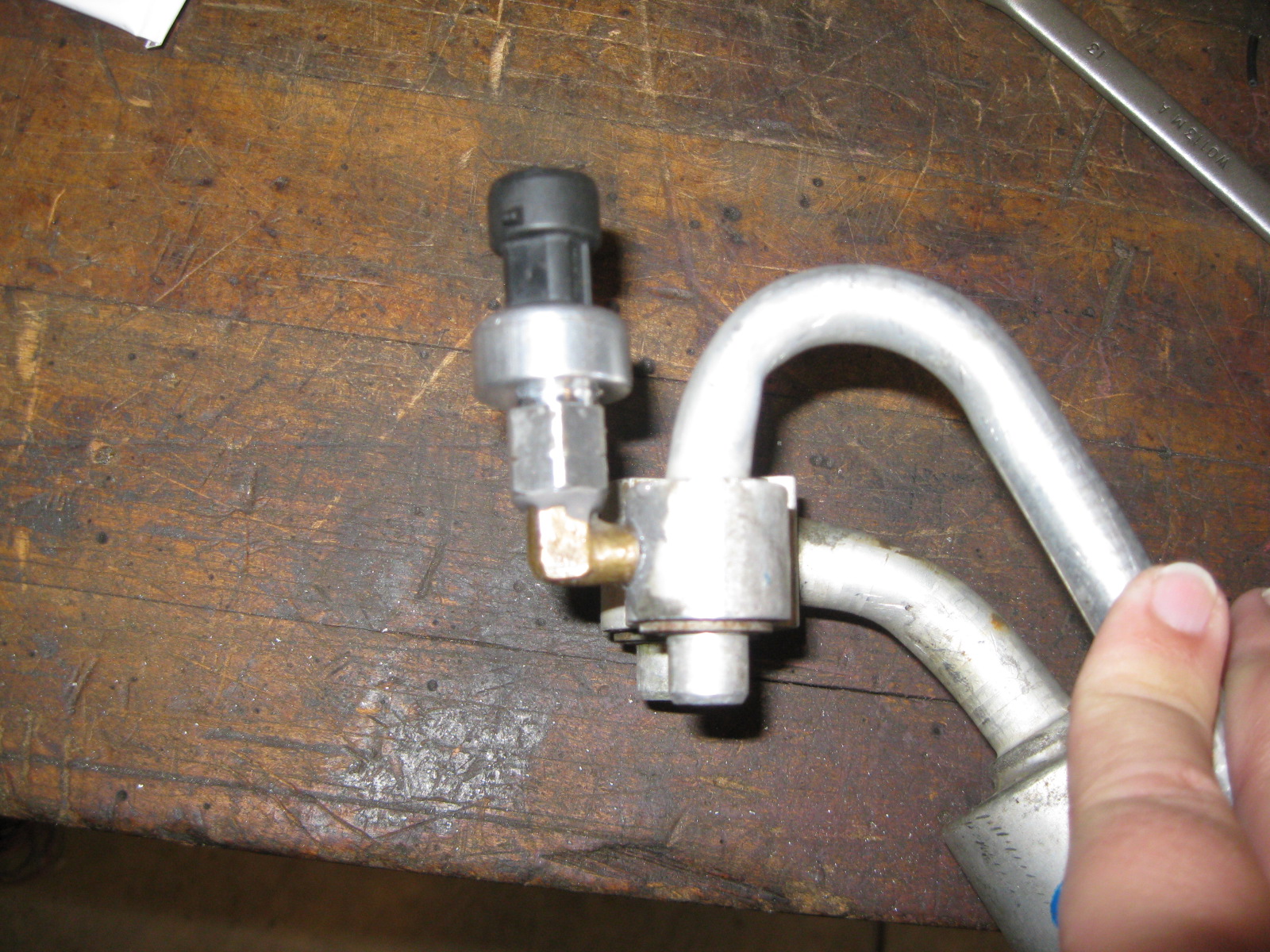
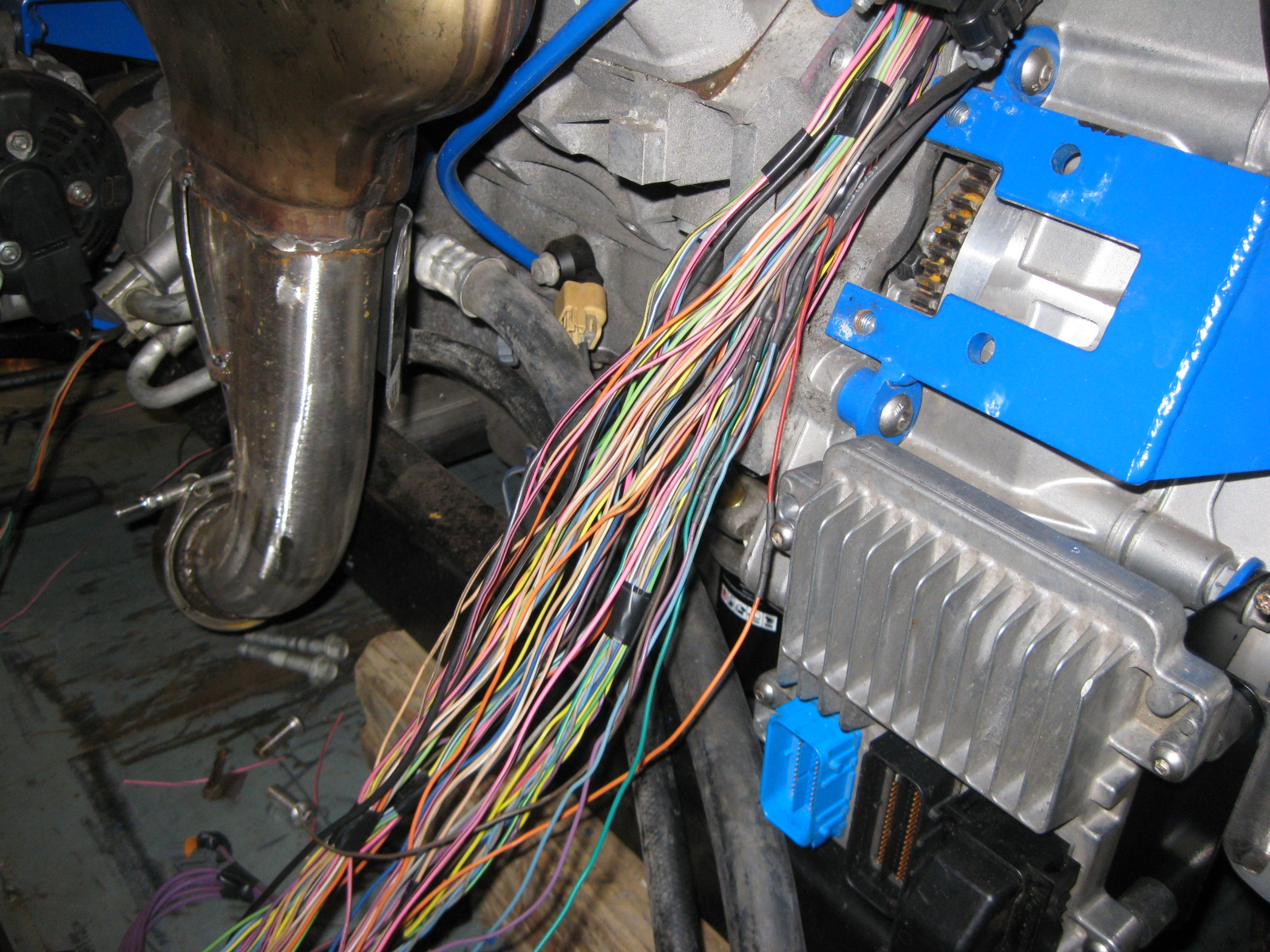
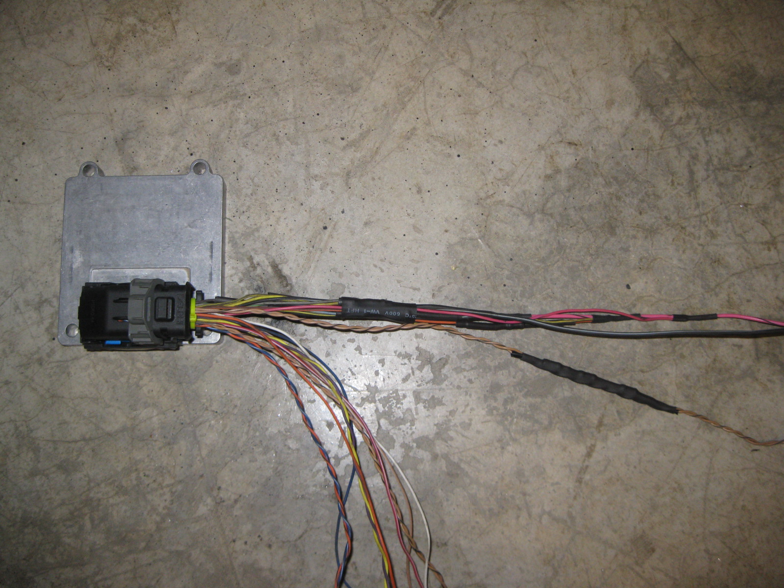
With the last engine sensor installed, I finished up the engine harness (except soldering on the starter terminal end):
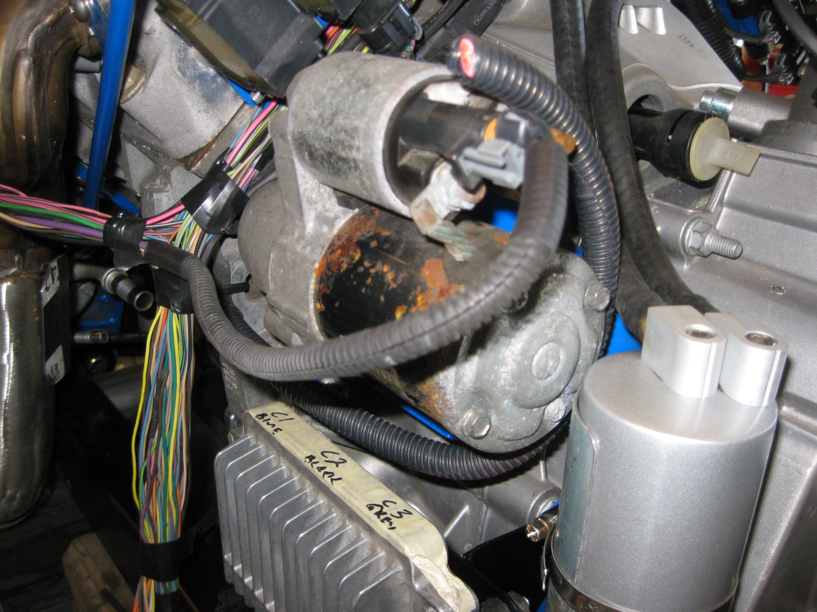
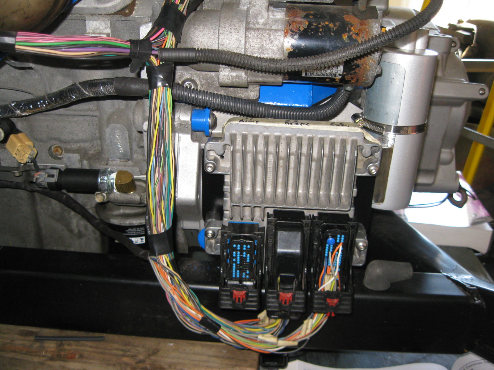
The center connector on the ECM is now fully compete. The other two still need quite a few wires from the other various components that will be in the console/foot well/brake booster area.
Next step is to reinstall the engine/transmission in the chassis and continue to finalize the wiring, fuel filter location, build the fuel line and mockup the coolant hoses. Then everything will come out again to finalize the engine bay.
With the last engine sensor installed, I finished up the engine harness (except soldering on the starter terminal end):
The center connector on the ECM is now fully compete. The other two still need quite a few wires from the other various components that will be in the console/foot well/brake booster area.
Next step is to reinstall the engine/transmission in the chassis and continue to finalize the wiring, fuel filter location, build the fuel line and mockup the coolant hoses. Then everything will come out again to finalize the engine bay.
 10-28-2012, 05:03 PM
#56
The F40 6 speed does not come with a LSD, but for about $1K you can buy one. I am not really a fan of LSD in Fieros, especially at $1K.
With the transverse layout, the driveline torque tries to lift the front wheels and both rear wheels are loaded about equal vs a front engine longitudinal setup that twists the chassis and unevenly loads the rear wheels.
10-28-2012, 05:06 PM
#57
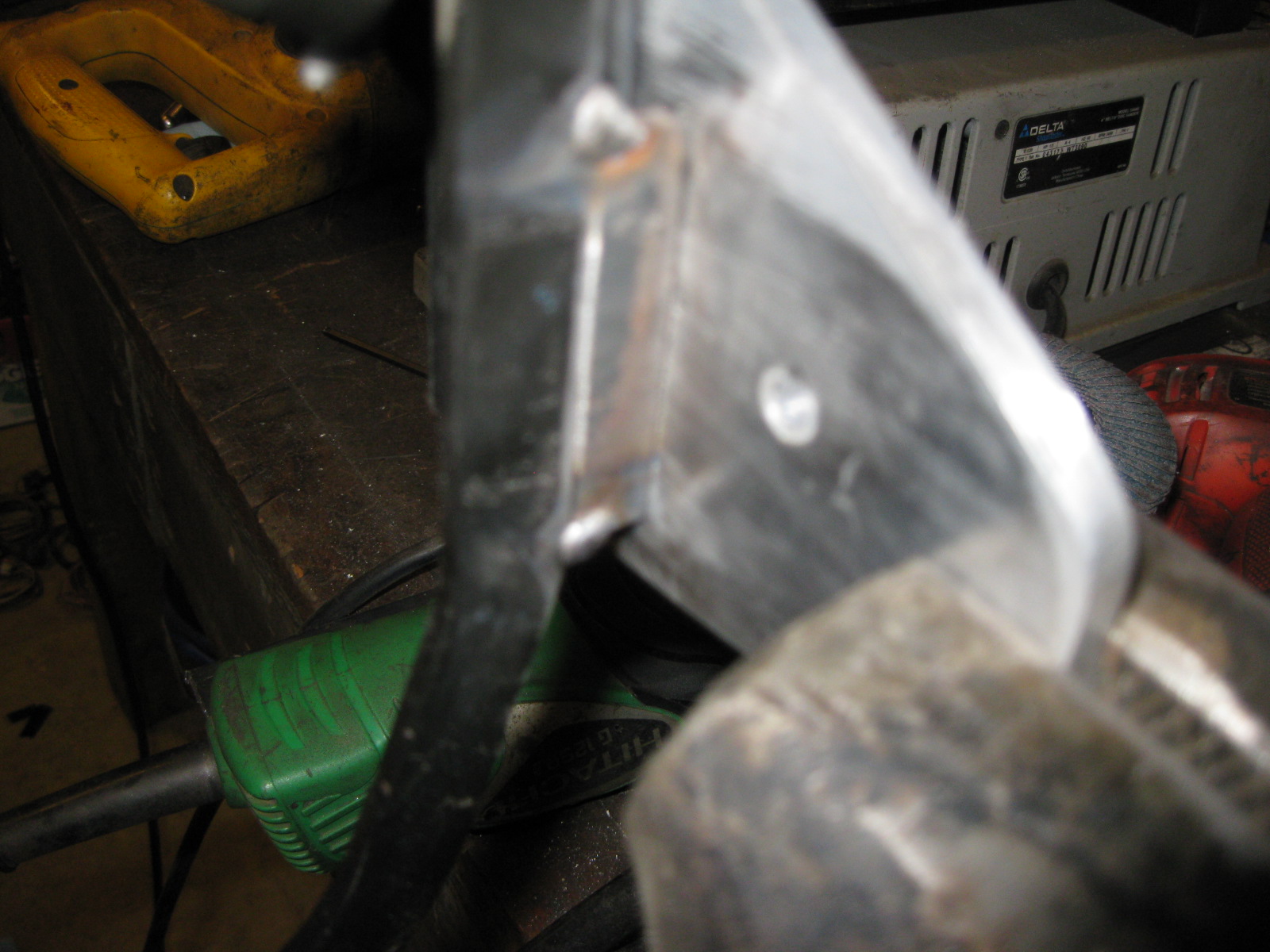
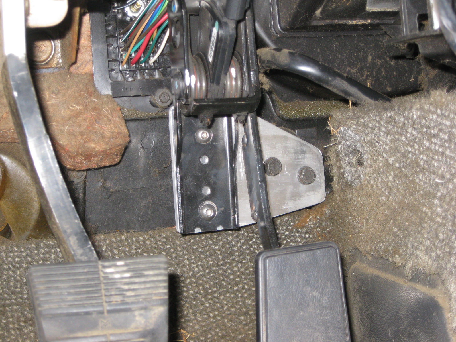
DBW throttle pedal is now installed. I fabbed up an aluminum bracket to mount the pedal to, then the aluminum bracket bolts to the stock fiero pedal mount. This allows the pedal to be slide to the drivers side enough to clear the brake booster vacuum tube. All I need to do for this was remove the plastic mounting block that comes with the throttle pedal (this block is also the primary throttle stop).
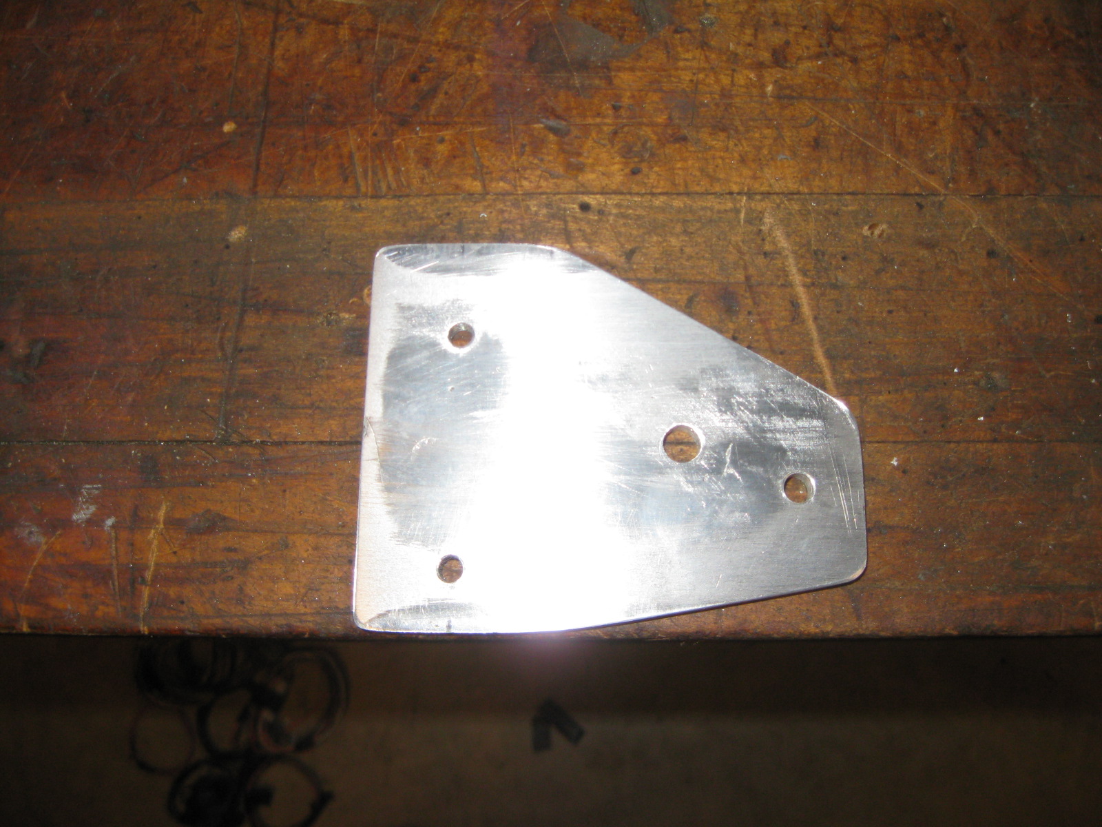
Since I removed the primary throttle stop, I welded on a new one. It is just some 3/16" steel the proper thickness welded to the backside of the throttle pedal arm so it will bottom out against the aluminum bracket.
Stock fiero throttle mounting bracket:
DBW pedal installed:
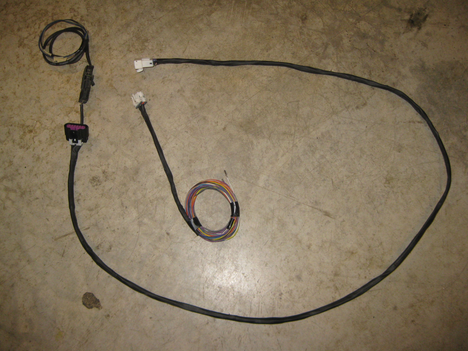
I also finished the interior jumper harness for the DBW pedal and Brake Booster sensor. It will has a 3 wire connector for the booster sensor right by the pedal assy. The other end has a 10 pin connector (3 wires for sensor, 6 wires for pedal).
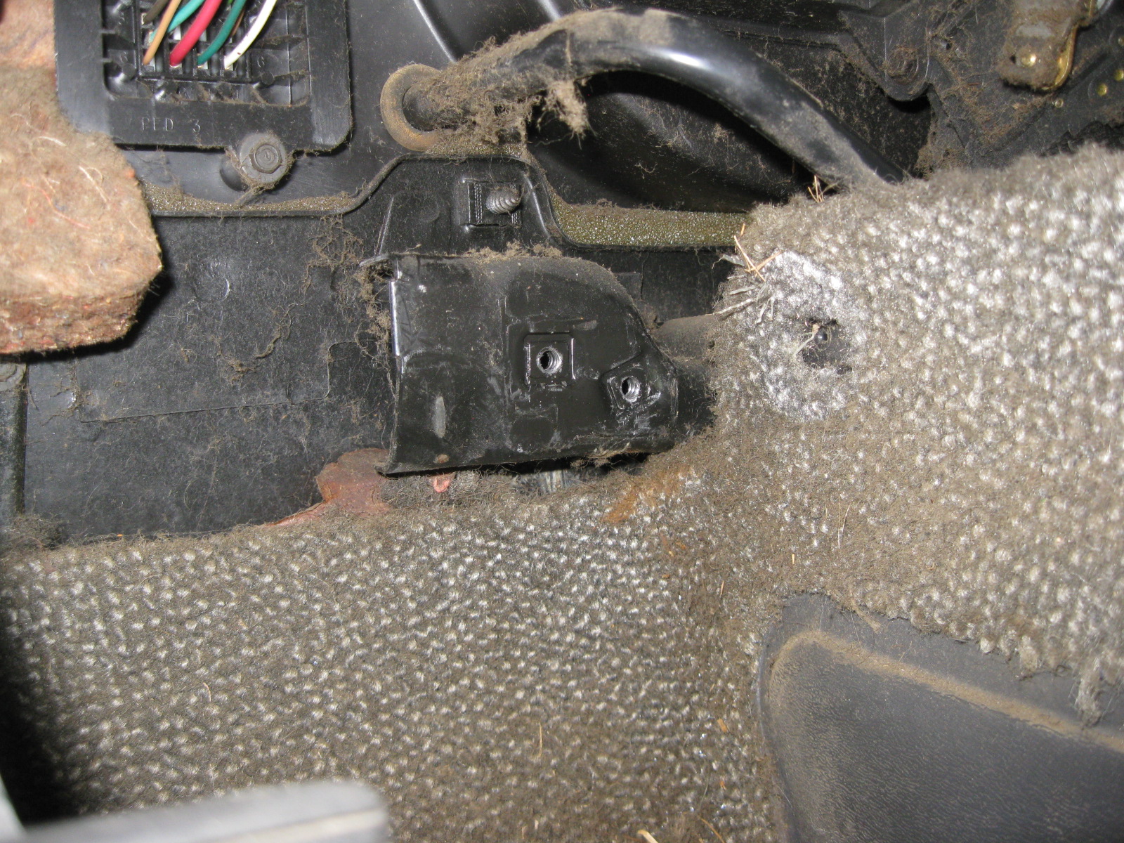
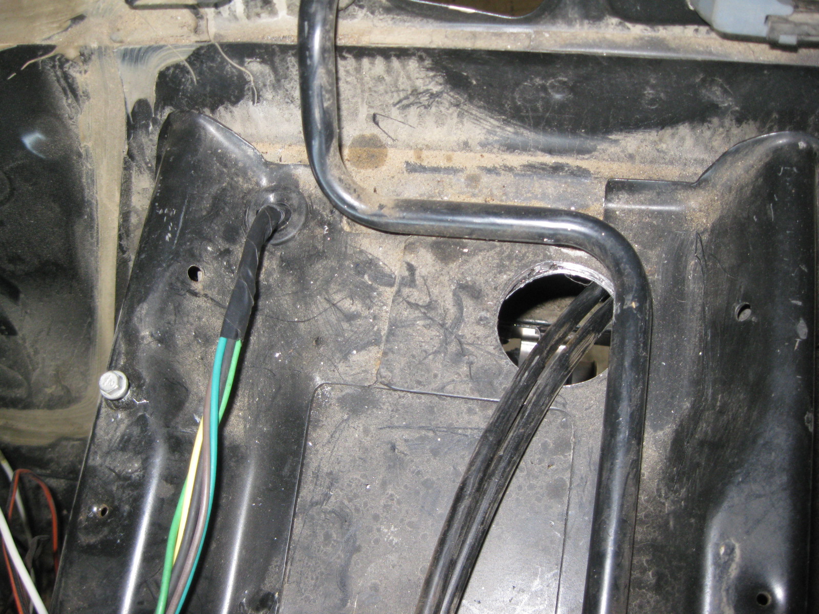
Drilled a hole in the plastic HVAC panel right by the C100 connector for the brake booster harness to pass through:
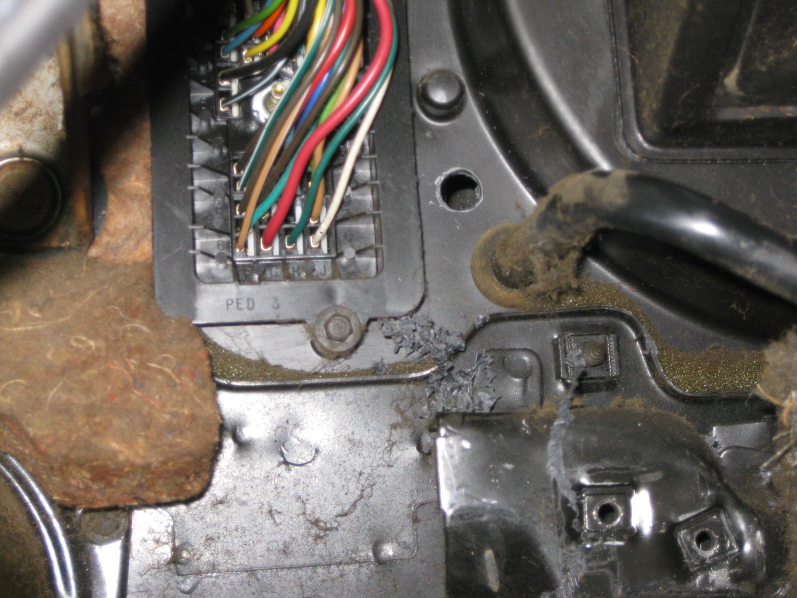
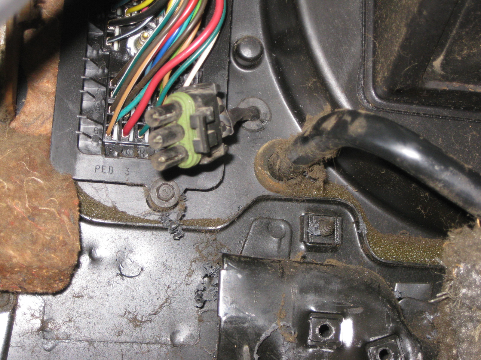
It is hard to see in this picture, but the harness comes through the firewall and goes under the C100 and under the brake booster to the other side:
Plenty of excess wire for when the sensor is installed in the booster. The raised flat circular surface will be drilled for the new sensor:
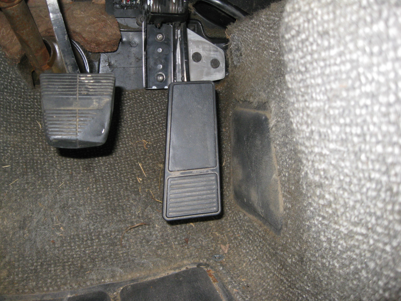
Back inside, the pedals were installed again and the jumper harness connected and routed through the center console area:
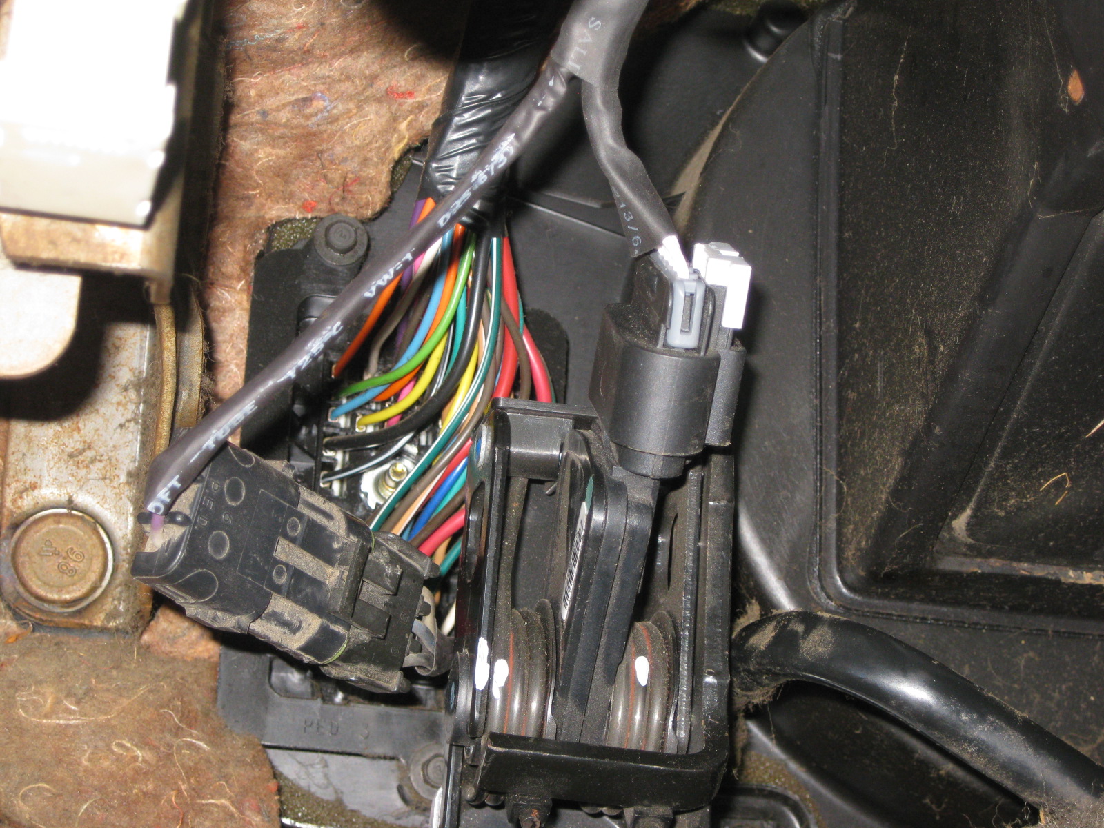
Also started working on the wiring for the TCM. All the needed resistors to mimic the solenoids and temp sensor as well as the 120 ohm terminator in the GMLAN line were all added in the body of the harness.
Still more wiring to be done...
Since I removed the primary throttle stop, I welded on a new one. It is just some 3/16" steel the proper thickness welded to the backside of the throttle pedal arm so it will bottom out against the aluminum bracket.
Stock fiero throttle mounting bracket:
DBW pedal installed:
I also finished the interior jumper harness for the DBW pedal and Brake Booster sensor. It will has a 3 wire connector for the booster sensor right by the pedal assy. The other end has a 10 pin connector (3 wires for sensor, 6 wires for pedal).
Drilled a hole in the plastic HVAC panel right by the C100 connector for the brake booster harness to pass through:
It is hard to see in this picture, but the harness comes through the firewall and goes under the C100 and under the brake booster to the other side:
Plenty of excess wire for when the sensor is installed in the booster. The raised flat circular surface will be drilled for the new sensor:
Back inside, the pedals were installed again and the jumper harness connected and routed through the center console area:
Also started working on the wiring for the TCM. All the needed resistors to mimic the solenoids and temp sensor as well as the 120 ohm terminator in the GMLAN line were all added in the body of the harness.
Still more wiring to be done...
11-10-2012, 06:05 PM
#58
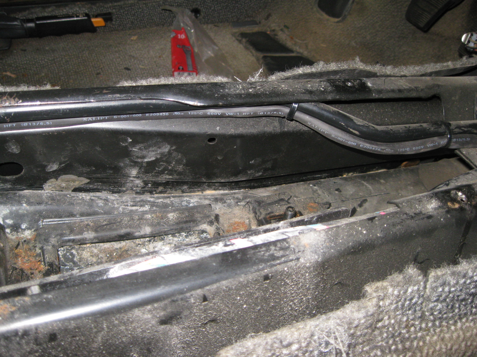
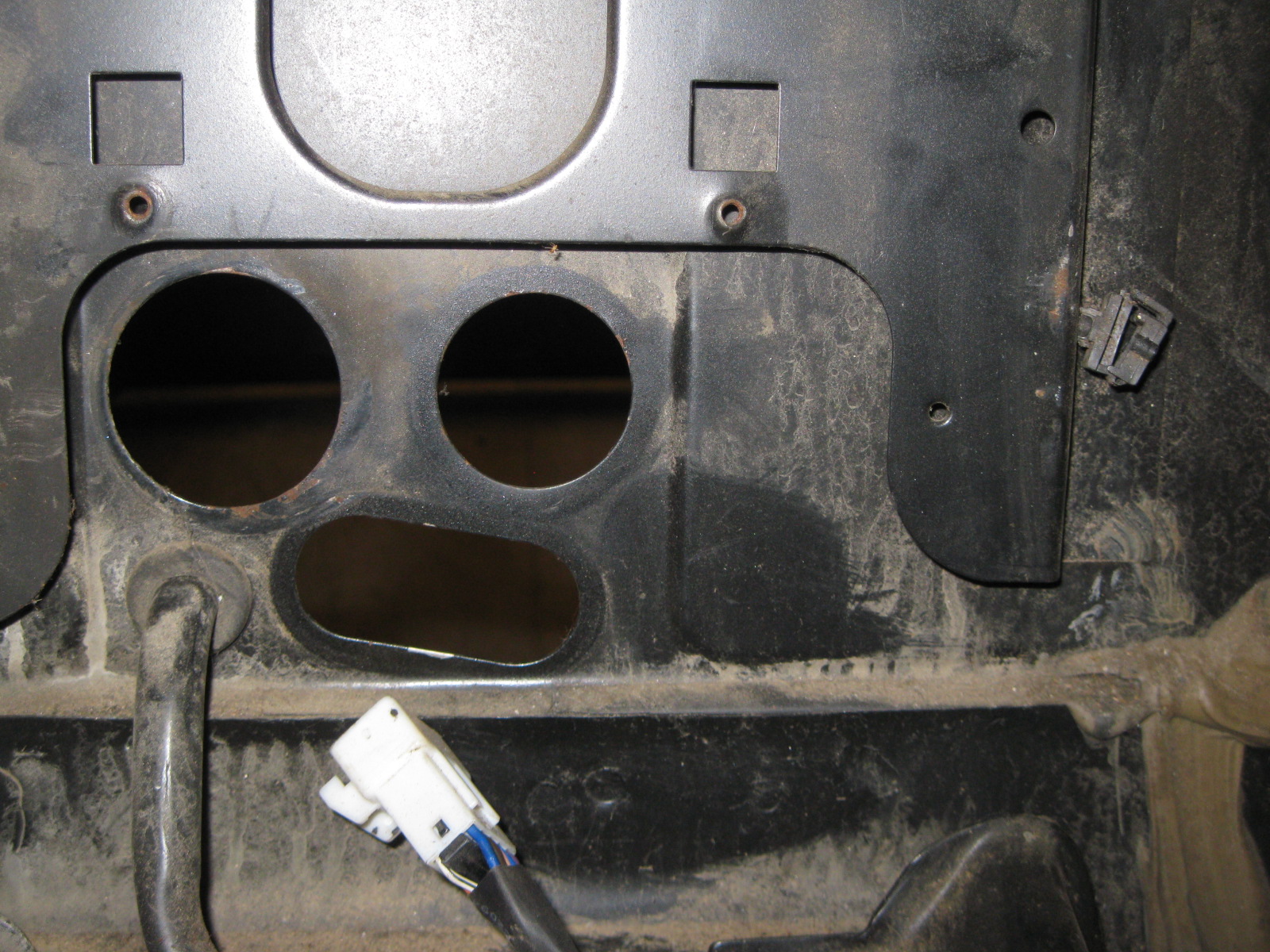
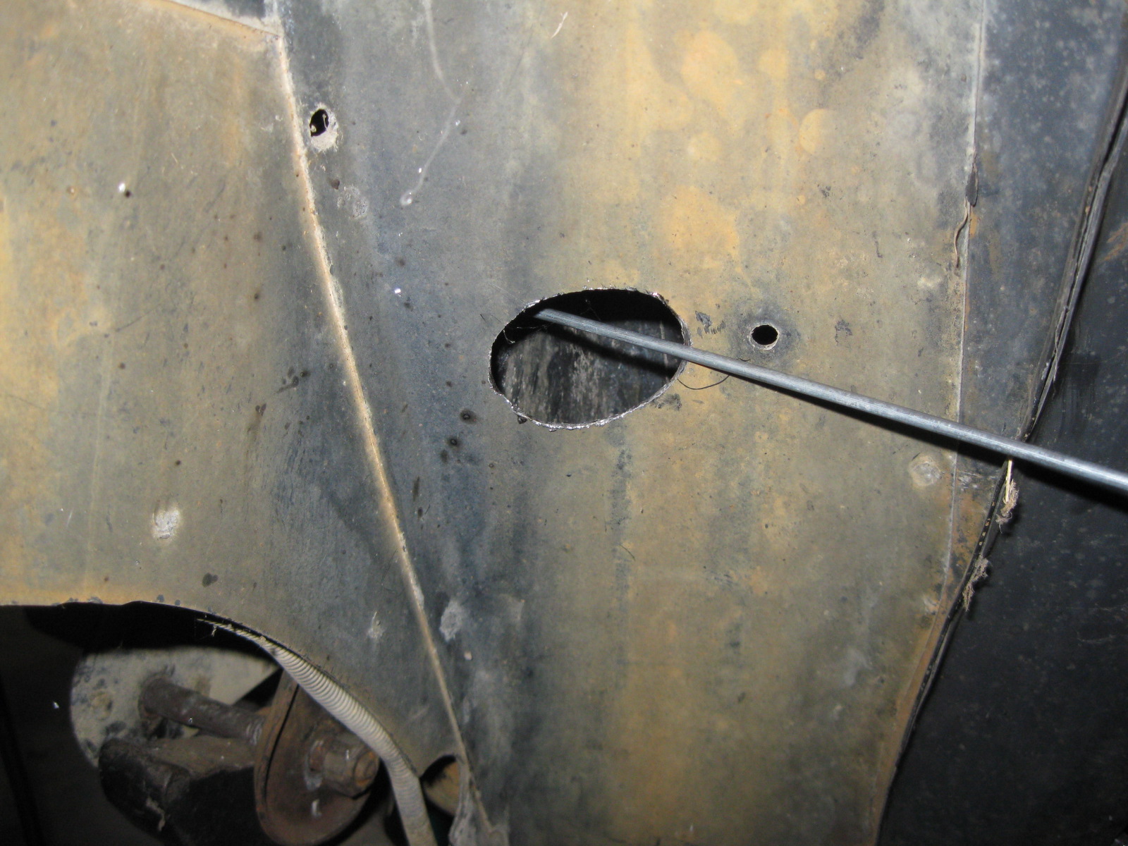
Spent most of last weekend prepping the chassis wiring... relocating the pass through firewall connector and eliminating the 500 connector.
Here is the stock firewall where the single pass through connector will go:
My drill guide to round the corners of the cutout:
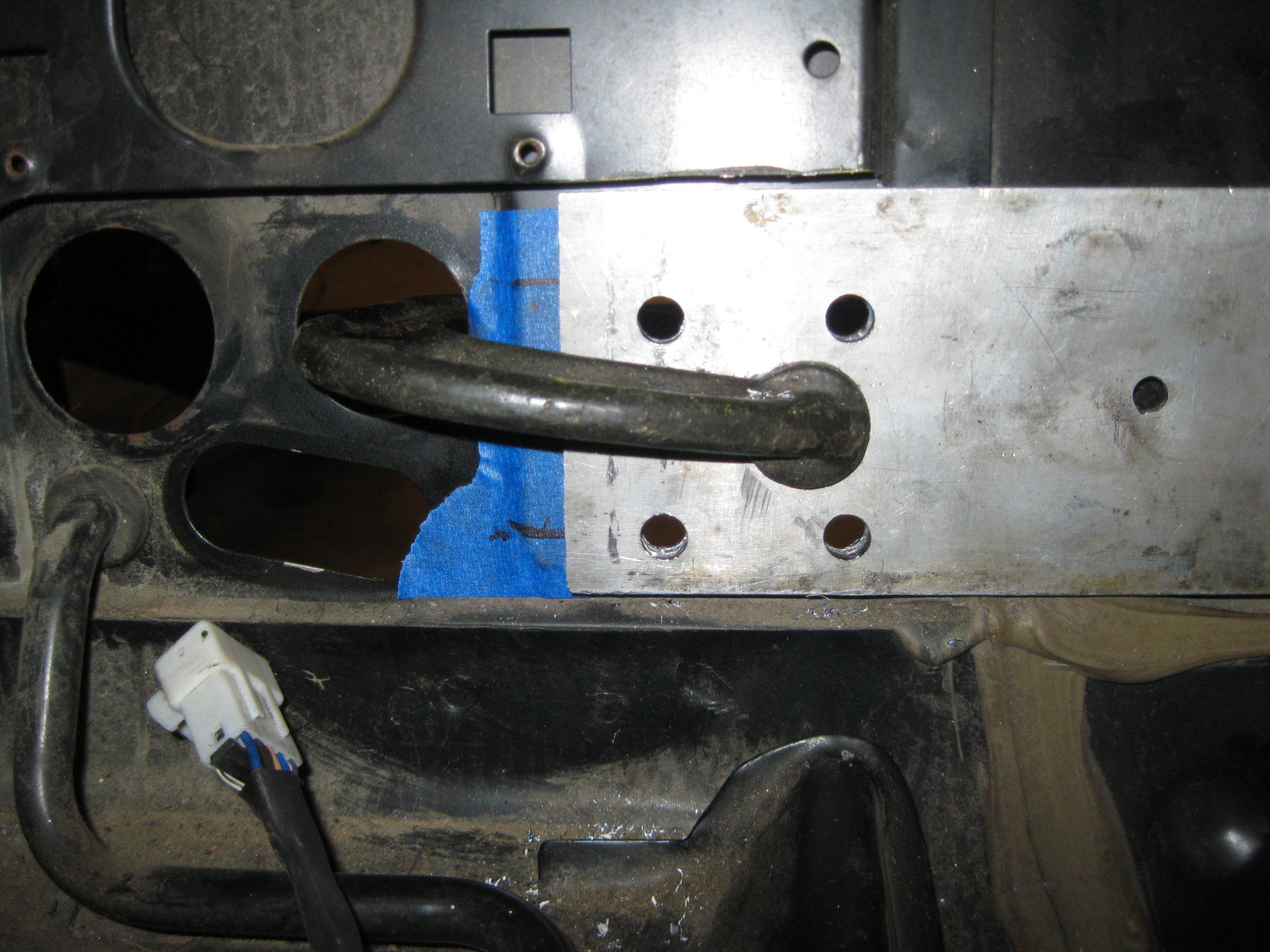
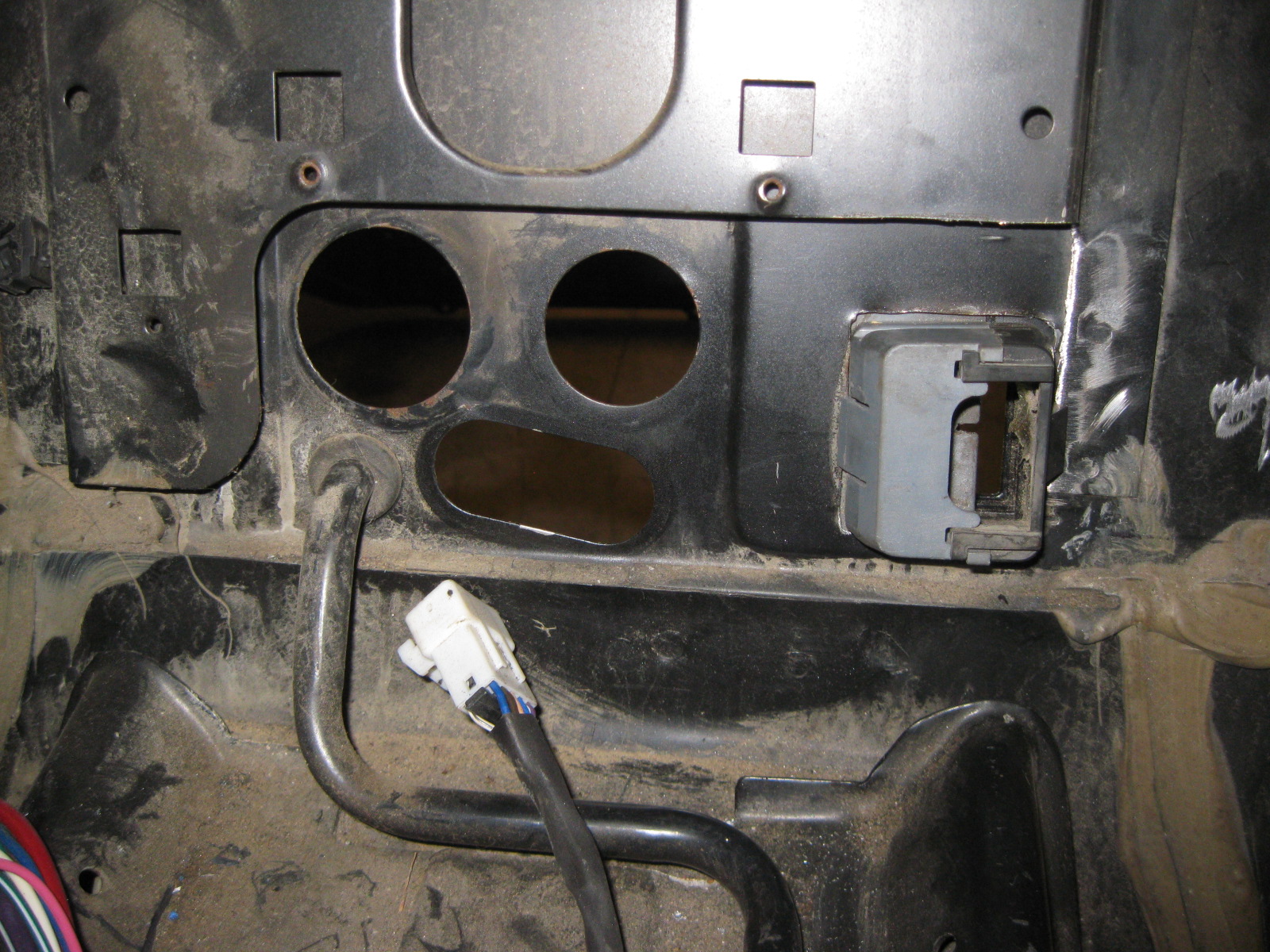
Connector in its new home:
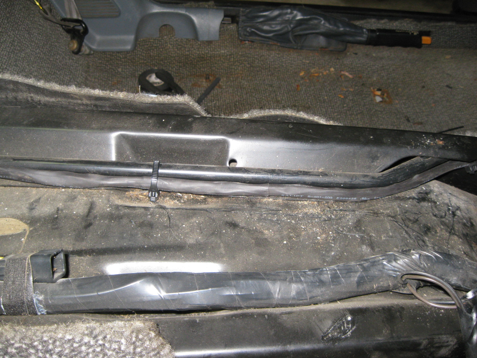
Then it was time to work on the 500 harness and prep it for removing the actual 500 connector:
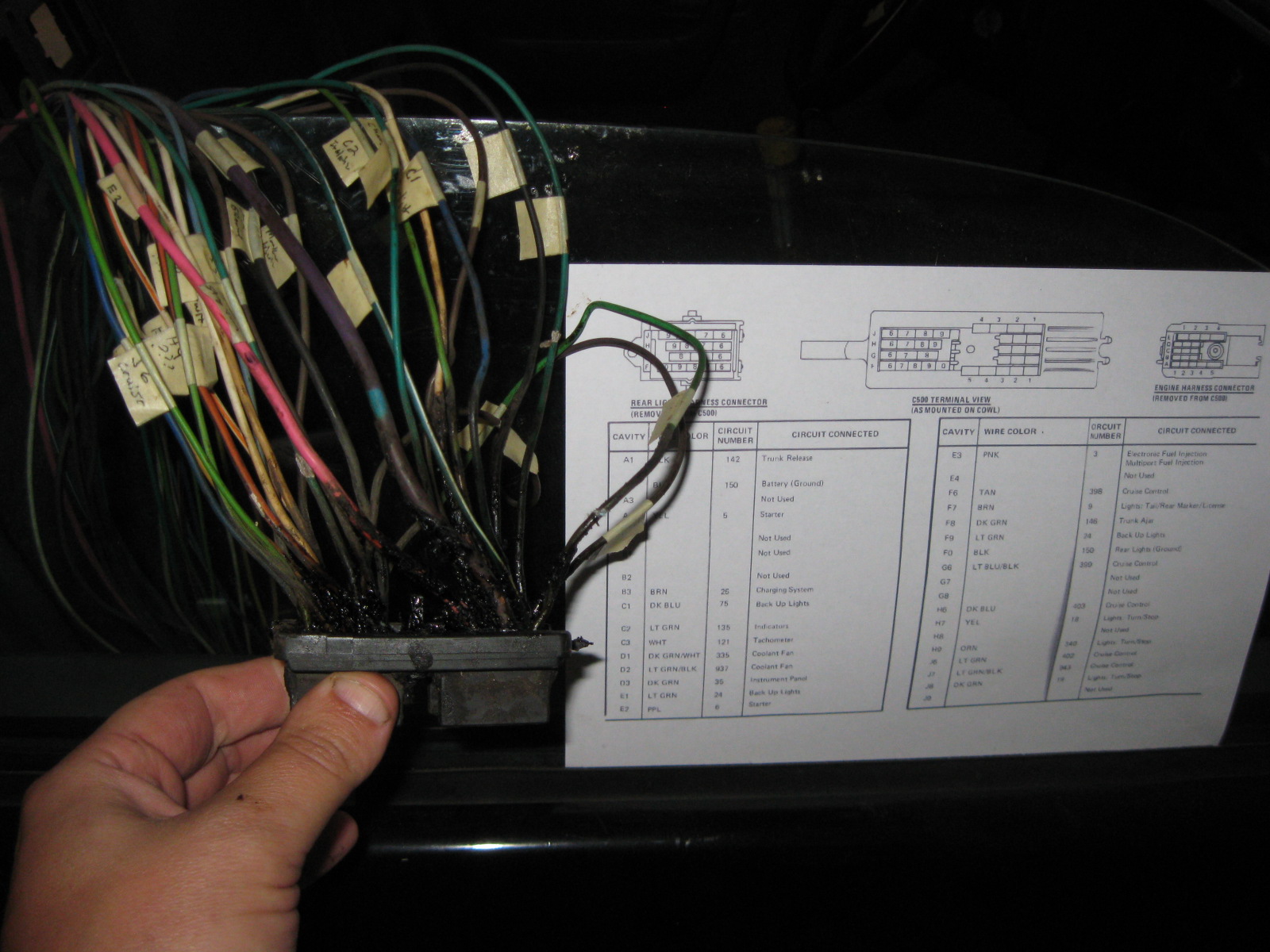
Once the connector was gone, I separated the wires from engine side to tail light side:
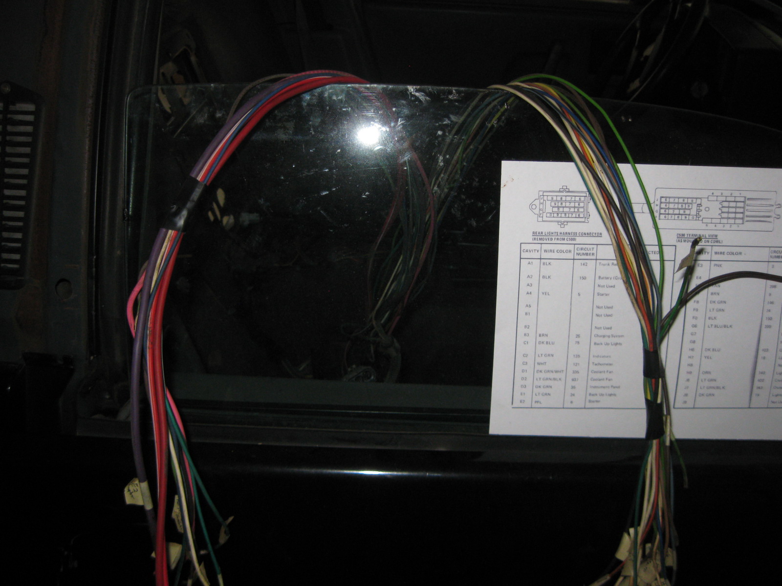
The bulkhead connector on this harness needed to be removed, so boiled some water in a pot and then set it in the car (on a rotor). Soaking the connector for about 5 minutes in hot water softens the glue to the point that is is fairly easy to disassemble the connector:
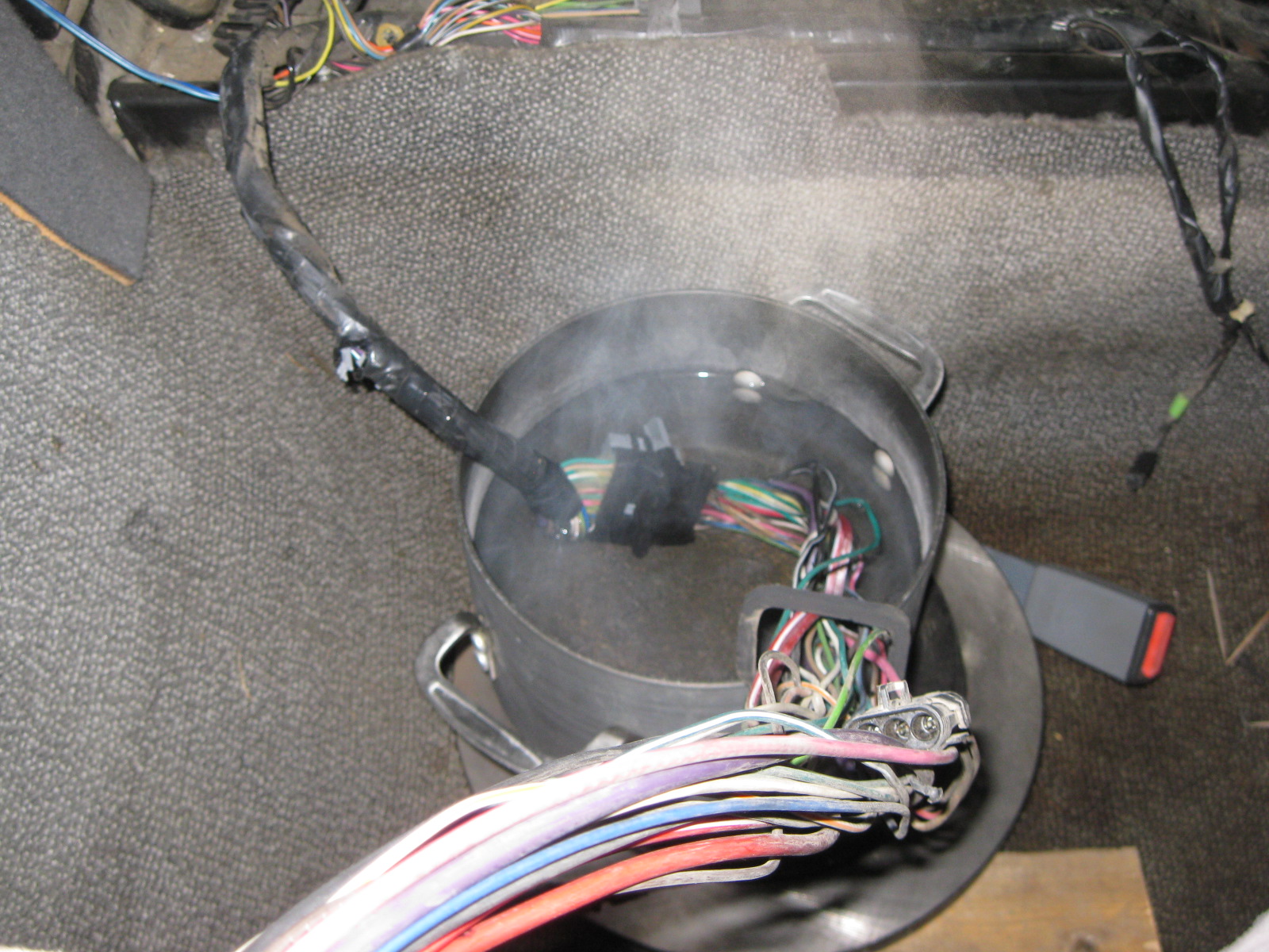
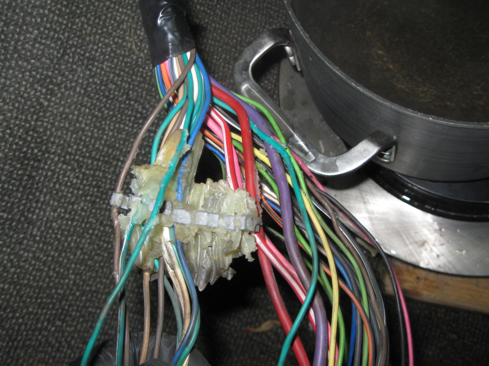
Did the same to the tail light harness 500 connector:
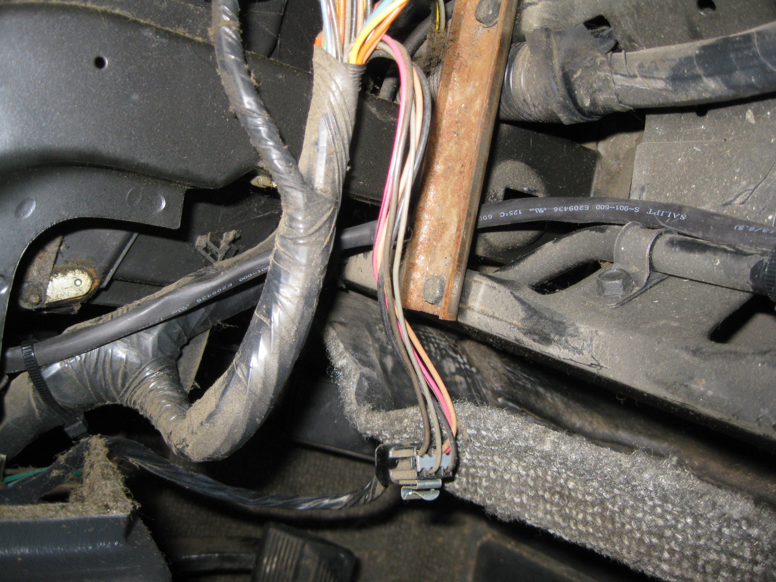
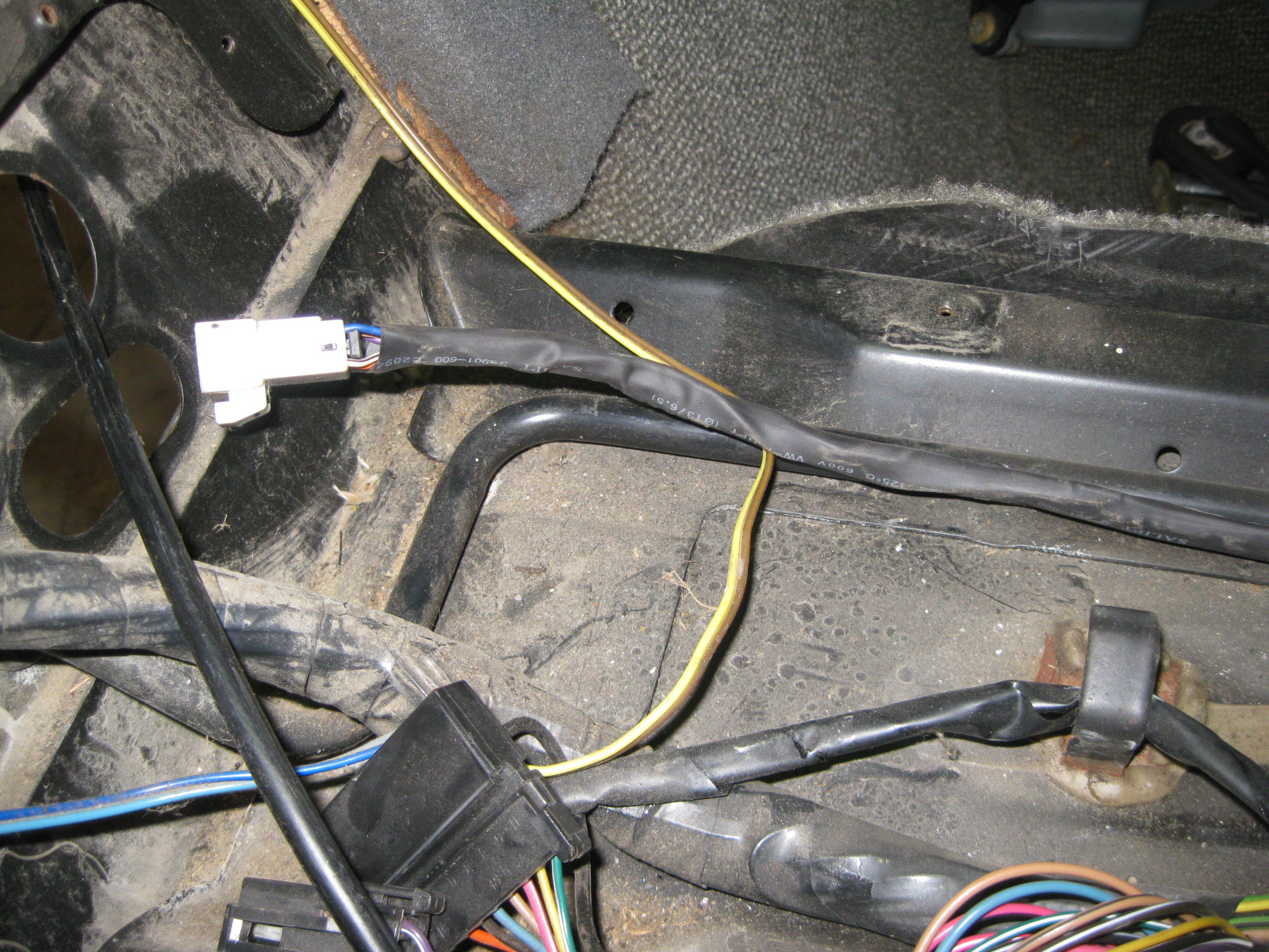
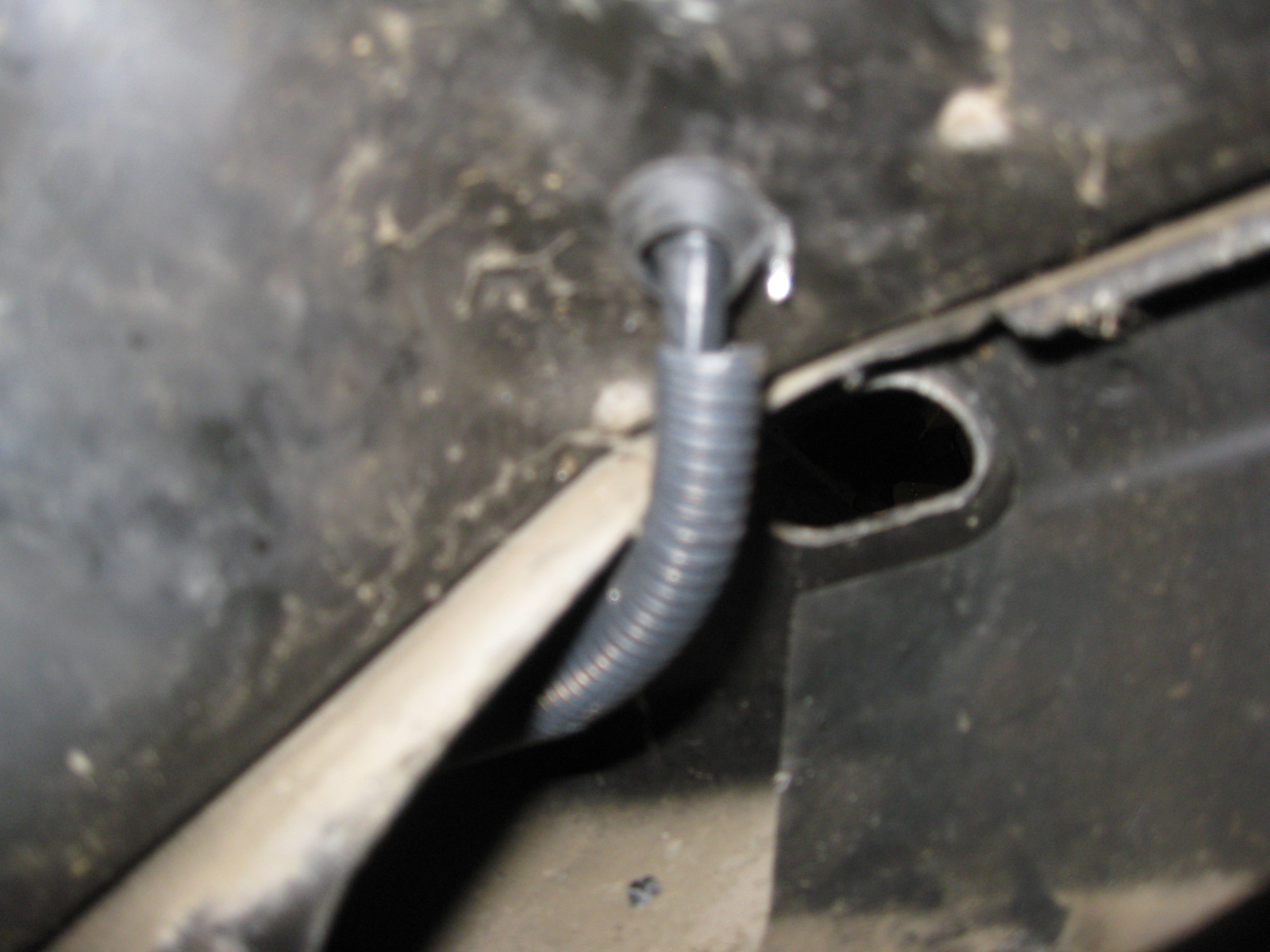
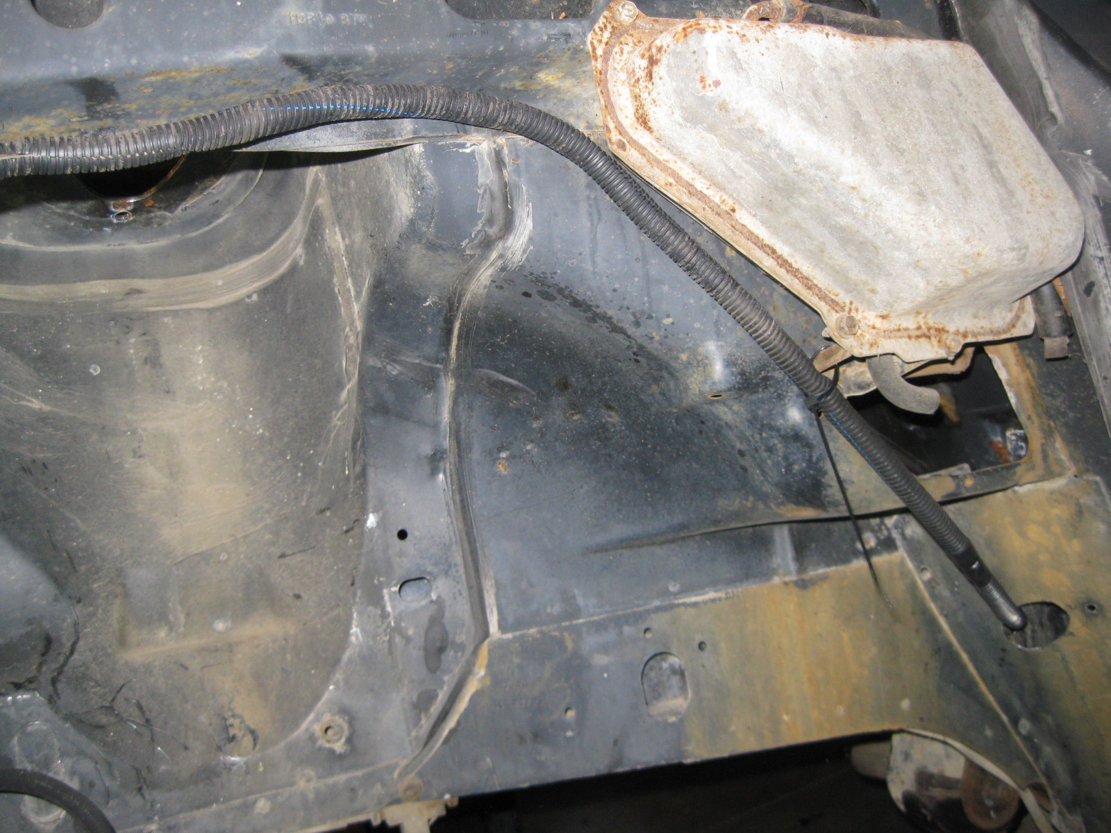
Using a hole saw, I cut through 2 sections of steel below the B-pillar area which gave me access to the double firewall section. I fished a piece of steel rod through there and taped the tail light harness to it. Also drilled a 5/8" hole in the console area to pass the wires into the fuel tank/double firewall section. Tape the wires to the steel rod and pull it back out:
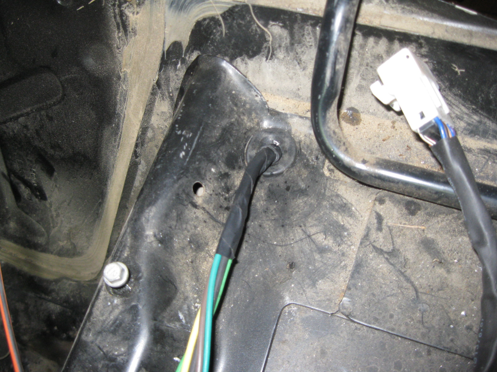
Underside of fuel tank/double firewall area:
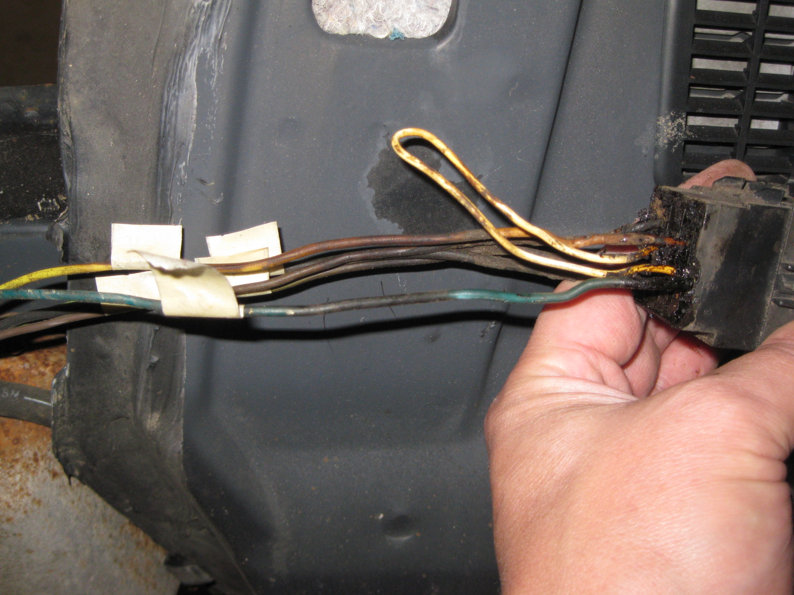
The the tail light harness wires were cut to the proper length and splices, soldered, shrink wrapped and loomed:
Here is the stock firewall where the single pass through connector will go:
My drill guide to round the corners of the cutout:
Connector in its new home:
Then it was time to work on the 500 harness and prep it for removing the actual 500 connector:
Once the connector was gone, I separated the wires from engine side to tail light side:
The bulkhead connector on this harness needed to be removed, so boiled some water in a pot and then set it in the car (on a rotor). Soaking the connector for about 5 minutes in hot water softens the glue to the point that is is fairly easy to disassemble the connector:
Did the same to the tail light harness 500 connector:
Using a hole saw, I cut through 2 sections of steel below the B-pillar area which gave me access to the double firewall section. I fished a piece of steel rod through there and taped the tail light harness to it. Also drilled a 5/8" hole in the console area to pass the wires into the fuel tank/double firewall section. Tape the wires to the steel rod and pull it back out:
Underside of fuel tank/double firewall area:
The the tail light harness wires were cut to the proper length and splices, soldered, shrink wrapped and loomed:
11-10-2012, 06:07 PM
#59
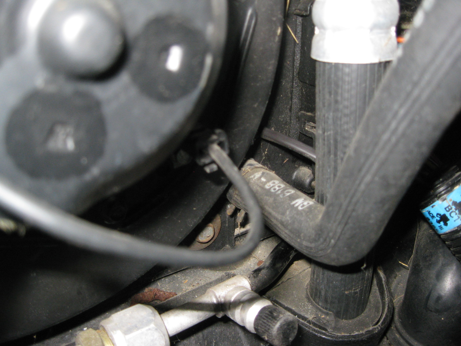
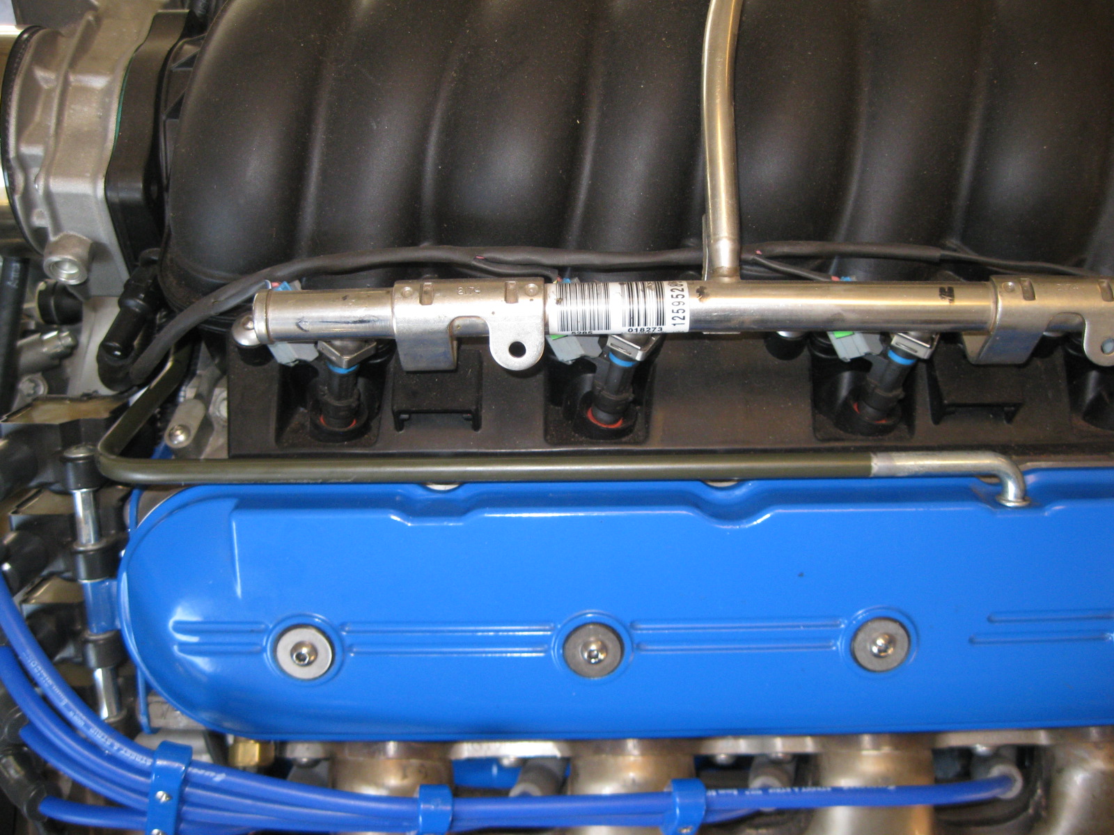
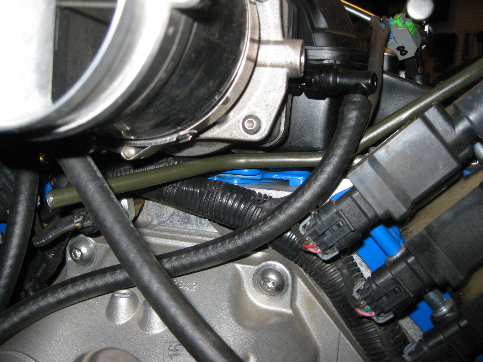
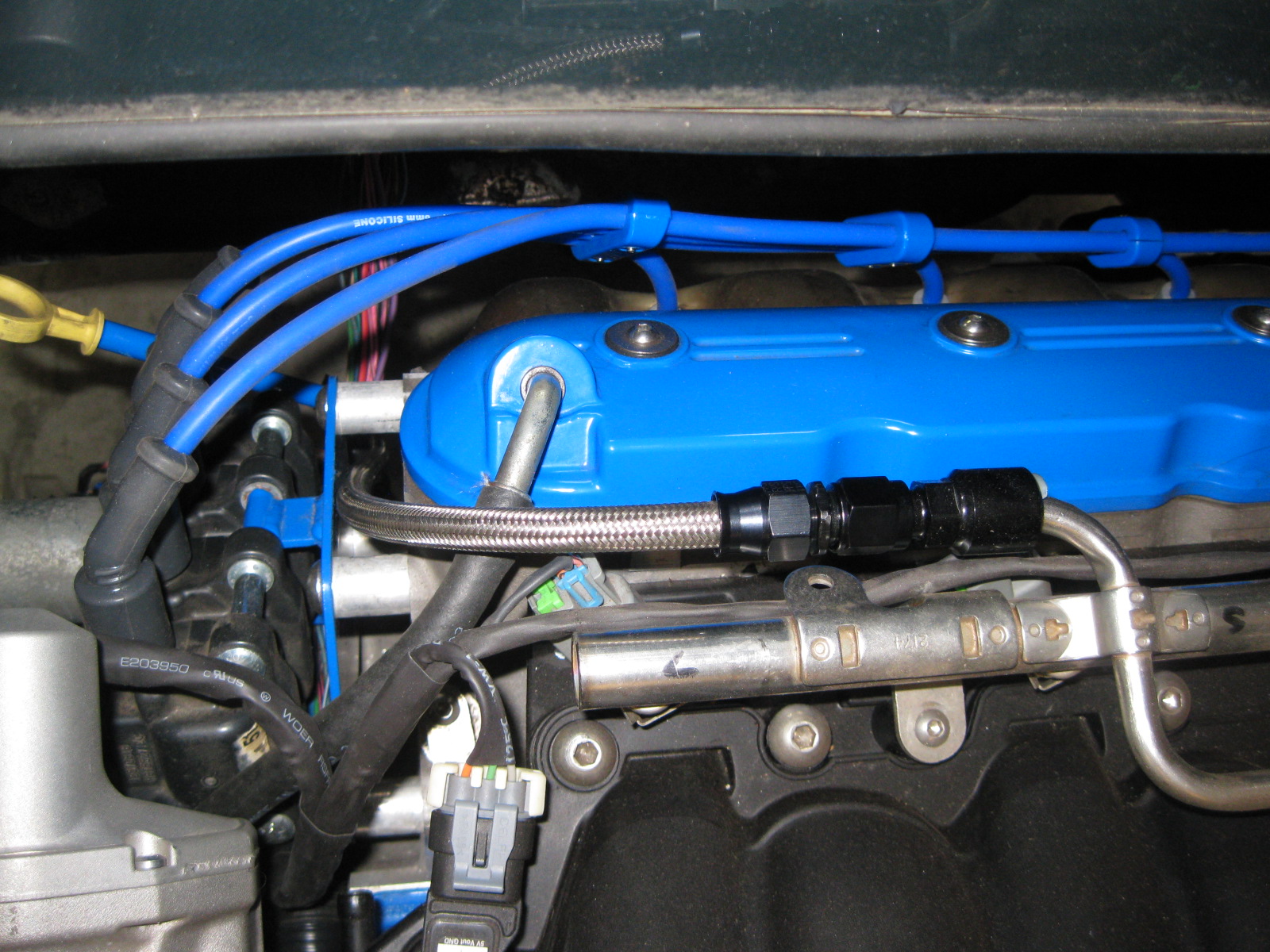
I wasn't feeling the rubber PCV hose going from the throttle body/maf coupler to the rear valve cover. Too bulky and not straight/parallel with the valve cover:
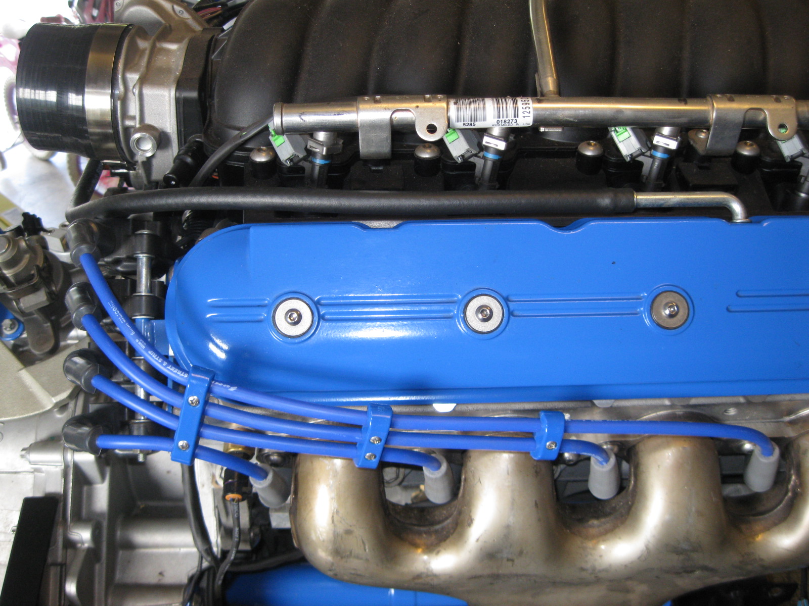
So I decided to redo it with 3/8" hard steel line. Once it was went into the proper shape, I cut the barb portion off the valve cover end, fabbed up a 5/16" internal tube splice, then silver soldered the valve cover side, and JB welded the other side. I didn't silver solder the other side due to the paint/primer on the tube and I wanted it to have as little movement as possible while setting up.
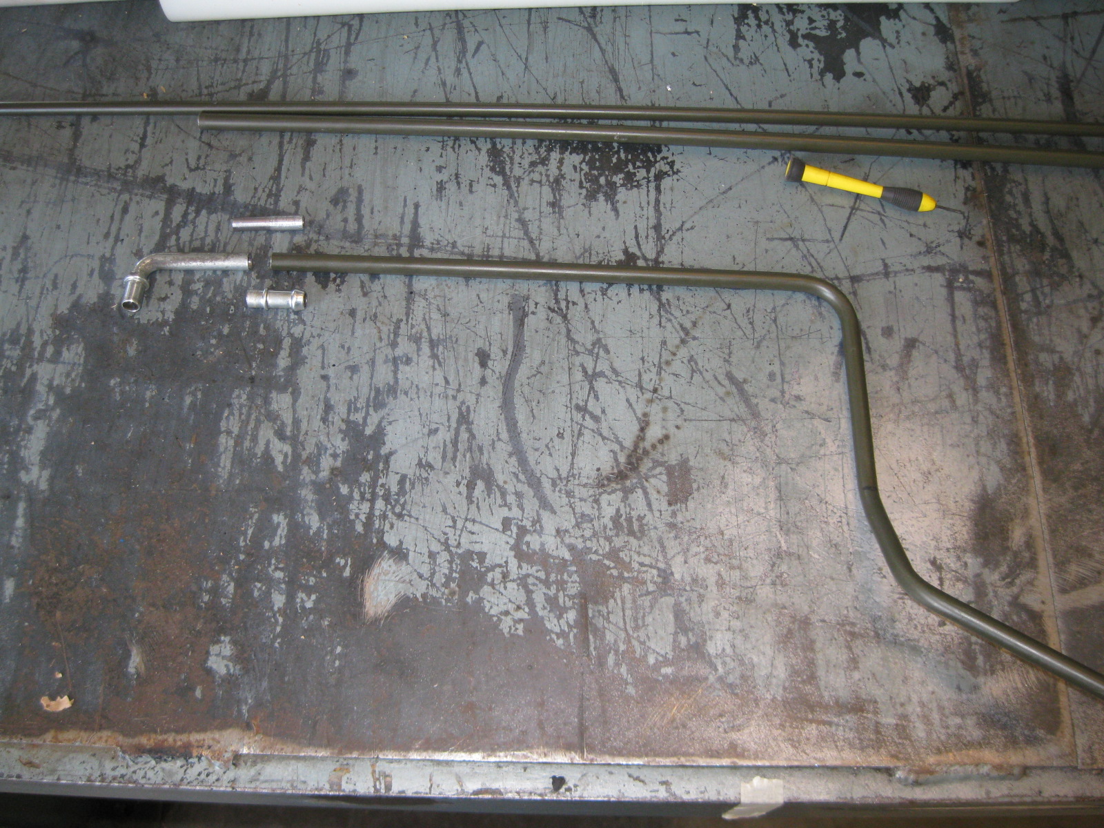
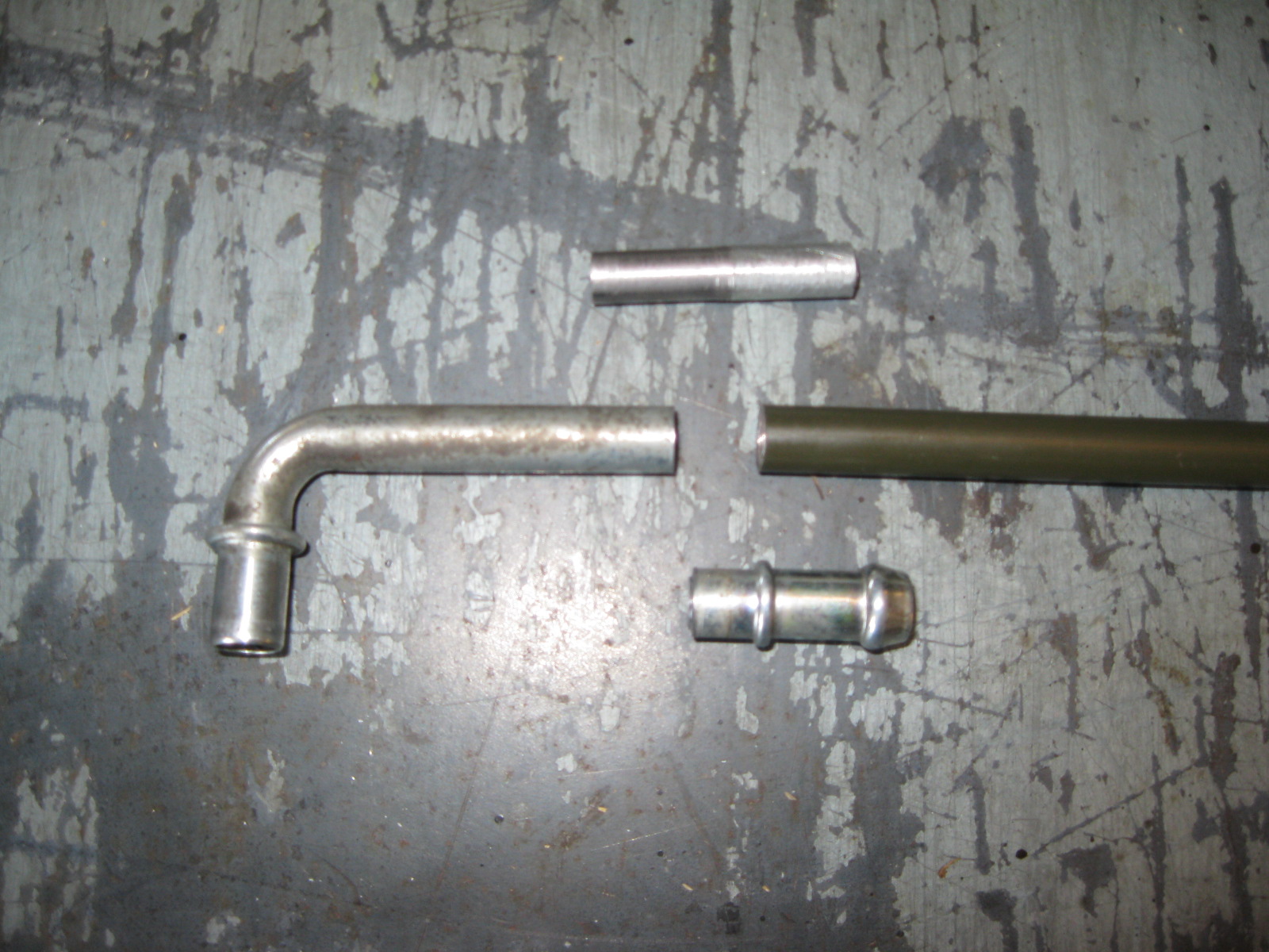
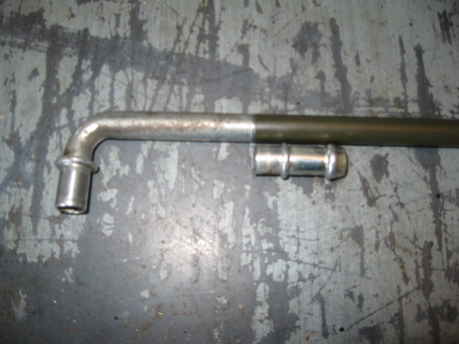
I am much happier with this setup. Once the tube is painted semi-gloss black it will fade away into the intake manifold. I still need to trim the end at the throttle body and run a short section of hose to connect it.
So I decided to redo it with 3/8" hard steel line. Once it was went into the proper shape, I cut the barb portion off the valve cover end, fabbed up a 5/16" internal tube splice, then silver soldered the valve cover side, and JB welded the other side. I didn't silver solder the other side due to the paint/primer on the tube and I wanted it to have as little movement as possible while setting up.
I am much happier with this setup. Once the tube is painted semi-gloss black it will fade away into the intake manifold. I still need to trim the end at the throttle body and run a short section of hose to connect it.
11-11-2012, 03:17 PM
#60
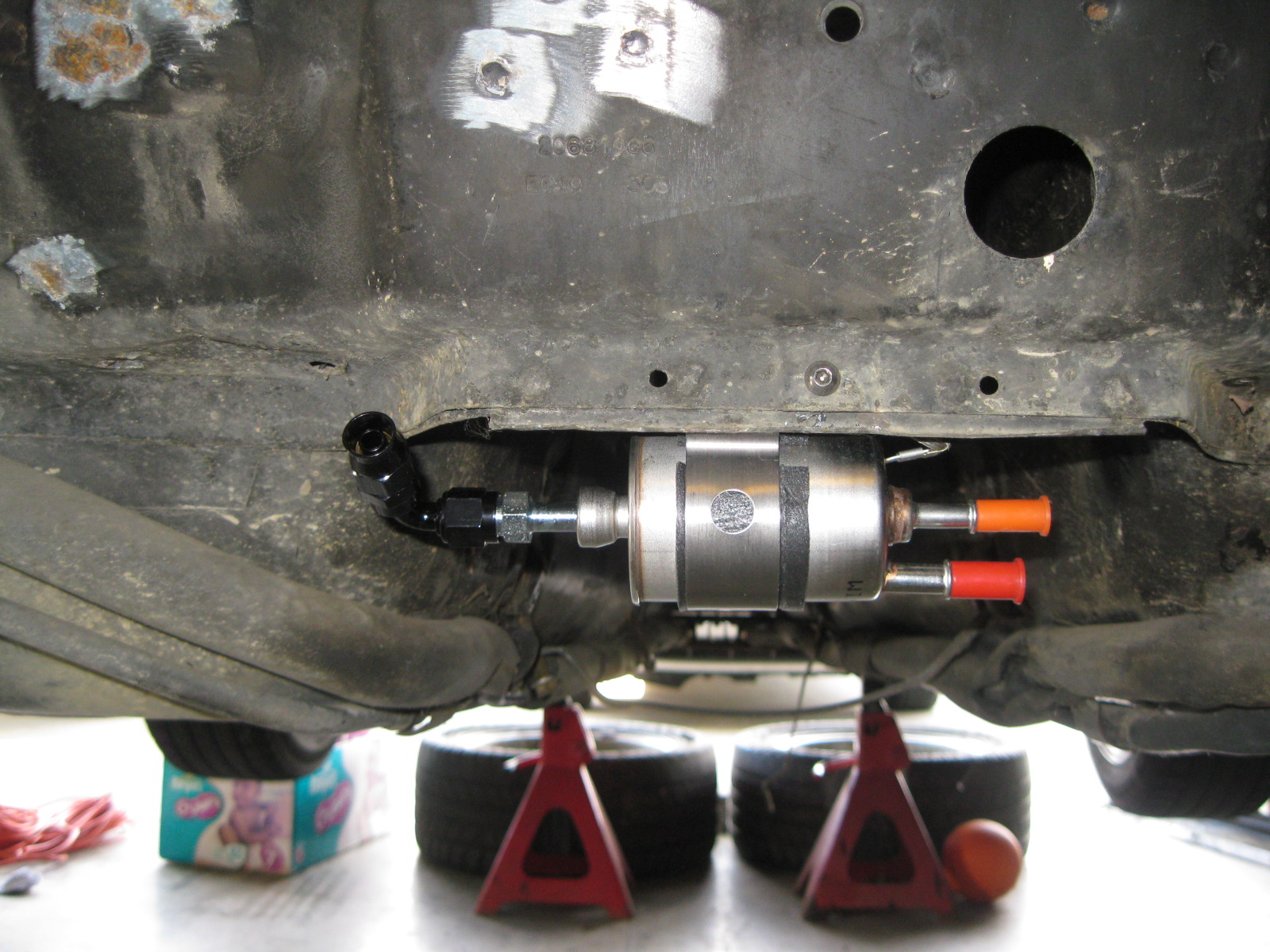
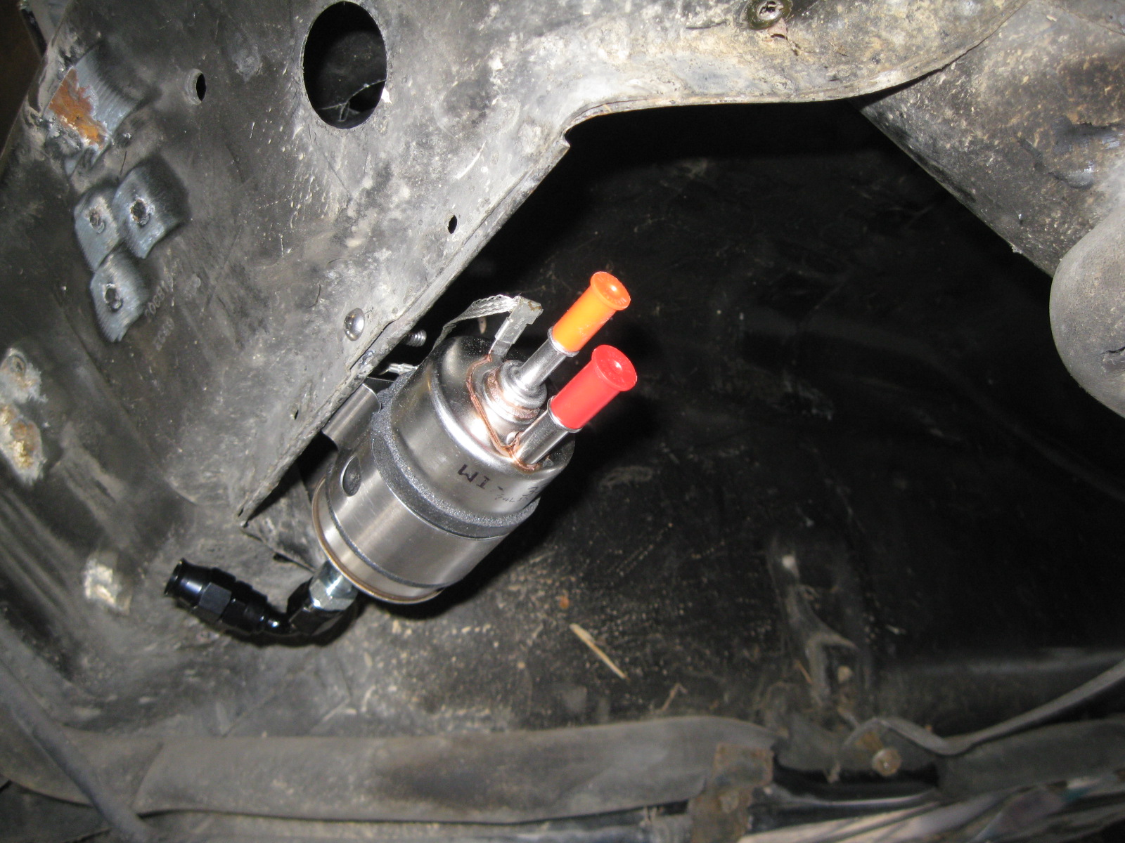
Mounted the fuel filter (I slid the bracket that comes with it off and flipped it around):
Took apart the G6 clutch master/bleeder assy and modified it to take a traditional flared line. Machined both pieces for a press fit then silver soldered them together:
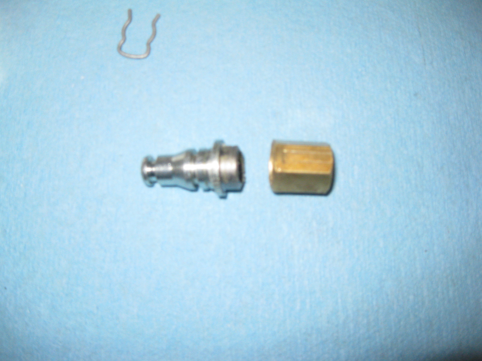
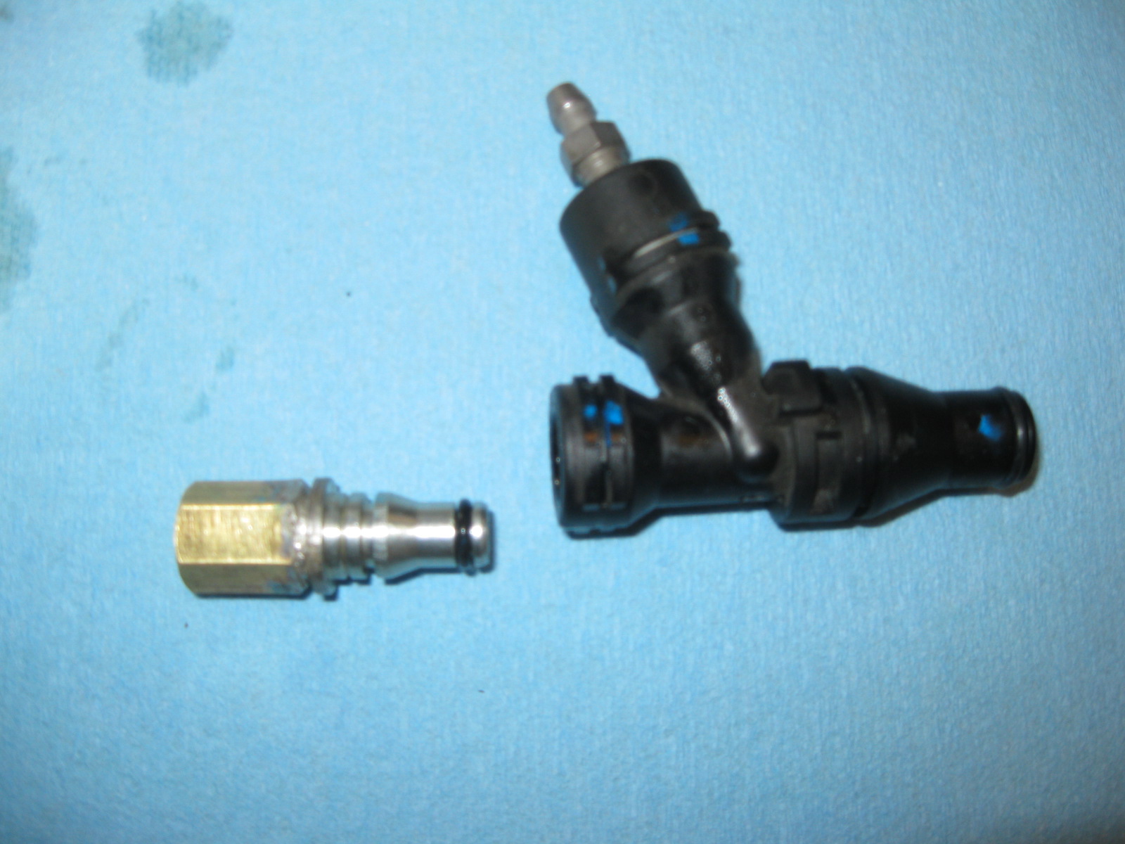
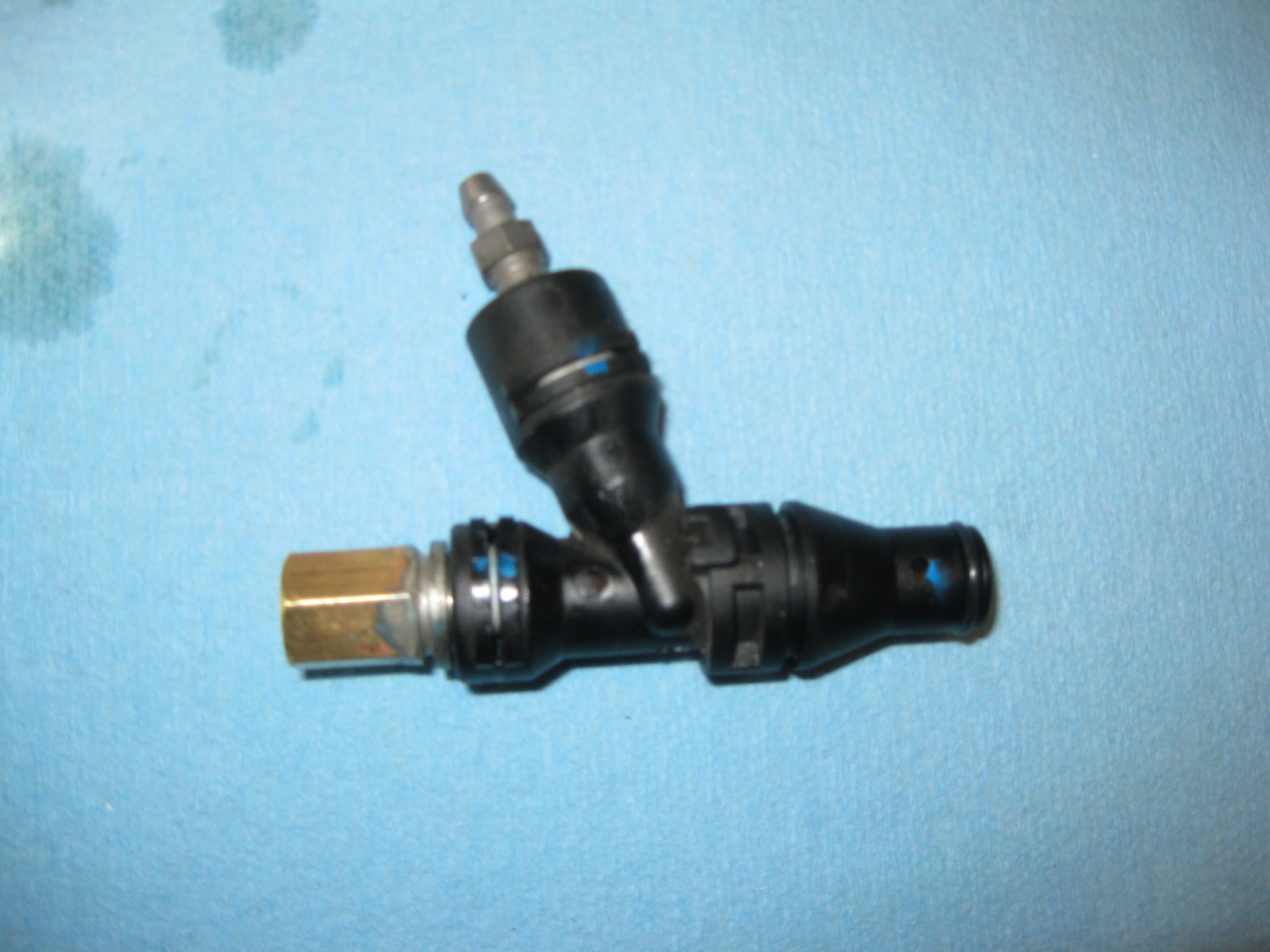
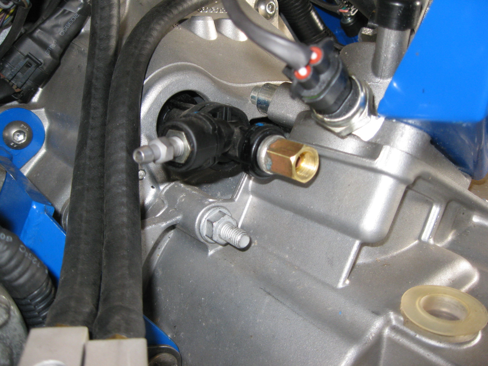
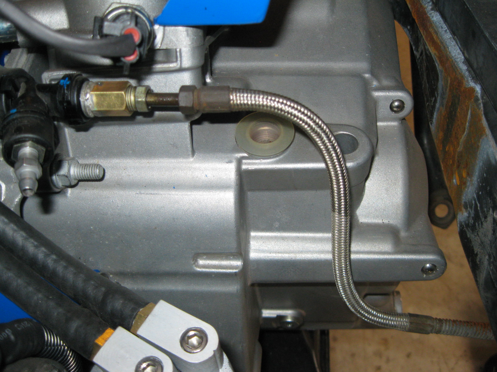
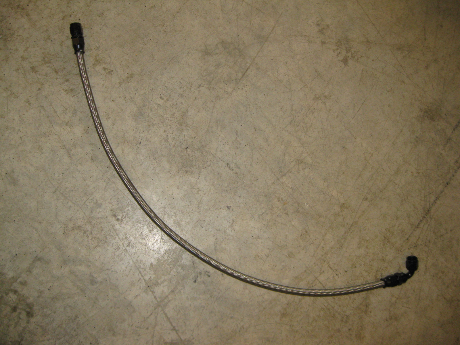
Since the engine was put back in place for the wiring, I also took the opportunity to make the fuel hose:
I wanted to keep the shifter cables as far from heat as possible, so I routed them down into the double firewall section and out by the fuel fill tubes. I will probably remove the insulation on them.
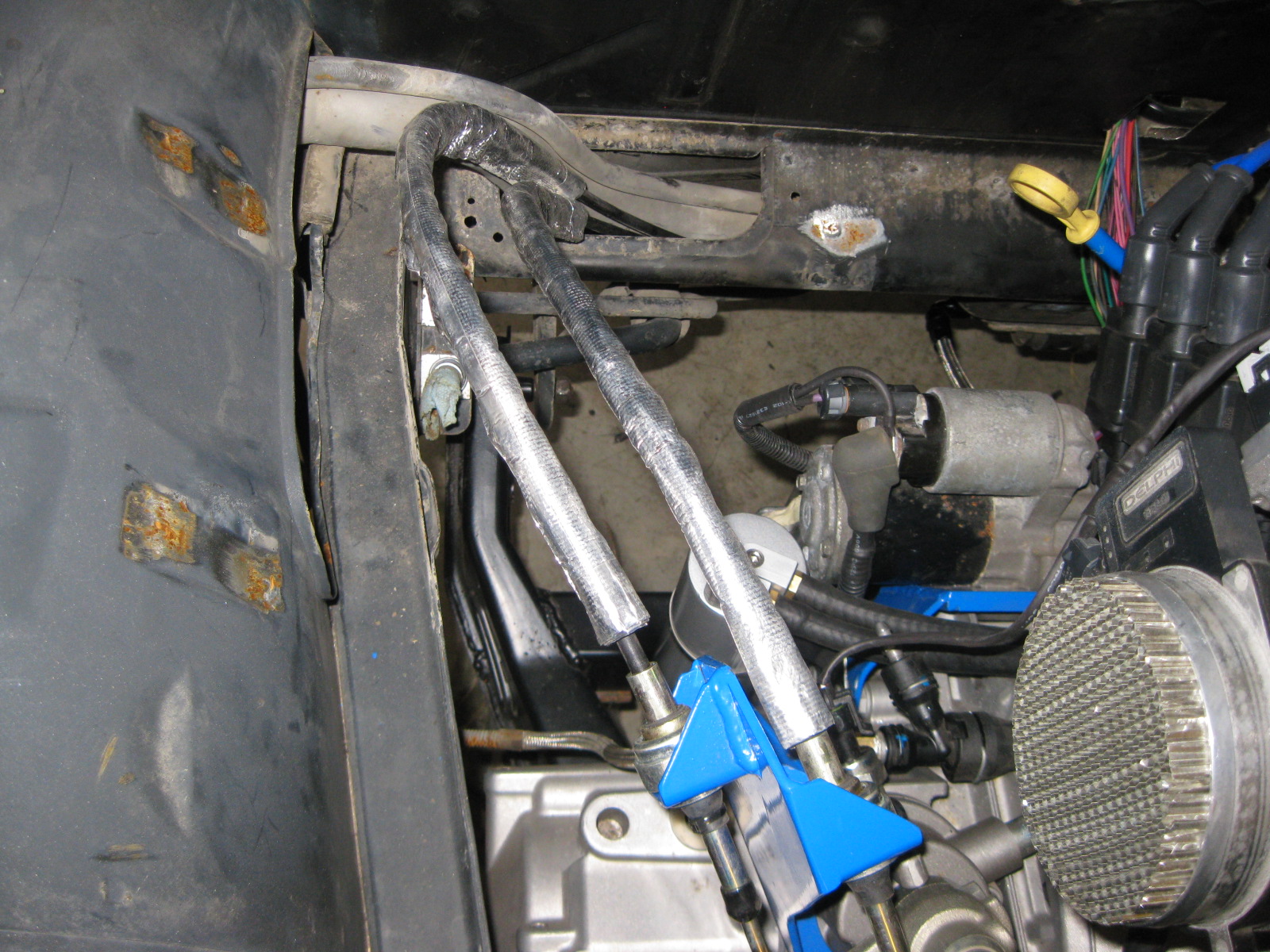
Here are some overall pics:
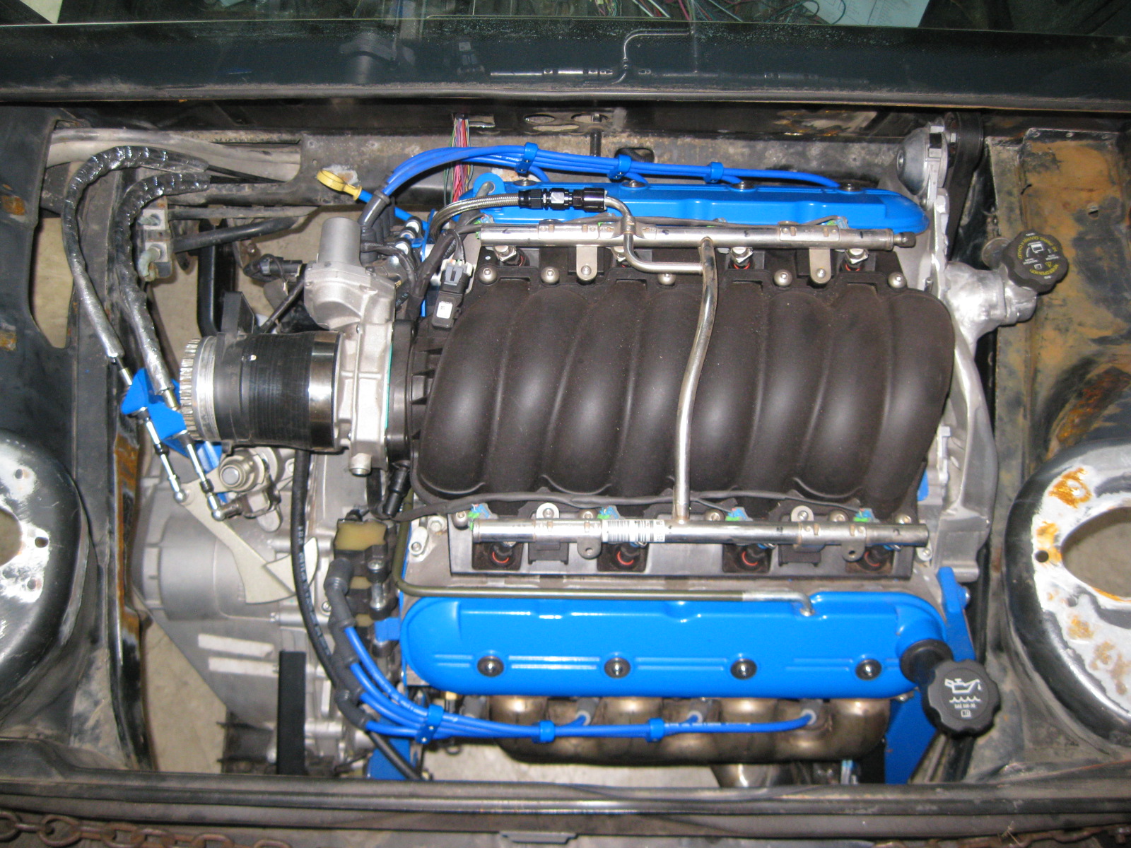
While the engine is in place, I need to finish the wiring harness, coolant connections, A/C hoses and fabricate a cold air intake (the GM truck one doesn't quite fit and I don't want to cut it up and have more couplers, I will get some exhaust tubing and weld something up). Then it will come back out to finish all the detail work in the engine bay.
Took apart the G6 clutch master/bleeder assy and modified it to take a traditional flared line. Machined both pieces for a press fit then silver soldered them together:
Since the engine was put back in place for the wiring, I also took the opportunity to make the fuel hose:
I wanted to keep the shifter cables as far from heat as possible, so I routed them down into the double firewall section and out by the fuel fill tubes. I will probably remove the insulation on them.
Here are some overall pics:
While the engine is in place, I need to finish the wiring harness, coolant connections, A/C hoses and fabricate a cold air intake (the GM truck one doesn't quite fit and I don't want to cut it up and have more couplers, I will get some exhaust tubing and weld something up). Then it will come back out to finish all the detail work in the engine bay.