

My First BMW – My First Swap – LS2/T56 into an E36


 04-16-2014 | 05:35 PM
#24
Ordered the engine mount kit from JTR today.
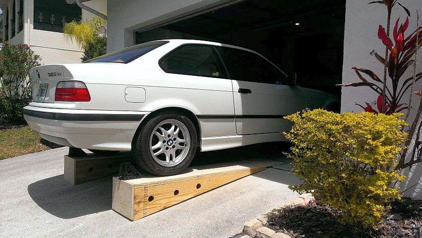
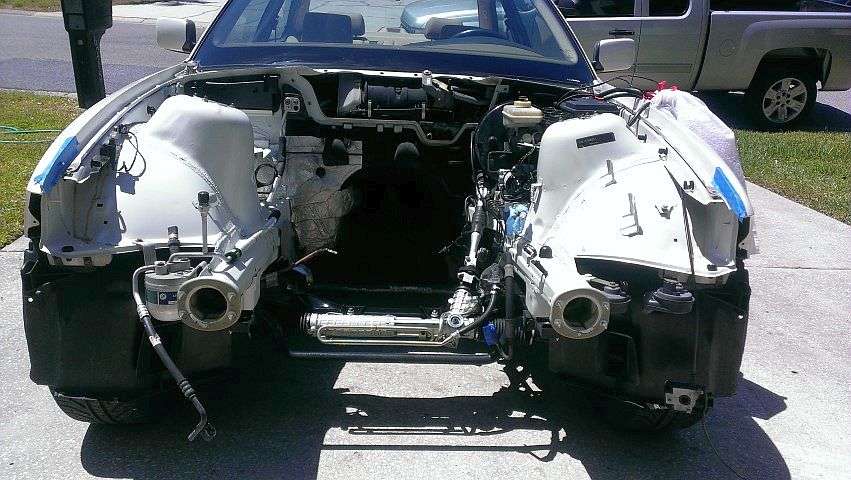
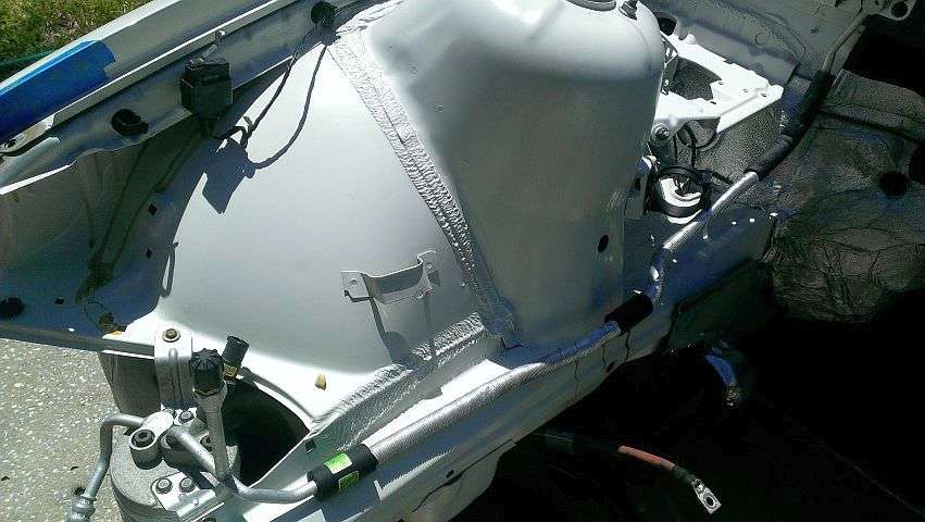
Also, got the car out of the garage and cleaned under the hood. Gunk, Purple Power a brush and a power washer. I think it came out great! It took three of use to push it up the sloped driveway back into the garage...and it was still a chore.
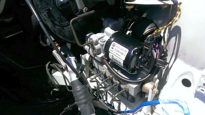
Also, got the car out of the garage and cleaned under the hood. Gunk, Purple Power a brush and a power washer. I think it came out great! It took three of use to push it up the sloped driveway back into the garage...and it was still a chore.

 04-19-2014 | 01:32 PM
#28
My engine was in one of their yards in North Carolina but they'll ship from yard to yard at no additional charge. They shipped it to the Crystal River yard, which is only an hour from here. I believe it took three days or less.
Tipsy
04-26-2014 | 01:09 PM
#29
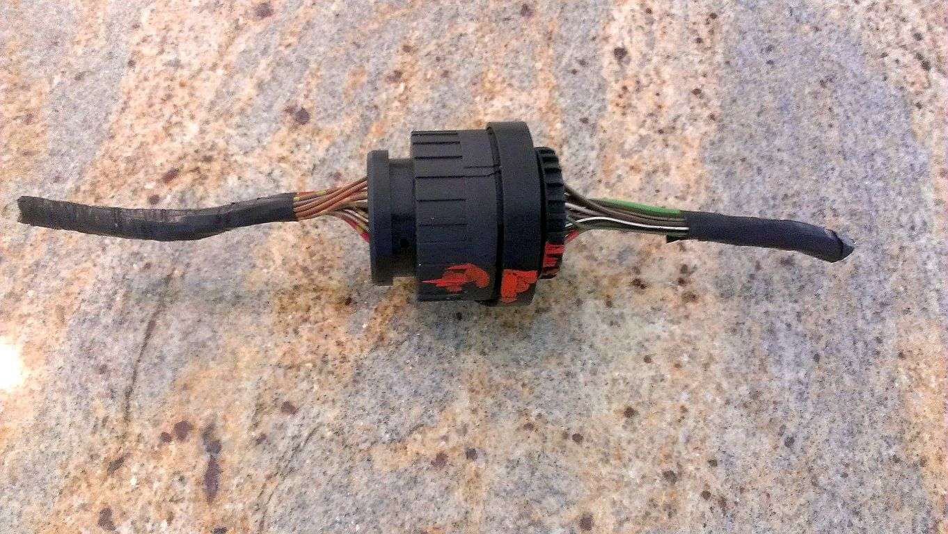
Picked up a couple of X20 style connectors to make an ABS pump extension harness. $6 at the pick-n-pull...gotta love it. I think I got one half from a seven series and the other from an E36, but they're the same type of connector and need to be completely repinned anyway.
For the BMW swappers; where have you guys been sourcing your pins for these connectors?
Also, for those of you who are using an F-Body T-56 and are in need of a E36 3.91 LSD, I know of one in the Clearwater (FL) area. PM me and I'll hook you up. After playing with the gearing calculator, it looks like a 3.23 will wok better with my GTO T56.
Won't be too much progress in the near future; I'll be on the road for at least the next three weeks.
Tipsy
05-19-2014 | 06:53 PM
#30

Registered User
Joined: May 2014
Posts: 1
Likes: 0
Received 0 Likes
on
0 Posts
Hey Tipsy,
This looks like a great start to your project. Have you called your cool friend in Jax to come help wrap things up yet? I spoke to him today and he said he's psyched to help.
Post more pics!
This looks like a great start to your project. Have you called your cool friend in Jax to come help wrap things up yet? I spoke to him today and he said he's psyched to help.
Post more pics!
05-19-2014 | 09:44 PM
#31
I'm back in FL at the end of the month...just in time for the garage to be 100°F+. Hopefully, I can make some progress. I want to get the vacuum booster removed and fab a bracket for the Mustang hydroboost. I can definitely use another set of hands (if you know of anyone willing to help).
Tipsy
05-19-2014 | 10:26 PM
#32
Now that I'm thinking about the hydroboost;
In the interest of making things more difficult than they need to be, I'm wondering if anyone has a suggestion for CAD design freeware...that's easy to use for someone with ZERO CAD experience? And also, looking for someplace that can create a one-off aluminum CNC'd part from said CAD design, for a reasonable cost?
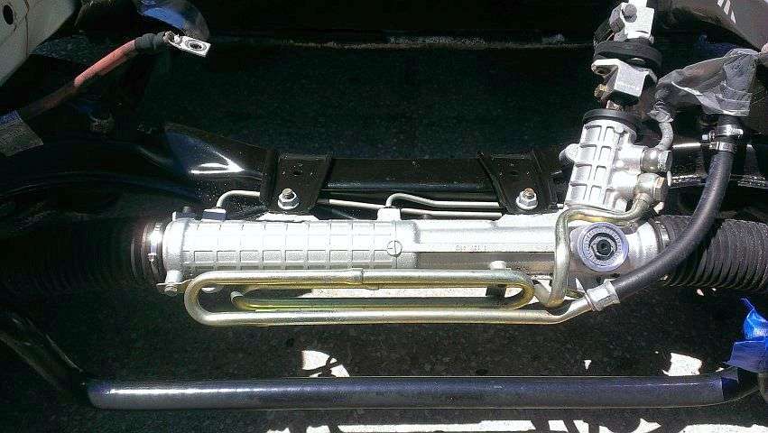
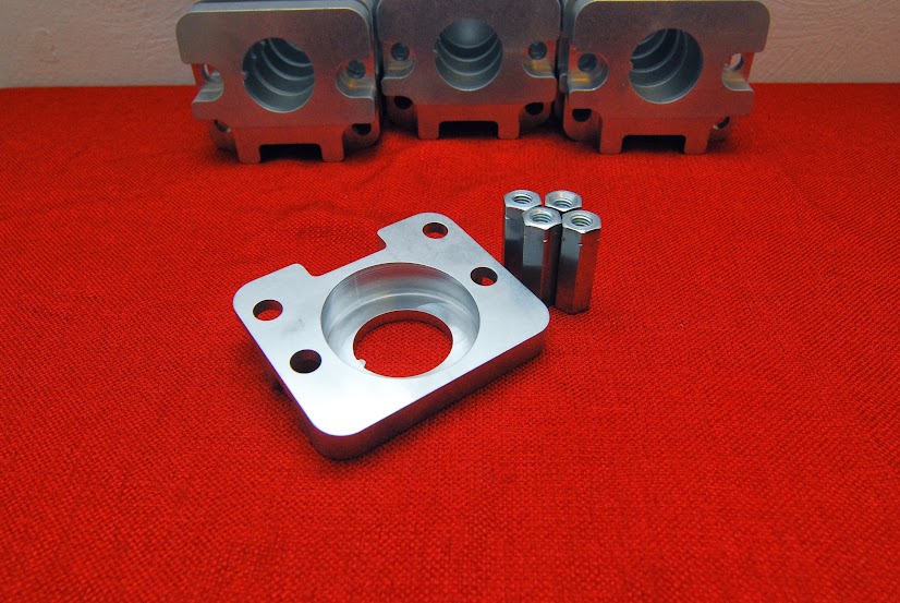
I'd like to create an aluminum bracket for the Mustang hydroboost unit, very similar to the one pictured below (this one is for a GM "A" Body). As you can see, the retaining nut is recessed in the back of the bracket and there is a key-way to "clock" the hydroboost correctly. I'm not sure, but I might need to offset the center hole a bit in order to clear the strut tower. In any case, I was thinking I could mock something up from wood, and then transfer the dimensions into CAD and have it fabbed.
Tipsy

In the interest of making things more difficult than they need to be, I'm wondering if anyone has a suggestion for CAD design freeware...that's easy to use for someone with ZERO CAD experience? And also, looking for someplace that can create a one-off aluminum CNC'd part from said CAD design, for a reasonable cost?
I'd like to create an aluminum bracket for the Mustang hydroboost unit, very similar to the one pictured below (this one is for a GM "A" Body). As you can see, the retaining nut is recessed in the back of the bracket and there is a key-way to "clock" the hydroboost correctly. I'm not sure, but I might need to offset the center hole a bit in order to clear the strut tower. In any case, I was thinking I could mock something up from wood, and then transfer the dimensions into CAD and have it fabbed.
Tipsy
05-20-2014 | 07:52 AM
#34
I'm still not sure whether I'll try to adapt a stock style clevis to connect the hydroboost to the brake pedal, or if keep the "eye" that's on the hydroboost and somehow attach that to the brake pedal.
Tipsy
05-20-2014 | 10:39 AM
#35
I set mine up to keep the brake fluid reservoir level. This involved a bracket at the firewall that effectively tilted the front of the hydroboost setup down and into the shock tower. It may not happen if you go directly to the firewall, but the angle of the reservoir isn't acceptable in my opinion. The bracket that I built isn't very thick, max of 1" at the thickest part. The rod coming out of my hydroboost didn't line up directly with the brake pedal. I cut the eyelet off of the original booster and welded it parallel to the hydroboost rod. This corrected the misalignment and allowed the use of the original hardware.
05-20-2014 | 11:53 AM
#36
I set mine up to keep the brake fluid reservoir level. This involved a bracket at the firewall that effectively tilted the front of the hydroboost setup down and into the shock tower. It may not happen if you go directly to the firewall, but the angle of the reservoir isn't acceptable in my opinion. The bracket that I built isn't very thick, max of 1" at the thickest part. The rod coming out of my hydroboost didn't line up directly with the brake pedal. I cut the eyelet off of the original booster and welded it parallel to the hydroboost rod. This corrected the misalignment and allowed the use of the original hardware.
Still undecided whether I'll adapt a clevis or retain the Mustang "eyelet" and attach it to the side of the brake pedal.
Tipsy
 06-03-2014 | 05:10 PM
#39
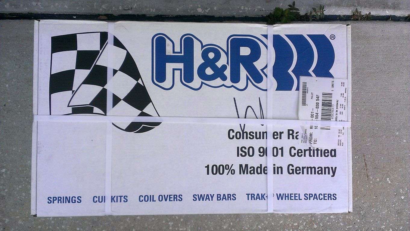
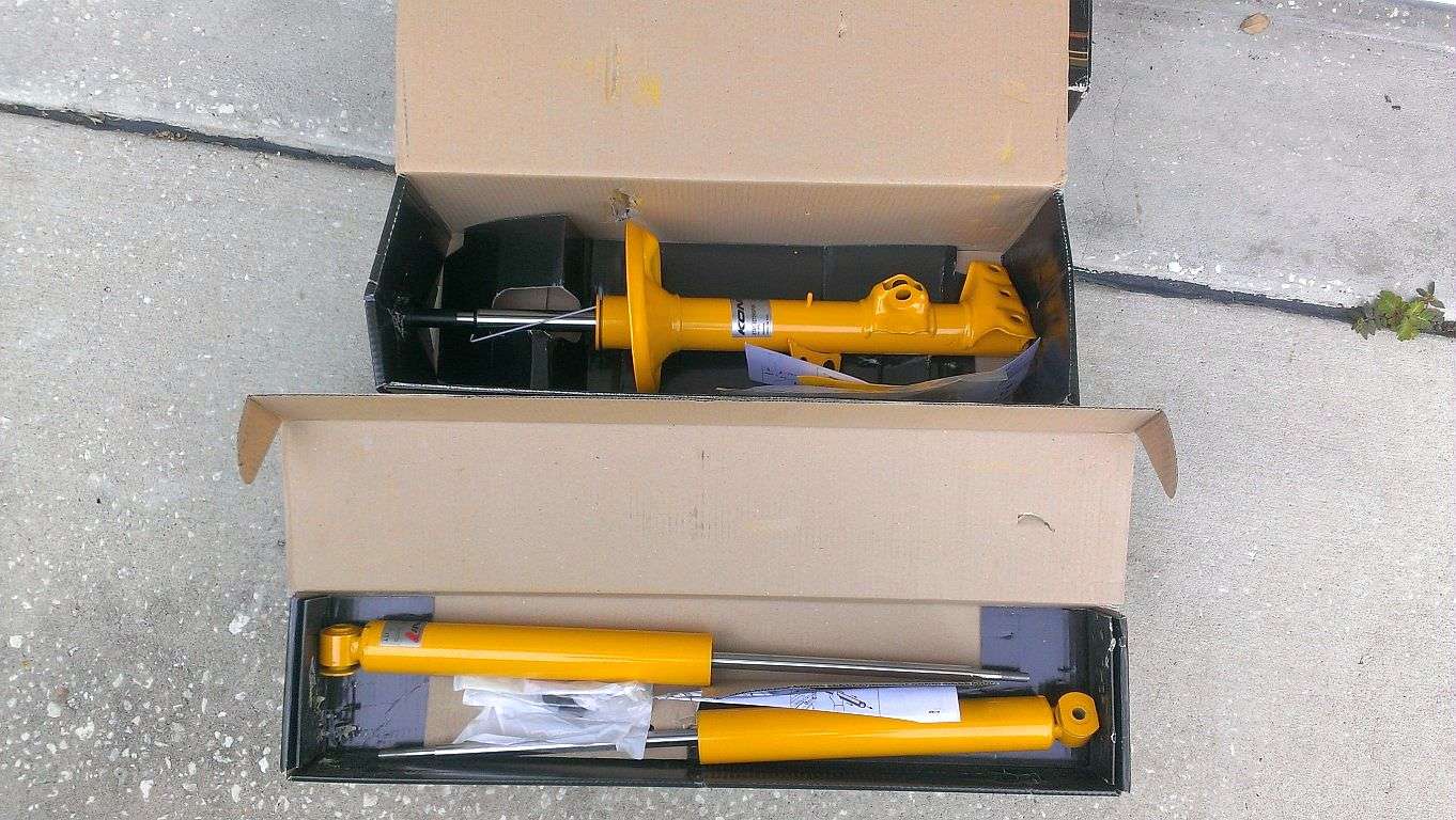
Finally back home. While I was traveling, I ordered a bunch of parts. Reading about E36 suspensions is enough to make your head spin. In the end, I decided to go with H&R Sport springs and Koni adjustable struts and shocks. I have no idea how I'll end up using this car but for the time being, I didn't see the need for any kind of coil-over setup. I'm hoping the Sport springs result in a nice stance. I don't want it "slammed" but I don't want that ugly gap between the tire and fender lip. We shall see. I also ordered an Improved Racing oil pan baffle. Again, I don't know if I'll get into autocross, but I figured I might as well install the baffle now, while it's easy.
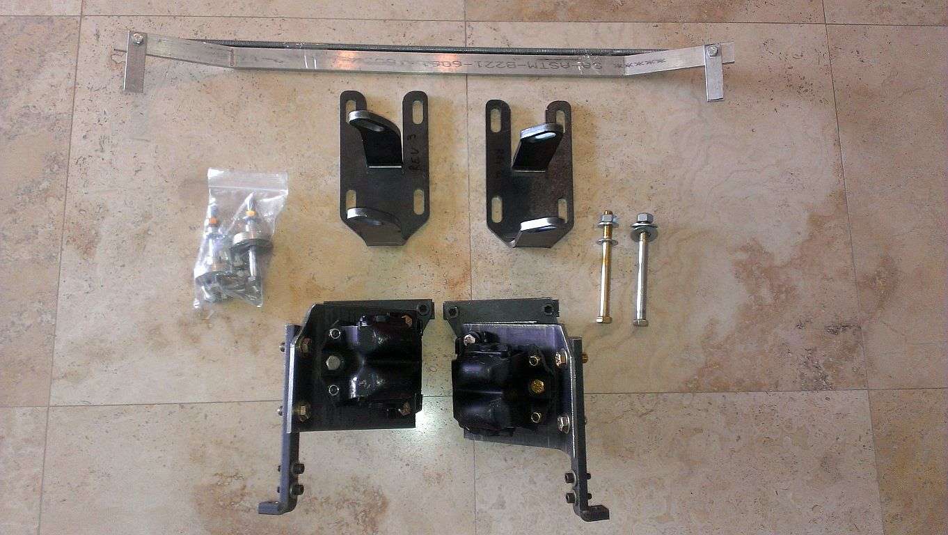
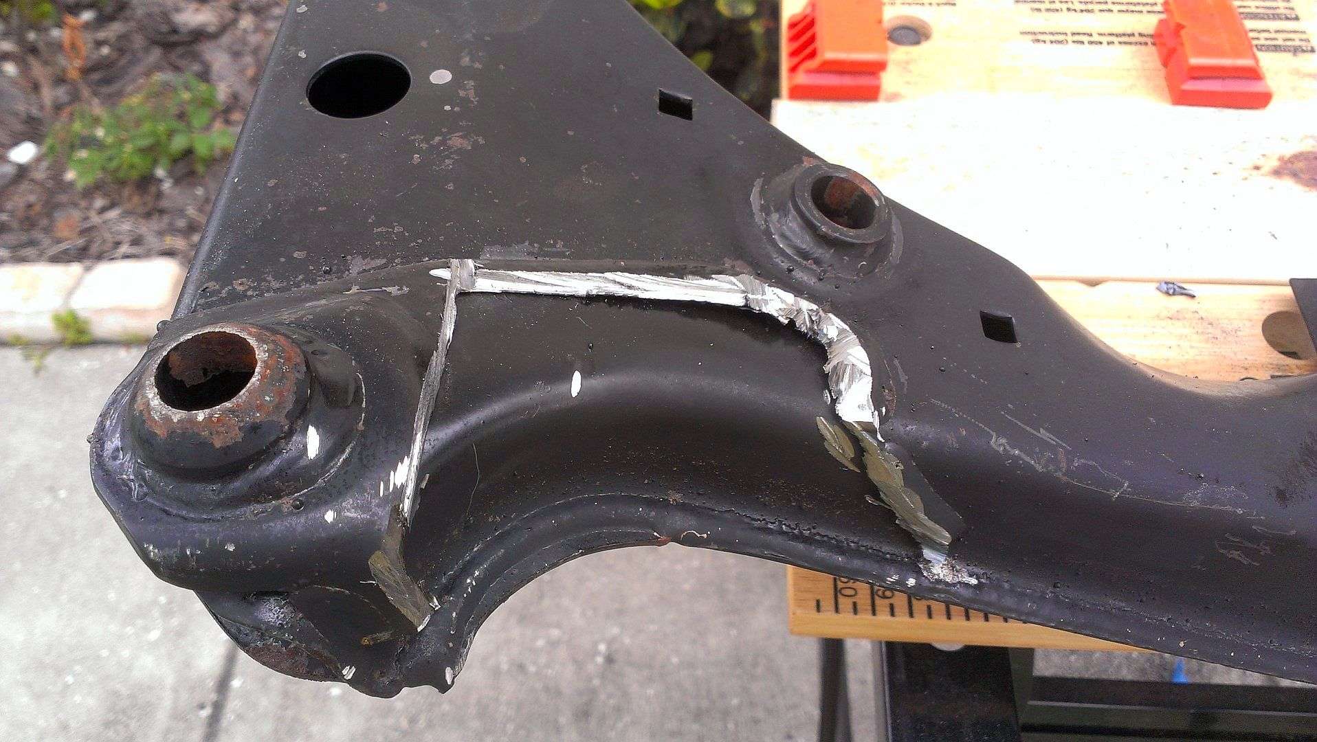
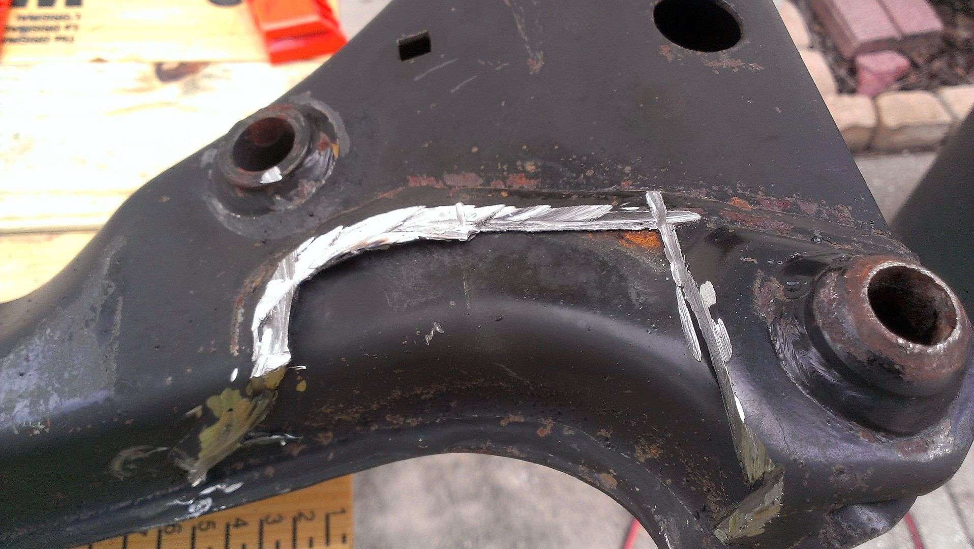
The JTR kit requires modifying the front subframe to accept their motor mounts (see here). I decided to buy a spare subframe to modify rather than to disassemble the front suspension, leaving the car immobile any longer than necessary...and also risk screwing up my only subframe. Good decision because I was ham-handed and screwed up my first attempt at making the necessary cuts. I thought about my approach and gave it another try on the other end of the subframe (knowing this one was now junk and having little to lose). My second try came out much better. So, I bought yet another front subframe (they're not too expensive) and got to work on it today. I think it came out pretty damn good. My tool of choice was a 4 1/2" DeWalt angle grinder with a metal cutoff disc to make the cuts and a 40 grit flapper disc to grind it smooth. Those flapper discs rock!
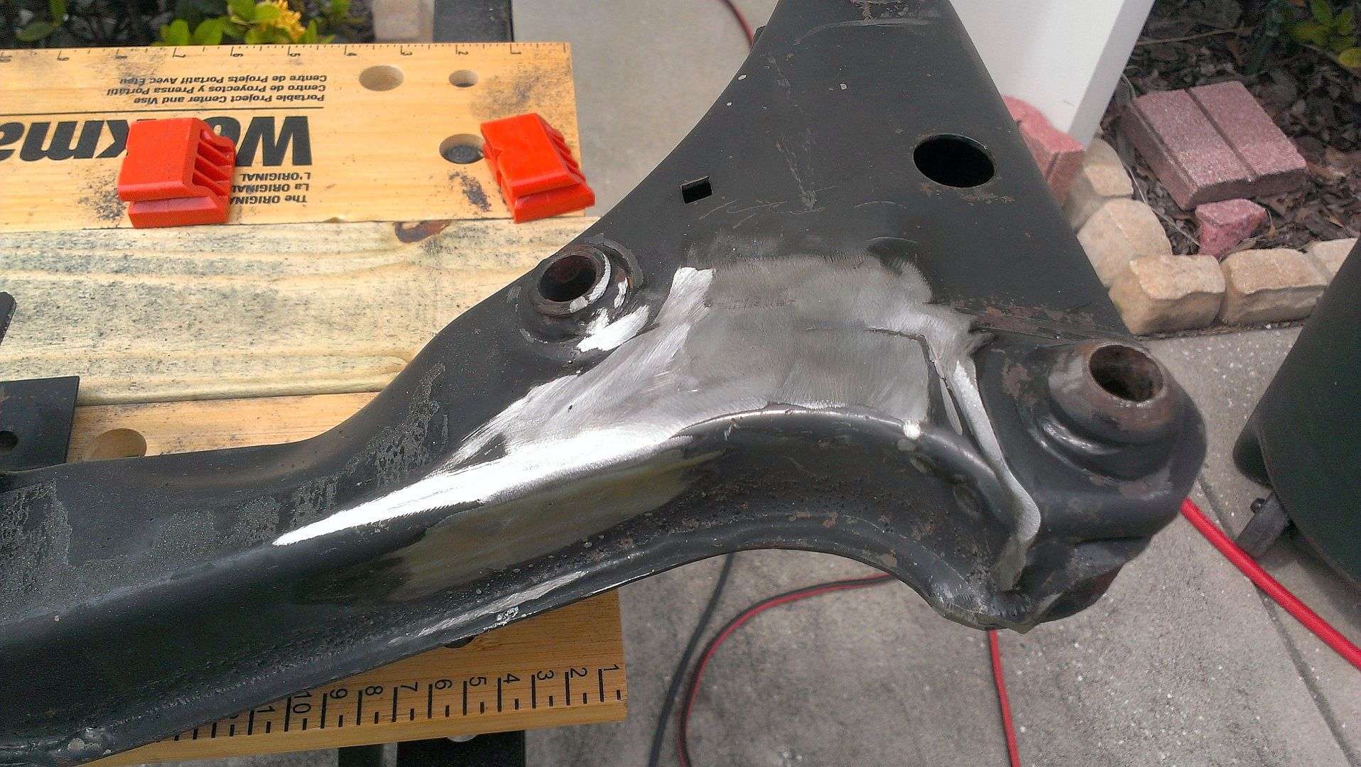
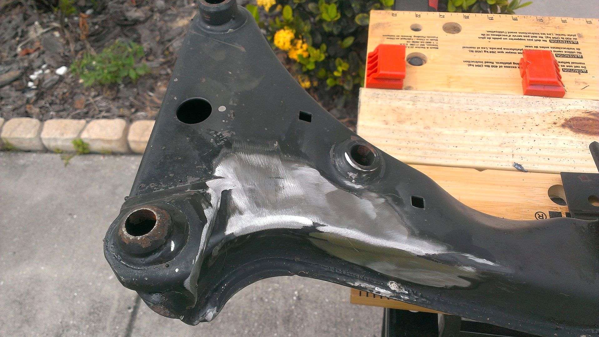
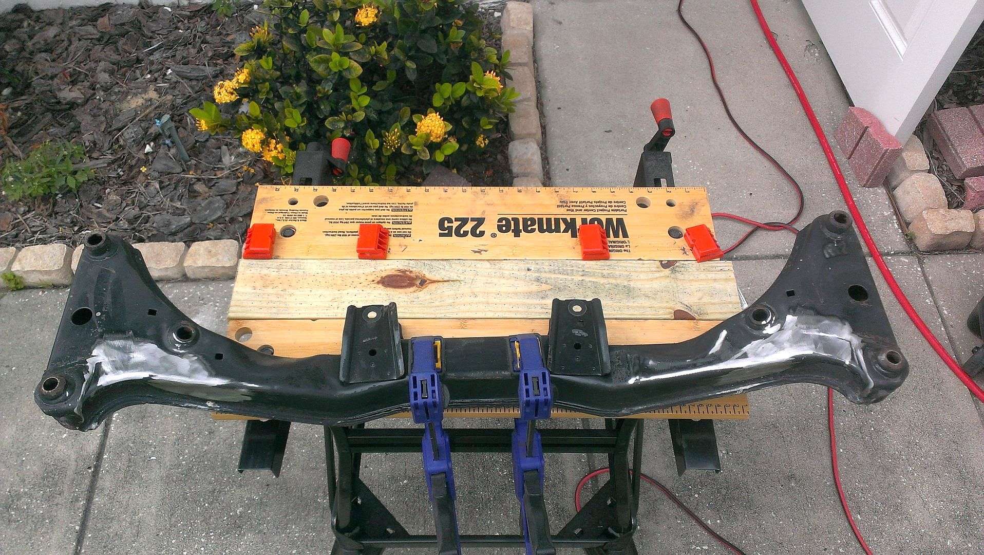
Today, I ordered Lemforder tie rods and '95 M3 Lemforder lower control arms. I have to disassemble the entire front end for the subframe modification so I figured I might as well reassemble it with all new bits.
Over the next couple of days, I'll finish the subframe modifications and get to work swapping the cam, valve springs and oil pan on the LS2.
Tipsy
The JTR kit requires modifying the front subframe to accept their motor mounts (see here). I decided to buy a spare subframe to modify rather than to disassemble the front suspension, leaving the car immobile any longer than necessary...and also risk screwing up my only subframe. Good decision because I was ham-handed and screwed up my first attempt at making the necessary cuts. I thought about my approach and gave it another try on the other end of the subframe (knowing this one was now junk and having little to lose). My second try came out much better. So, I bought yet another front subframe (they're not too expensive) and got to work on it today. I think it came out pretty damn good. My tool of choice was a 4 1/2" DeWalt angle grinder with a metal cutoff disc to make the cuts and a 40 grit flapper disc to grind it smooth. Those flapper discs rock!
Today, I ordered Lemforder tie rods and '95 M3 Lemforder lower control arms. I have to disassemble the entire front end for the subframe modification so I figured I might as well reassemble it with all new bits.
Over the next couple of days, I'll finish the subframe modifications and get to work swapping the cam, valve springs and oil pan on the LS2.
Tipsy
06-03-2014 | 06:30 PM
#40

Now that I'm thinking about the hydroboost;
In the interest of making things more difficult than they need to be, I'm wondering if anyone has a suggestion for CAD design freeware...that's easy to use for someone with ZERO CAD experience? And also, looking for someplace that can create a one-off aluminum CNC'd part from said CAD design, for a reasonable cost?
I'd like to create an aluminum bracket for the Mustang hydroboost unit, very similar to the one pictured below (this one is for a GM "A" Body). As you can see, the retaining nut is recessed in the back of the bracket and there is a key-way to "clock" the hydroboost correctly. I'm not sure, but I might need to offset the center hole a bit in order to clear the strut tower. In any case, I was thinking I could mock something up from wood, and then transfer the dimensions into CAD and have it fabbed.
Tipsy
http://www.emachineshop.com/
download their software, design the part, and it will quote price and expected delivery time on having it made.