When you click on links to various merchants on this site and make a purchase, this can result in this site earning a commission. Affiliate programs and affiliations include, but are not limited to, the eBay Partner Network.
Dual cooling fan wiring with Trinary Switch and LS1 PCM
I have a 68 camaro equipped with LS6 and OEM PCM ( blue and red connectors) and a binary switch.
I am a bit annoyed with fans operation way too early. For example, the passenger side fan comes on within a few minutes of engine start up. I checked the temperature with infrared gun at the radiator inlet, it reads about 118 degrees F, and the driver side fan comes on shortly after the first fan, and at temp around 125 degrees F.
Both fans come on once I run the AC.
I took my car to a tuner to do the dyno tuning and asked to check the activation of the fans. I was surprised bu saying there was no any indication on PCM for the fans settings. I guess he did not check properly.
I have the temperature sending unit at passenger side head for temperature gauge only. That is why I believe the only way the fans are being activated is through the low and hi temperature wires ( dark green and dark blue).
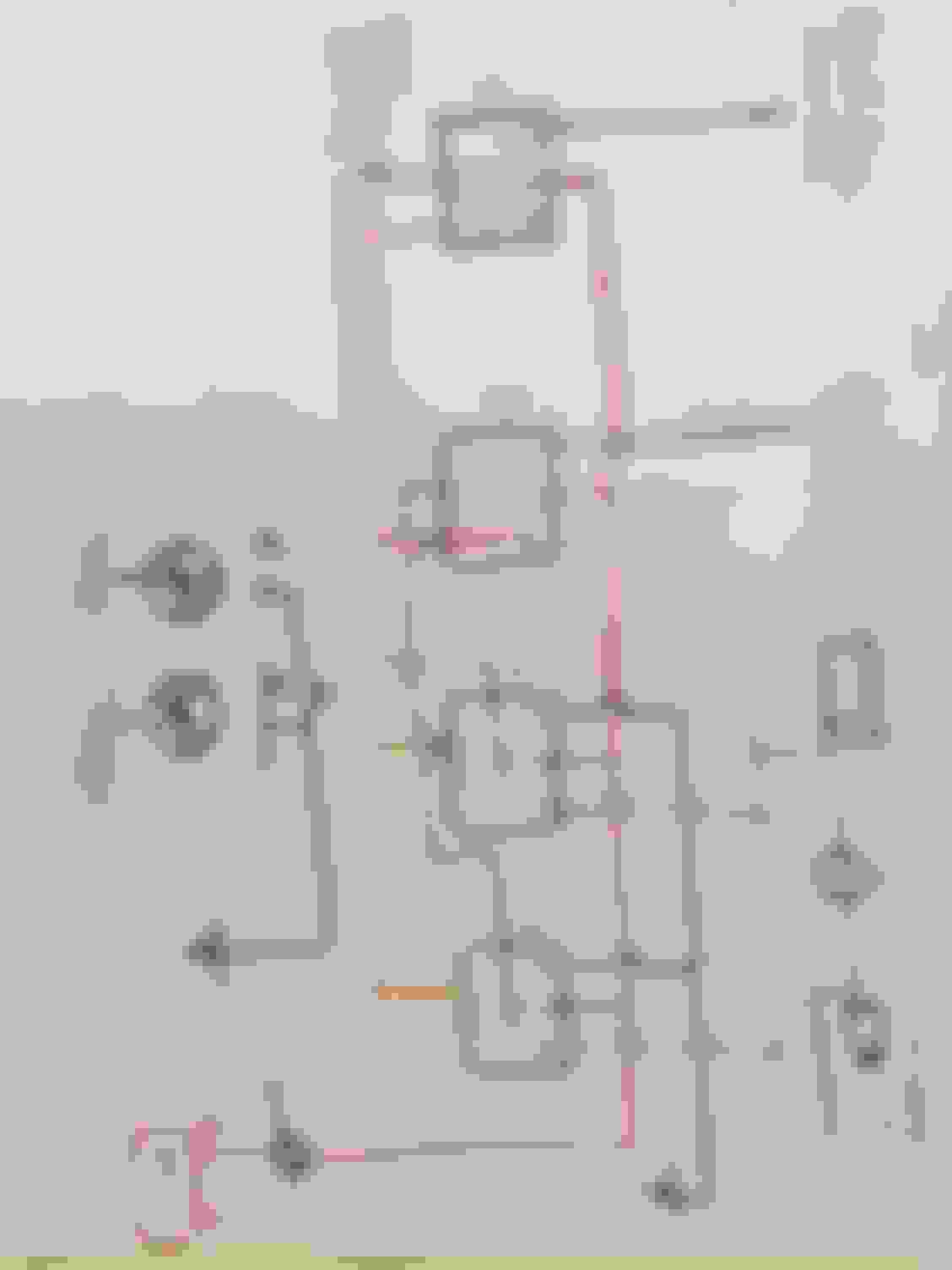
I have drown a rough schematic of the cooling fan relay wiring if someone could interpret how the fans operate based on the wiring diagram.
Just would like to know what changes should I make to make the fans operate properly and where the trinary switch wire for the relay will be connected.
Use the normal ecu control to star fan 1.
Use a trinary switch and temp control (high temp) to control fan 2.
I use the 411 ecu hi control (recirc pinout) for fan 2 on mine, but others got codes with the trinary grounding the relay. I used a variable temp sensor on my 05 for high temp/trinary activation.
The fan does not need to be on all the time with AC.
Well I found the below wiring diagram for wiring the cooling fans in one of the posts in this forum. The pin numbers for the green and blue wires coming out of the ECU are similar to mine.
So I am going to rewire mine similar to the below diagram and splice the trinary switch wire into pin 85 of relay 1 to activate both fans at low speed whenever high pressure is detected by the trinary switch.

 06-14-2019, 02:02 PM