When you click on links to various merchants on this site and make a purchase, this can result in this site earning a commission. Affiliate programs and affiliations include, but are not limited to, the eBay Partner Network.
I'm on my my kinda-annual Maui vacation.. which awesomely enough is when I get my best car research done.. no distractions of work or friends back home, just reading and relaxing.
With removing the single turbo hotside crossover from the equation, I now have freed up a good 3+" of depth between the current radiator/fan setup and the next closest engine stuff, which will now be the waterpump pulley.
From looking back at my build thread and some measurement pics, looks like I can shoehorn a radiator of 31.5" overall width in between the frame horns. Assuming no subframe modifications (which I have no issue with doing, I'm just working with my baseline known constraints for now) a C&R dual-row radiator of overall size 31"x19" should fit, with a core size of 28"x18.6"x2.25". This core size would allow me to shoehorn in 16" and 14" fans as a dual fan setup, with the extra core height past the standard 15-16" high core. What I plan to do is place the rad closer to the hood, with ducting and paneling blocking off all areas of the core support to the hood. There's a good 1-2" high by maybe 48" long gap across the core support to the hood that I need to seal off so all that air turns into a high pressure zone in front of the core support. I'm going to completely hack up the core support to make this rad and a new intercooler fit.
For intercooler, I'm going to go with dual 2.5" (8.8 square inch x-sectional area) inlets on the bottom, feeding a vertical-flow intercooler, with a single 3.5" top outlet (8.9 square inch x-sectional area). I originally liked the idea of a single outlet in the center of the intercooler top, directly feeding the throttlebody, but I think the extra 3-4" of height in this area across the length of 30+" is too valuable as prime real-estate for the upsized radiator, to interrupt it and require a shorter radiator core by using a single top intercooler outlet.
The common intercooler options these days seems to be Treadstone or CXRacing (or Bell, but $$ and totally custom cores) both have the appearance of China quality. I'm not expecting there to be a massive flow difference between a mid-level and cheapy intercooler, but I think I'd rather reduce my initial costs and get an appropriately sized bare core if I can, and sculpt my own end tanks. That being said, the Treadstone TRTT (25"x6"x3.5" core, 1000hp claimed capability) or TRTT9 (25"x9"x3.5" core, 1300hp claimed capability) intercoolers could work.. but for ~$5-550 USD I'm just not convinced..
The other possibility is just a core from Vibrant, which there are multiple options. One example that is the closest to the Treadstone size is 27"x6"x4.5" core that is claimed capable of flowing/cooling only 900hp..
Based on my ghetto MS Paint measurements of my grill area, ideally I'd like an intercooler core of 26-28" wide, around 8" high (I think it's about 7.5" between my bumper trim piece and the leading edge of the hood). I'm undecided whether 3.5" thick would cut it or 4.5" would be needed to help with pressure loss. I' thinking if there are 26-28"-width worth of flow path options for the air, and the air is only being jammed thru 8" vertical length of intercooler, then 3.5" thickness shouldn't be a restriction. However I'll have the room for 4.5" thickness. Just thinking out loud here I guess.
Joe I can't help but think you are re re doing what is already done. What problem(s) are you trying to overcome from your existing single turbo setup? What are your primary goals for this new setup? Improved response/driveability? More power? One-upping Mark (in which case, can I suggest a 3rd turbo or an inline supercharger for outrageousness)?
Hey Clint.. great questions, I appreciate the fact checking as I've wondered the same questions for the last couple years until I finally decided after much thought that changing up my setup was the only viable solution, let me try to explain:
1) first and foremost is cooling, for a couple reasons:
- current turbo hotside pipes wrap around in front of the waterpump and have limited my radiator thickness.. I physically can't put in a thicker rad and fan stack without removing the grill and pushing the intercooler forwad above the bumper, or removing the hotside crossover piping
- to reduce underhood pressure as much as possible and make the radiator the most efficient, I need inner fenders.. with my low ride height I simply cannot fit an inner fender in the passenger side with the 275 tire at full left steering lock
2) power/response:
- I'm at the physical limit of turbo that I can fit under the hood in the current location.. remember I don't have subframe bushings to my hood is now that 3/4" lower to the engine.. the max turbo size would be a Precision 78/75 but that's only a small step up from current
- for the single setup I tried to keep the hot piping similar lengths side to side, but there is still ~3ft of passenger side piping and probably 4+ft of driver side piping, at 2.5" OD pipe it's oversized and slowing exhaust velocity down, and likely what is introducing lag from what I've read
- I want to go from a horizontal flow intercooler to a vertical flow to spread the airflow path wider and shorter for less pressure drop..
- I need to remake the exhaust anyways, so I might as well start that project as dual 3.5" pipes from two turbine housings instead of a single 4" pipe from one turbo and possibly redo later
The upsides I can see from going single to twins:
- frees up several inches of room between the rad and the waterpump, allowing a thicker but also taller rad core that fits an upsized dual fan setup, to help pull air thru the thicker core
- significantly shorter turbo hotside (from ~4ft @ 2.375" ID per side to hopefully <1ft @ 2.25" ID)
- better airflow overall (for if I decide to go bigger cubes now or later on) by having dual 2.5" compressor outlets to single 3.5" feeding the throttlebody
- turbos moved forward allows more room for inner fenders, which are essential for lowering the underhood pressure and making the pressure drop across the rad larger
- I've always liked the idea of twins, even since before Mark started his project (I'll naturally be a tad larger than his 6265 Precisions, just because)
- Lastly.. why not? If I've done a single turbo setup to pretty good success (self admittedly, for a first ever attempt that I fabricated in my early 20's) there's only one direction to naturally progress to!
Well it finally happened, started tearing apart the car!
Here's an interesting comparison between LSA CTS-V (left) and LS3 Corvette (right) driver side manifolds..
I like that the CTS-V manifold angles the flange tighter and more perpendicular to the head, tucking it in closer to the edge, however the bends are a bit more gradual leaving the head so the manifolds runners are ~3/8" more outboard that the LS3. I'm beginning to see that it's going to be quite tight on the driver side, snaking the downpipe between the manifold, steering box, subframe, motormount, and UCA cross-shaft, hopefully this extra bulk on the CTV-S manifold doesn't hinder anything.
CTS-V manifold height off the head, in line with the mounting hole..
And same location on LS3 Vette manifold showing the the extra clearance..
Here you can see how how tight the manifold is to the head. I'm going to try moving the alternator inboard closer to the throttlebody, to move it away from heat. I was also thinking I may try to relocate the alternator to the lower passenger side (like an AC compressor) and notch the subframe. But that would make the belt routing pretty screwy.. I'll evaluate that fitment when I have the engine bay more apart.
Next I made a super-precision turbo stand for my old blown-up TC-76... definitely Roadkill-approved. It has a T4 housing, but the housing is tiny, so I'm using it as a rough approximation.
Check out how short the hotside piping will be! Wastegate likely be put in a direct path right off the only bend. Was using a cheap-n-easy 2.5" aluminum bend to mock up the sizing, before I order SS321 material...
And something I've been curious about for a while.. exactly how much more vertical room is there to grow the size of the radiator... well there's a lot! Used wood to mock up a 3" core, slammed forward to the rad support, and measured at the center as well as the ends of the rad. You can see this placement relative to the hood bracing. Looks like I have an extra 4.25" height on top of the current 16.5" high rad, so total height before it'll hit the underhood bracing is 20.75". And that's with no subframe bushings, so for anyone else it could be as much as 21.5" high. So I'll start thinking about using a 19-19.5" high by 28" wide core radiator, and totally seal the entire rad support to the hood underside with a "dam" on top of the rad support and then a rubber seal on top of that, maybe something similar to a universal door seal.
Thanks for putting those thoughts down. Improve cooling. Reduce lag. Add power. I can get behind those goals!
How would you say the lag was before? It would be interesting to see an overlay run chart of throttle position and boost or acceleration against time, to see how much delay there is between dropping the shoe and moving the car. I hate the feeling of waiting when I push the throttle - I want snap performance. I also hate when a turbo setup isn't matched properly and you get a sudden surge in power as the engine creeps up on an RPM/load window where boost starts to kick in. I really like how my N/A setup responds right now - very crisp throttle response, but not nearly the power I'm sure.
Nice to see you'll have vertical room to grow the radiator, but with twins I really like the symmetry of an intake tube that goes straight over the top of the radiator down to the inter cooler. For example, I really like Chevy406's setup:
Last edited by -TheBandit-; 11-08-2017 at 11:02 AM.
People laugh when I say that one of the driving reasons for twins is to gain room to make/install inner fenders, but when I break down the waterfall effect of engine bay pressure combined with more rad/fan/intercooler room, they get it.
The lag before was existent, but not unbearable. I would say if I started in 2nd gear at 2000rpm, it would go something like this:
2000-2800rpm = boost instantly spikes from pulling vacuum to 0 or even 1 psi boost
2800-3000rpm = 2-3psi
3000-3400rpm = 5-6psi
3400-3800rpm = 6-10psi
3800-4500rpm = 10-14psi
4500-5000rpm = 15-16psi
5000-6200rpm = steady 16psi, occasional 17psi, but the acceleration dies off due to backpressure from restrictive 2.5" dual exhaust, I'm sure
I know what you mean about the symmetry of twins and then a centered 3.5" charge pipe going right into the throttlebody. I'm still not counting it out, but from my above wooden measurements, it looks like I'd have to limit myself to a 16.5" high radiator core located in the same spot as current, in order to bend a 3.5" round pipe over it and have ~0.25" gap below the pipe and 0.5" gap above to the hood. I've also considered fabricating an aluminum charge pipe version of the cobra-looking Corvette cold air intake tubes (like below), but I'd have to squish it quite a bit just to gain room to increase the rad core 1-1.5" taller.
On Monday I put in an order for some weld elbows of several sizes, schedules, and bend radii, to test fit and see which ones will work for my envisioned turbo piping setup. I figured if I'm shipping some stuff to my PO box in the states, might as well ship some more, and I ordered a bunch of 2.5" and 3.5" intercooler couplers, elbows, and piping that I know I'll need anyways.
It was also very hard for me to not pull the trigger on a new rad+fans setup last night as I researched setups for hours, but I knew I needed to measure real life with as many items mocked up in place. I'll hopefully remove the current intercooler and rad this weekend, and mock up hotside piping as well as routes and clearances for charge piping, to figure out the thickest/tallest rad+fans combo I could get.
Unless proven/measured otherwise, my current thinking is a 2-row 2-pass C&R radiator (P/N 802-31191) and likely dual 14" fan, but maybe a single 18" fan. It's terrible trying to choose fans online based off all the sketchy CFM ratings (like Zirgo.. 3600cfm and 10amp draw? Yeah right!).
Possible fan options currently are:
1) dual Spal 1900cfm 21amp 14" fans (P/N 30102042). But Spal consistently has tech specs for all their fans, and although 2400cfm isn't the highest draw I found for a fan, it's from a company with good reviews (more specifically, a lack of reviews say their CFM's are full of ****) and is the highest amp draw I could find.
2) dual Derale 2200cfm 22amp fans (P/N 18214) as I've good success with that brand and that's the highest CFM 14" fan they make, and it's a good price.
3) for a single 18" fan, there's very limited options available.. I would likely be looking at an OEM SUV or truck fan, so it would be hard to get CFM/amperage data for one. A fan that comes to mind is the Cadillac SRX fan (I forget the exact details at the moment) but they're crazy expensive at I think $600, and require PWM management.. but apparently pull crazy amounts of air. I'll search my subscriptions and try to find the Mark Steilow build thread that has more specific info for it
EDIT: looks like the fan I was thinking of is from a Cadillac SRX, and is huge (fan shroud is 23"x24"). But here's some interesting info anyways...
I haven't put much thought into the aerodynamics of inner fenders, but they sure keep things a lot cleaner under the hood. As far as the intake goes, I'm sure you could fabricate some round-to-rectangular/ovel ductwork that would help you get over the radiator and maximize radiator size - I think that's a perfectly acceptable solution so why not plan for it and leave yourself some room to execute? If you want a 3.5" diameter intake, you could get a similar cross sectional area with a 2.5x4" or 2"x5" rectangle. So leave yourself maybe 3" up top? You are going to get much better cooling out of a thicker core aluminum radiator than what you currently have, even if you don't increase the area.
That's a good point. I'm really not finding any decent radiators taller than 18.5" core height, especially high-quantity units at an acceptable price from a reputable company. So if I get a 31"x19" C&R rad, which has a 28"x18.5" core, that will still fit between my subframe rails and I could hack the bottom of the rad support up to allow the radiator to be 1" lower, so the 2" taller-than-current core will only be 1" taller than current, which will maintain decent room for a centered charge pipe.
However, there's also a point that I forgot to mention....... for some reason the centered charge pipe looks kindof elephant-trunk-like to me.. for some reason it just doesn't appeal strongly to me despite the centeredness and symmetry being ideal. Also.. which side of the nicely centered pipe would the BOV go on? There won't be room for it oriented/hidden underneath due to accessories and rad fans.
I'm glad you're doing all of this radiator work so I can steal it before next summer. I also got under the front of mine to mock up a cardboard air dam, and there's a bit of work to be done to account for the gaps between the radiator support-subframe, in addition to the support not being straight at the bottom.
Last edited by hookemdevils22; 11-08-2017 at 02:06 PM.
Sounds good. I'm still planning on getting a nice digital manometer, so I may do a before-after test of the current S10 single core rad setup with dual 13" Derale fans, and whatever the new setup ends up being, to compare the difference in fan suction with the increase in rad core thickness.
I see what you're saying about the elephant trunk. That is why you need to go to a dual throttle body setup with two charge pipes going over the radiator to a common intercooler If for some reason that's not an option, flattening or ovaling out a center pipe should take some of that elephant trunk look away. Or you could try moving to an oval throttle body and charge tube like what was used on the old LT1s and TPI engines. It would still be center trunk-like but not so much a round noodle.
It took me 2-3 days off and on to read this whole build thread and I'm glad I did! Many props to you for your engineering prowless. I thought I had read all the big build thread around Nova's was kinda of surprised not to see this on SNS.
I don't have much to offer as most of what your doing is well over my head. I can agree with you about the inner fenders they should be on, if not from a airflow perspective but from keeping debris out of the engine area as well as adding proper structure to the fenders themselves.
Did I miss where you notched the front sub frame for your 275 tires? I saw what you were doing from a steering link perspective, I have to re-read that a few times as I may have some questions that I may like to apply to my 71 nova.
Thanks for the compliments! This car has been a long, educational process.. it's just been so fun mentally designing and then learning to fabricate everything for the car.
I was never really tempted to start a parallel thread on Steve's Nova Site, mainly because I was using the LS1tech picture uploader and it would have been way too much effort at the time to additionally upload all the pics to a 3rd party site. I'm glad I started that route on this site and continued with it, after all the Photobucket fuckery that happened. I did start a trimmed down summary thread on Lateral-G, but it never really caught on as I guess my build didn't have enough $4000+ wheelset with 15" Baer 6pistons, and Anvil and Marquez Designs parts with a paintjob from a forum-known painter.
For the 275 tires.. I didn't notch the subframe. Turns out that the mechanical steering lock for the box I have (to be honest, I don't even know the specs for it other than ~12.7:1) happens to occur right as the inside sidewalls are kissing the subframe rails, which is also at the exact time that the outside tire corners are touching the trimmed fender inner lips. So technically there isn't really a need to notch the subframe now as the system is reaching several mechanical limits all at the same time. Hell if I crank the steering wheel at full lock, then turn the engine off and the steering column locks the steering wheel, the wedging effect of the inside sidewalls on the subframe is enough to act as a parking brake.
That being said, I have thought about notching the subframe this winter when I take everything apart, for two reasons: 1) to future-proof front tire room while access to the subframe is easiest for cutting, welding, and painting. And 2) at the very least to create inboard room between the full-lock tire and the subframe rail for the future-fabricated sway bar arms.
A thought I had while trying to fall asleep last night.. could there be room to move the alternator from high driver side, to low passenger side? I'm still going to be running the truck accessories, which place the belt alignment 1.5" forward of the car setup.. I'm going to test fit to see if the truck alternator fits down low and left. Even if there's some notching required, I think I'll do it to get it out of the way visually as well as away from driver side turbo piping heat.
Jimbo.. how do you mean? Like his low and super slanted rad that made room for the turbo's in front of the accessory drive? I'd like to keep the core as vertical as possible, plus with the removal of the crossover pipe it has opened up loads of room. And I can't seem to find a reasonable off-the-shelf radiator solution taller than a ~18.5" core, so I'm still not limiting myself from being able to do a center charge pipe. I'm just leaning heavily away from a center pipe.
Well today was another productive and fun day in the garage.. and it wasn't even that cold! There was some good news and some bad news, luckily bad news is inconsequential.
The good news is actually just new parts I picked up. A random assortment of 3.5" tube and couplers, 4.0" tube and elbow, a random 2.5" bend and an old but unused 4" filter from my truck for mockup..
So the carbon 3.5" tube is just an experiment for a couple reasons: 1) mainly because the bend radius is tighter than the current setup's 3.0" tube, it should easily be able to handle the pressure and help keep post-intercooler temps down, and 3) because it looks cool and why not? If I end up using it, I will bond (using this crazy carbon-friendly epoxy we use at work) the elbow and straight together using a thin inside sleeve, and bond in ribbed ends so that the couplers don't blow off under pressure..
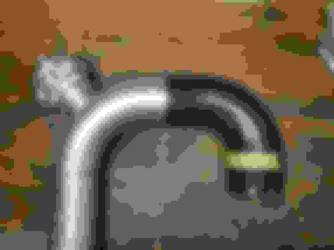
Here's a comparison of the current 3.0" charge pipe to a new 3.5" aluminum pipe, for comparison. The bend radius (CLR) is about 0.5" bigger on the 3.5" bend..
Here's a comparison of the current 3.0" pipe to the test 3.5" carbon elbow.. the CLR on the carbon is about 1.5" tighter than the 3.0" alloy pipe! The inside of the carbon is very nice and smooth, and is about 0.085" wall thickness.
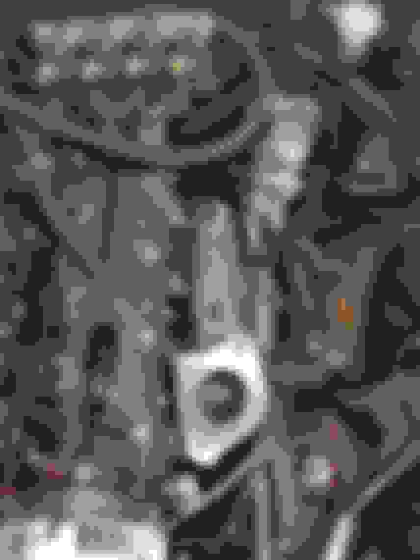
And some bad-but-whatever news.. I thought I had heard an exhaust leak a while ago, but just assumed I'd find a pinhole somewhere and easily plug weld it up. A little more than a pinhole! When I swapped from the Turbonetics TC-76 (which the piping was designed around) there wasn't any cracking. I remember the Precision 7675 being a bit tighter of a fit, and I was surprised I was even able to bolt it on without any downpipe mods. Well I guess it was preloading the wastegate via the downpipe when I tightened the downpipe to the turbo housing, as the crack started from that load direction. And look how gross those welds were! Such inferior work from 6+ years ago.... good riddance!
And more parts carnage.. here's some el cheapo Summit brand heat shielding.. the aluminum foil is just disintegrating off the insulation! I'll have to look into quality name brand stuff for the TT setup.
Next fun thing from today, confirmed that the alternator can definitely fit in the lower passenger side location.. even without notching the subframe.
However, with the alternator rotated so the output post on the backside rotated is decently far away from any surrounding metal, the 4-pin plug for the regulator is pointed right at the crossmember. So I may still notch the subframe for access room to that connected if I can't find a different orientation that works. Or maybe just find a 1-wire alternator and be done with it. But I'm happy that it physically fits with the truck accessory drive.
The final post from today is the most exciting, also picked up an assortment of stainless weld elbows, one of each, to see which ones fit best!
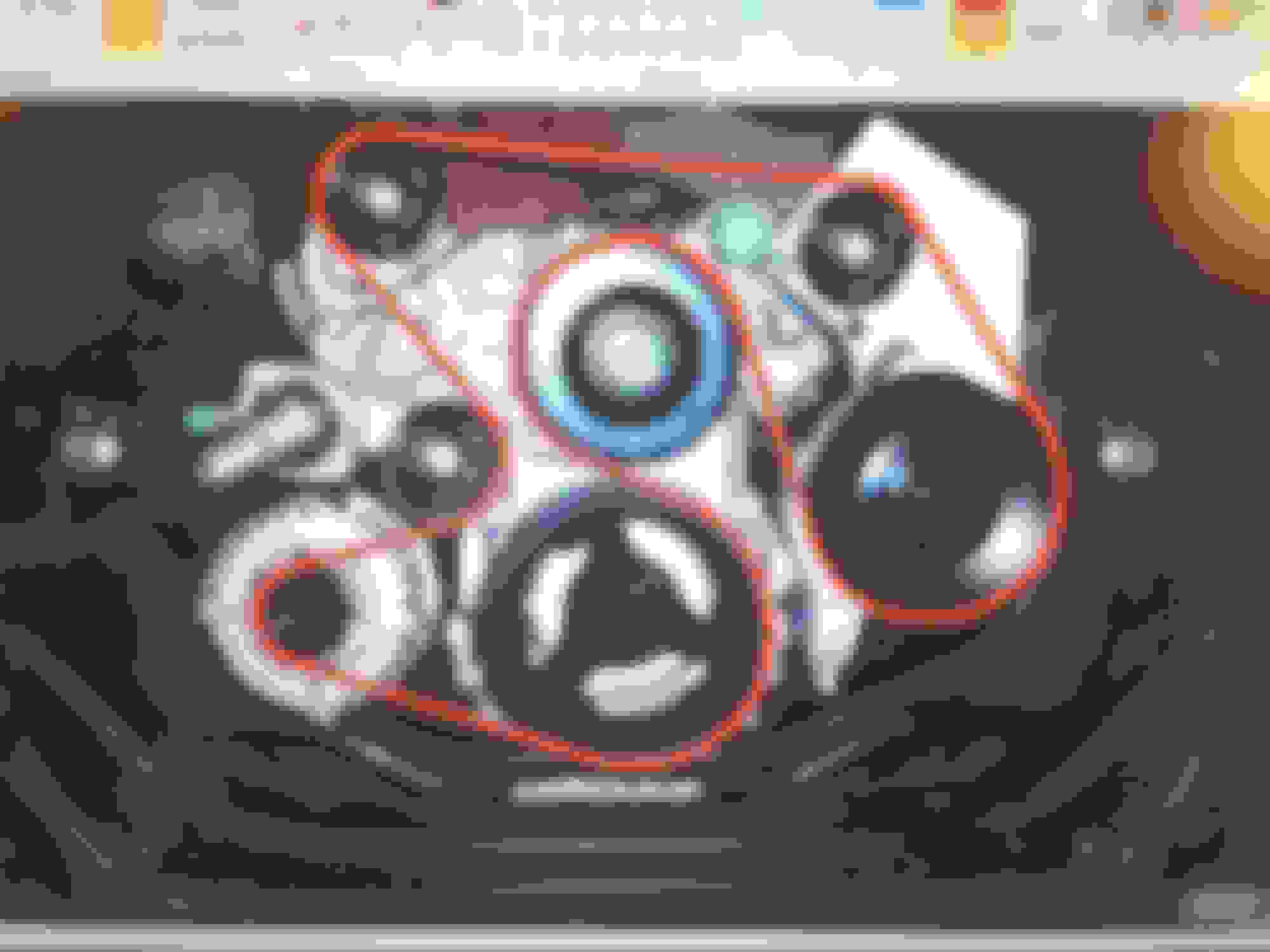
On the left side starting from the top are SS304 schedule 40 2.5" weld elbows, "long" and "short" bend radii at 2.5" and 3.75" CLR, respectively. These are 2.45" ID, 0.210" wall thickness, and about 2.89" OD.
On the right side starting from the top are: SS304 16ga 2.5" tube (2.369" ID, 0.065" wall), and long and short SS321 schedule 5 2.0" elbows, 3.0" and 2.0" bend radii, at 2.248" ID, 0.080" wall, 2.41" OD. After discovering the previous turbo pipe cracking, my hunch was confirmed that I simply won't be using any of this thin-wall stuff, but it was good to get just to inspect and decide in person.
Ideally everything would be thick wall SS321 to retain heat and material properties at high temp, but 321 is so hard to find in any stianless blend let alone schedule 40, and it would be crazy expensive for long radius 2.5" stuff... so SS304 it will be.
The cool thing about the schedule 40 2.5" stuff is the inside perimeter is almost identical to that of a T3 turbo flange. I think I will grind a taper into the T3 flanges (they're 1/2" thick) to transition from the round to rectangular a bit better, and fill in and smooth the corners where there are gaps. But overall I'm very surprised and happy to see how close the profile are as-is, because squishing the round 0.210"-thick elbow into a rectangular shape on the end would suck.
I think the winning combo will be a long radius elbow from the manifold, then a short section of straight pipe, into a short radius elbow going into the turbo. I looked the short radius elbow over long and hard and really don't think it'll be too sharp of a bend for entering the turbo.
The nice thing is that after I updated my exhaust flow calcs with actual measured flange and elbow dimensions, the exhaust velocity from the head exhaust ports all the way to the flange is almost dead-on consistent. The exhaust velocity would drop off quite a lot if I were to use a T4 inlet turbo (far right numbers).
And here's a mockup of the Precision 46mm wastegates I'll be using.. plenty of room to route things I think..

 10-22-2017, 07:11 PM


 If for some reason that's not an option, flattening or ovaling out a center pipe should take some of that elephant trunk look away. Or you could try moving to an oval throttle body and charge tube like what was used on the old LT1s and TPI engines. It would still be center trunk-like but not so much a round noodle.


 The inside of the carbon is very nice and smooth, and is about 0.085" wall thickness.