


Yet another, BMW E-36 LSx conversion...
Between doc visits, a trip out to Verona/Madison WI, (went the Packers-Bills game on the 19th and visited the EAA Air Venture museum while there), enrolling in some A-CAD classes, etc not much progress has been made on the car. There hasn�t been much to do any how as the headers are still being sorted out. 
I think my last substantial update was back in April or May? My how time flies watching grass grow. Once the headers get sorted and finally built, then it�ll be gangbusters to get it on the road, probably wont stop to update the build thread till it�s on the road and I can breathe again�
For now, just another pittly little update.
Started in on the wiring, reconfiguring pin out and inserting pins back in the circular BMW connectors I picked up for the ABS relocation, (just made and extension harness, didn't have to cut or splice the car or ABS module), in the middle of routing the LSx harness.
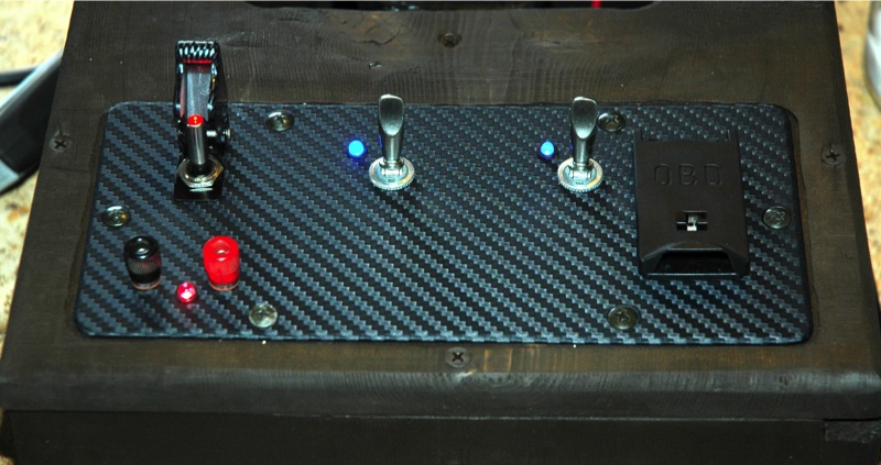
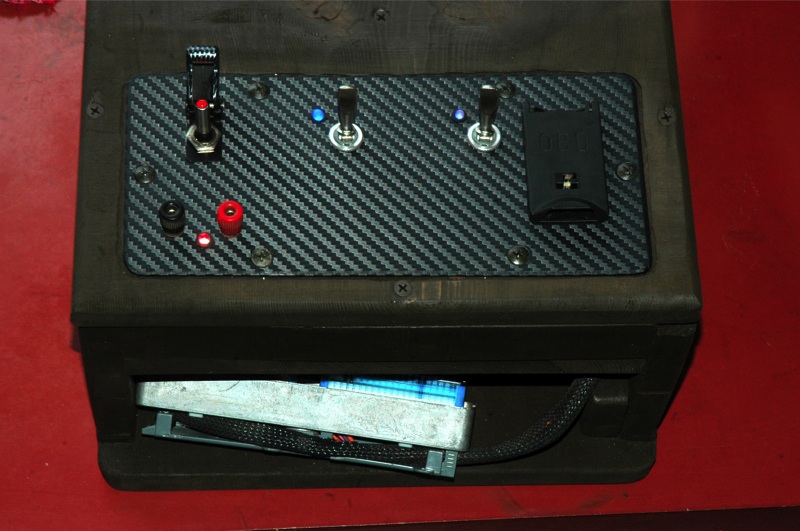
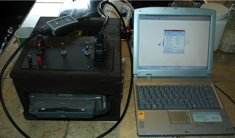
Thank you to Pzary for his advice I spent a couple days building a cheesy little PCM desktop tuning bench, now I can access and tune the PCM outside of the car, on the bench/desktop. Made a couple adjustments to the PCM tonight including Throttle Cracker, Throttle Follower, fuel cut parameters, will be massaging the VE table and ignition map to better match the Vette cam, etc. (PCM is '02 Avalanche), bench tuned a few others PCMs as well for other swappers, (delete VATS, skip shift, set tach signal, tire size/gearing, hi-lo speed cooling fan set points, etc).
PCM tuning bench extracting data;
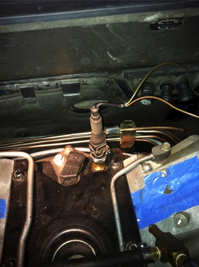
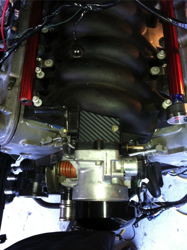
BMW Oil pressure sender is installed on the LSx. Spent more time scratching my head with hand full of fittings trying to figure out how I am going to do this. Almost just drilled and tapped the 16x1.5mm adapter to directly accept the 12x1.5mm oil pressure sender, but couldn�t quite bring myself to do that as the wall thickness would be quite thin and the last thing I want is to shear the head off the adapter leaving its threads in the block of an assembled engine. Using another 1/8 NPT fitting I drilled the female end and tapped for 12x1.5mm to accept the BMW oil pressure sender for the idiot light, robbed the LSx oil pressure sender crush gasket and installed the mess.
There has to be an oil pressure switch out here from another OE application that is 16x1.5 mm threads. Sure would make that a whole lot easier.
While watching the Grass grow I thought I�d play a little more with my 3M Di-NOC faux carbon fiber, (used it on the PCM tuning bench), and covered the aluminum plug cover for the EGR port on the LS1 intake. Don�t like the shiny screw head, may have to faux anodize that, black sharpie.

I think my last substantial update was back in April or May?
For now, just another pittly little update.
Started in on the wiring, reconfiguring pin out and inserting pins back in the circular BMW connectors I picked up for the ABS relocation, (just made and extension harness, didn't have to cut or splice the car or ABS module), in the middle of routing the LSx harness.
Thank you to Pzary for his advice I spent a couple days building a cheesy little PCM desktop tuning bench, now I can access and tune the PCM outside of the car, on the bench/desktop. Made a couple adjustments to the PCM tonight including Throttle Cracker, Throttle Follower, fuel cut parameters, will be massaging the VE table and ignition map to better match the Vette cam, etc. (PCM is '02 Avalanche), bench tuned a few others PCMs as well for other swappers, (delete VATS, skip shift, set tach signal, tire size/gearing, hi-lo speed cooling fan set points, etc).
PCM tuning bench extracting data;
BMW Oil pressure sender is installed on the LSx. Spent more time scratching my head with hand full of fittings trying to figure out how I am going to do this. Almost just drilled and tapped the 16x1.5mm adapter to directly accept the 12x1.5mm oil pressure sender, but couldn�t quite bring myself to do that as the wall thickness would be quite thin and the last thing I want is to shear the head off the adapter leaving its threads in the block of an assembled engine. Using another 1/8 NPT fitting I drilled the female end and tapped for 12x1.5mm to accept the BMW oil pressure sender for the idiot light, robbed the LSx oil pressure sender crush gasket and installed the mess.
There has to be an oil pressure switch out here from another OE application that is 16x1.5 mm threads. Sure would make that a whole lot easier.
While watching the Grass grow I thought I�d play a little more with my 3M Di-NOC faux carbon fiber, (used it on the PCM tuning bench), and covered the aluminum plug cover for the EGR port on the LS1 intake. Don�t like the shiny screw head, may have to faux anodize that, black sharpie.
Quick update and info on the GM Fuel tank pressure sensor.
Wiring is approx 95% complete, only couple connections to make, prime the oil system with the remote oil primer then fire it up.
In short, you must use the GM fuel tank pressure sensor with GM PCM to control the BMW evap canister vent and either the BMW or GM canister purge valve and you can NOT use a GM MAP sensor as fuel tank pressure sensor.
Specifics for us geeks;
Using and old PC power supply with its 5 volt DC power source I was able to test a GM fuel tank pressure sensor and the BMW fuel tank pressure sensor to see if the BMW sensor could be retained. In short, NO, it cannot be used with GM PCM. The BMW pressure sensor and GM fuel tank pressure sensor are reversed in their Voltage-to-pressure readings so it will not work properly. In using the GM PCM to control the evap canister and fuel tank purge valves, you must also use the GM fuel tank pressure sensor.
Also, you can NOT use a GM MAP sensor for this purpose. I have seen information on the net saying the GM MAP and GM Fuel Pressure sensor are the same, that is incorrect! Those claims are guesses, NOT tested or measured. After testing them side by side, (applying 5 volt and ground, measuring the signal while applying vacuum and pressure), they are not even close! They may look sort of similar, even have the same sealing grommet, but they are NOT the same nor interchangeable.
GM MAP sensors;
Testing the GM MAP sensors, my findings matched exactly what is found online. Registers atmospheric pressure and below i.e. vacuum. At atmospheric pressure, (WOT or engine off), voltage is 5 volt. Pull 5" of vacuum on the MAP sensor and the voltage drops to 4v. Pull another 5", (10" of vacuum total), voltage drops to 3 v. Pull another 5", (15" total), voltage drops to 2v. Pull another 5" of vacuum, (20" inches of vacuum total) and the voltage drops to 1v.
GM Fuel tank pressure sensor;
The fuel tank pressure sensor visually looks sort of similar to the MAP, has the same silicone sealing grommet but the MAP connector will not fit. For what it's worth, the crank position and Cam position sensor connector does fit the fuel tank pressure sensor. This sensor also registers pressure above atmospheric, but only barely and is MUCH more sensitive registering minute pressures below and above atmospheric i.e. vacuum and pressure. Of greater importance is its voltage to pressure values are reverse of the MAP sensor.
At atmospheric pressure, the fuel tank pressure sensor delivers 1.5 volts. As vacuum is applied, voltage rise is linear to 5 volts at approx. 1� or 2" of vacuum. My vacuum gauge is not accurate enough at that low of vacuum for an accurate measurement. Using your mouth you can easily max out the sensor with light suction or light pressure. Blow into it the voltage continues to drop below 1.5 down to minimum of .23v, I guess that to be pressure to be approx. 1-2 inches of pressure, not even half a PSI. Just blowing across the opening the voltage swings, this sensor is very sensitive.
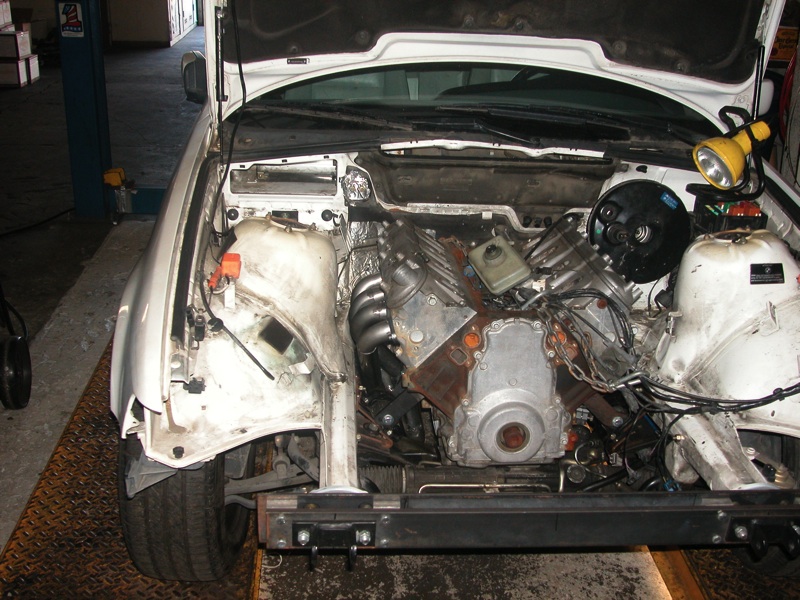
Short version, fired up the engine today! WOOHOO! 


Long version.
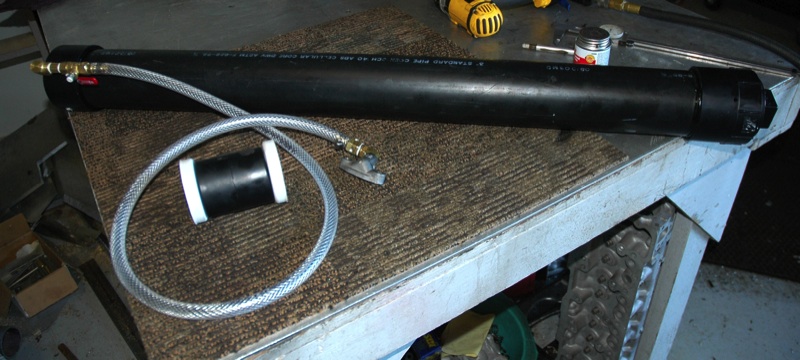
Built a DIY LSx engine oil primer, (air actuated piston forces 4 qt�s of fresh oil in to the engine oil galleys via the port above the oil filter), worked out perfect pressurizing the oil galleys with fresh oil, as well back filling to the pump. Just cranking the engine over on the starter with the coils/injectors disabled works fine, I wanted fresh oil to the bearing before spinning the crank.
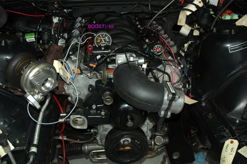
After a few electrical checks to verify wring was correct, no back feeds were going to keep the start engaged, pressurized the fuel system, etc. Then bumped the starter and the engine immediately came to life on all 8 cylinders, WOO HOO!
Here are some pics of the oil system primer and video of the start up.
Flames!
http://www.youtube.com/watch?v=hSnn9ZV1dmI
As a gag we clamped an old dead Turbo onto one of the exhaust Mani�s, it would barely spin, (boost gauge sitting on the intake)
http://www.youtube.com/watch?v=x73R-n9-6vQ
Long version.
Built a DIY LSx engine oil primer, (air actuated piston forces 4 qt�s of fresh oil in to the engine oil galleys via the port above the oil filter), worked out perfect pressurizing the oil galleys with fresh oil, as well back filling to the pump. Just cranking the engine over on the starter with the coils/injectors disabled works fine, I wanted fresh oil to the bearing before spinning the crank.
After a few electrical checks to verify wring was correct, no back feeds were going to keep the start engaged, pressurized the fuel system, etc. Then bumped the starter and the engine immediately came to life on all 8 cylinders, WOO HOO!
Here are some pics of the oil system primer and video of the start up.
Flames!
http://www.youtube.com/watch?v=hSnn9ZV1dmI
As a gag we clamped an old dead Turbo onto one of the exhaust Mani�s, it would barely spin, (boost gauge sitting on the intake)
http://www.youtube.com/watch?v=x73R-n9-6vQ
Update with wonderful news. 
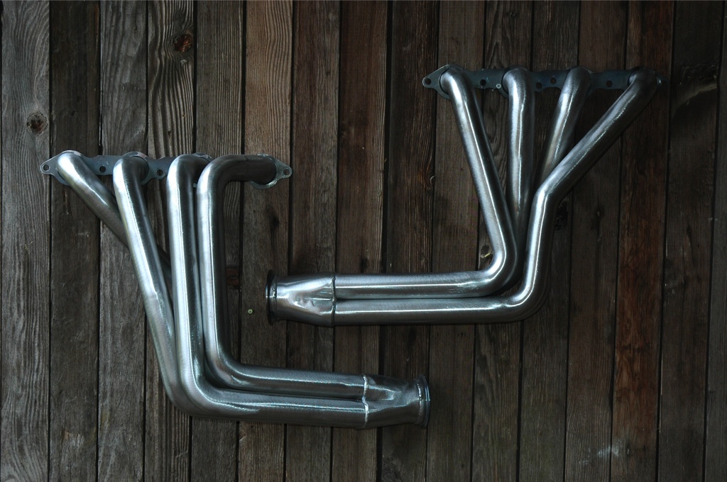
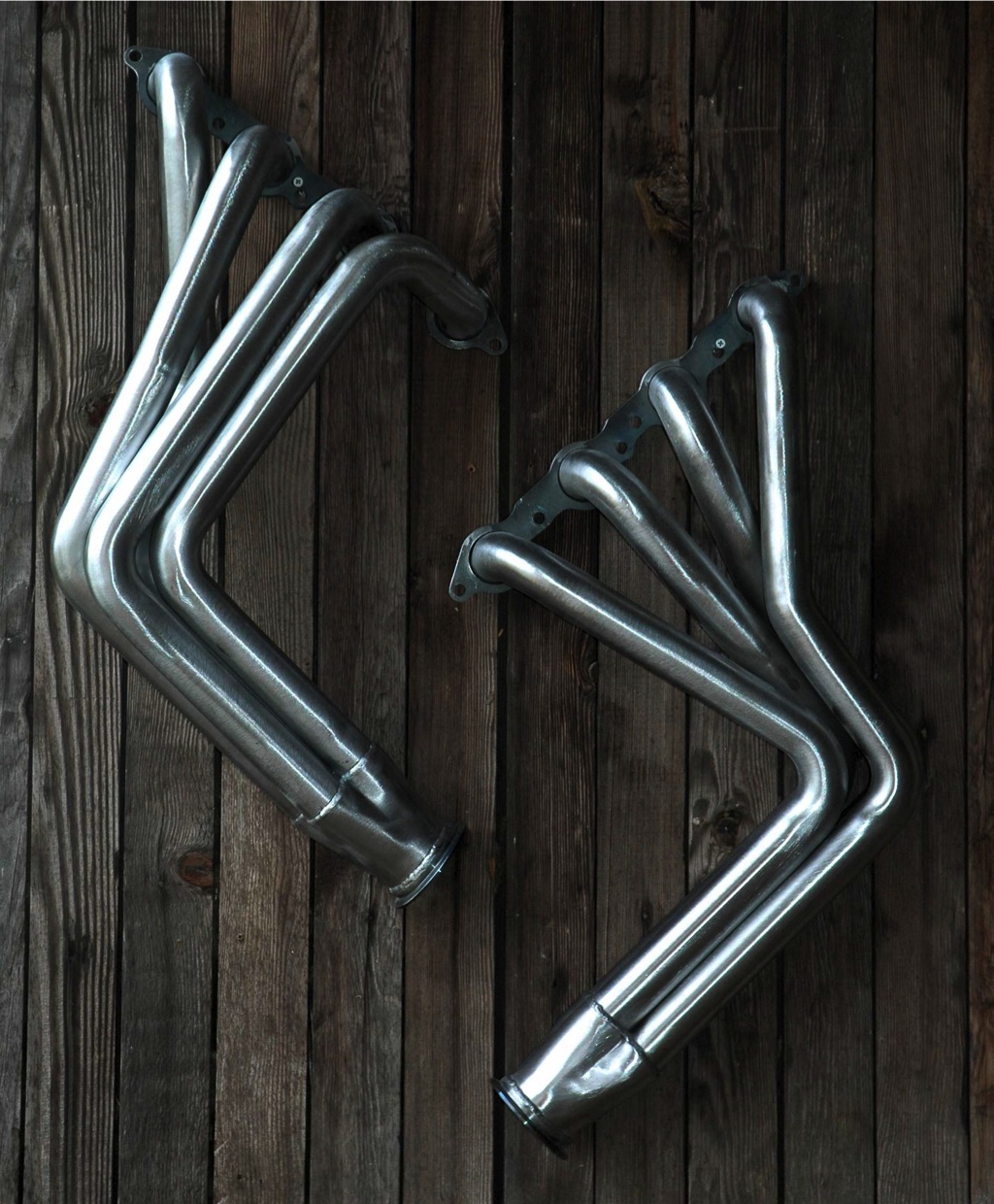
JTR and Sanderson Headers are getting close to releasing their E36 LSx long tube headers. Approx ETA for release of production units is 2-3 months.
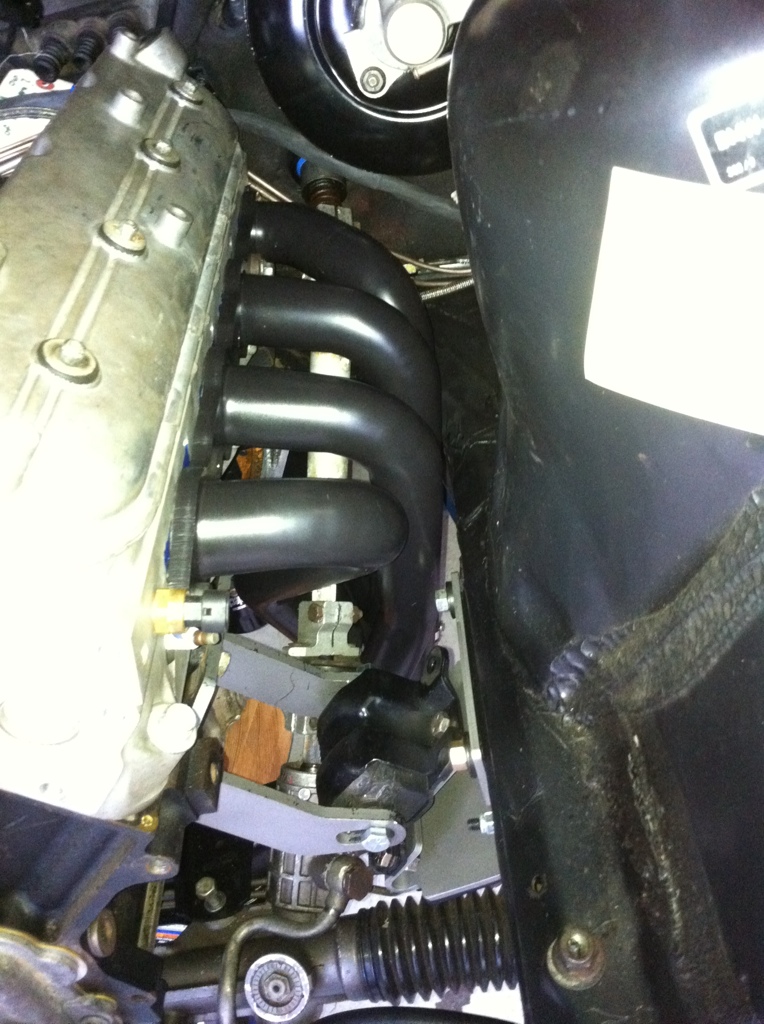
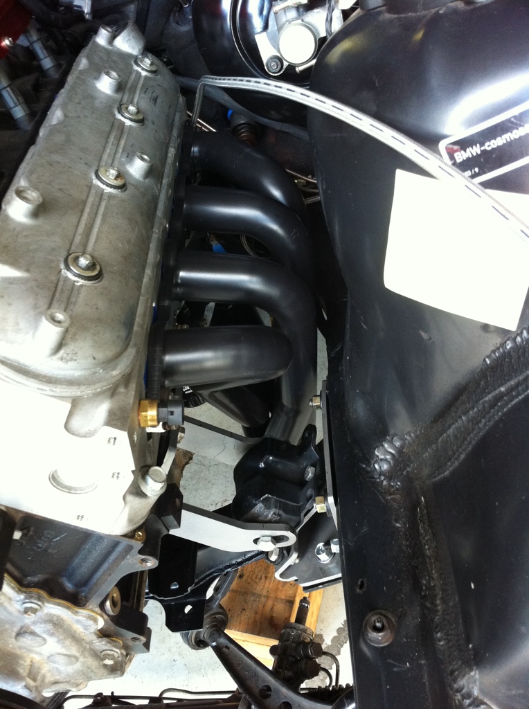
These pictures are of the Prototypes. Steel, long tube, 1 3/4" primaries, 3" collector, V-band connection, and they clear the stock steering shaft.
These prototypes have been given the green light from which Sanderson will build fixtures/jigs around for production units. Before any headers will be offered to the public a few pre-production units must also receive the green light from JTR, (quality assurance), once the pre production units pass, production will start. Again, earliest release of approx 2 months time so long as the preproduction units fit as intended.
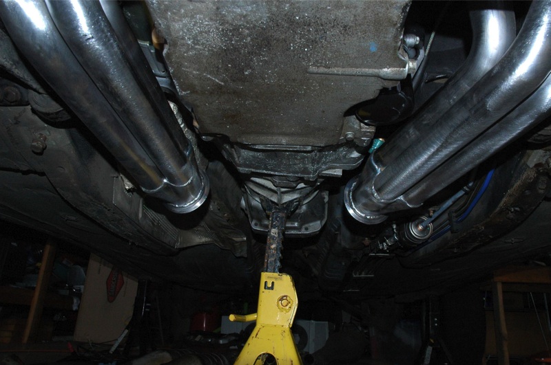
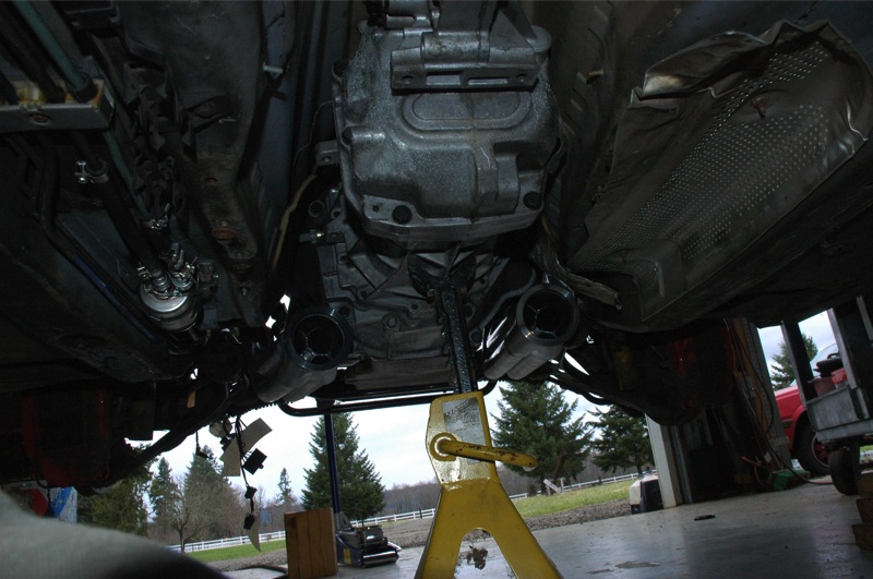
Pics of the JTR mockup mule at Sanderson Headers.
Driver side;
Passenger side;

JTR and Sanderson Headers are getting close to releasing their E36 LSx long tube headers. Approx ETA for release of production units is 2-3 months.
These pictures are of the Prototypes. Steel, long tube, 1 3/4" primaries, 3" collector, V-band connection, and they clear the stock steering shaft.
These prototypes have been given the green light from which Sanderson will build fixtures/jigs around for production units. Before any headers will be offered to the public a few pre-production units must also receive the green light from JTR, (quality assurance), once the pre production units pass, production will start. Again, earliest release of approx 2 months time so long as the preproduction units fit as intended.
Pics of the JTR mockup mule at Sanderson Headers.
Driver side;
Passenger side;
JTR BMW-LSx conversion kit
Most aspects of the kit have been sorted and prototype bits built, only few little details to sort out. Headers are the last big hurdle.
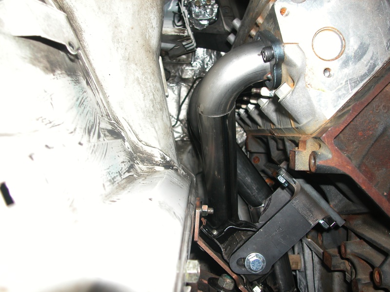
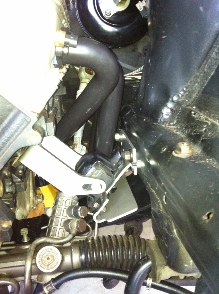
Here is the driver side mount, ties the X-member to the frame rail, uses OE GM captured isolators available in varying stiffnesses, allows for slight adjustably fore-aft, left-right, up-down.


Final mount the engine-trans once the headers arrive, tie the stock M3 exhaust to the headers, route heater hoses and heater valve, coolant hoses, put the front end back together, final pass of electical and fluid line checks and any other loose ends. I figure 1 month to 2 months to be on the road once the headers arrive.
LS1 Tech Stories
The Best V8 Stories One Small Block at Time

6 Common C5 Corvette Failures and What's Involved In Repairing Them
Pouria Savadkouei
Retro Modern Bandit Pontiac Trans AM Comes With Burt Reynolds' Autograph
Verdad Gallardo
Top 10 Greatest Cadillac V Series Performance Models Ever, Ranked
Pouria Savadkouei
Top 10 Most Powerful Chevy Trucks Ever Made!

Hennessey's New Supercharged Silverado ZR2 Has 700 HP
Verdad Gallardo
Coachbuilt N2A Anteros Is an LS2-Powered C6 Corvette In Italian Clothes
Verdad Gallardo
Awesome K5 Blazer Restomod Comes With C7 Corvette Power
Verdad Gallardo
10 Camaros You Should Never Buy

10 LS Engine Myths That Refuse to Die
Verdad Gallardo Just read the the build and all I can say is wow. I wish I had the knowledge and skill to pull this off on my own. Props on going with a 4dr E36. Nothing like cruising with 4 other people with a lsx under the hood. Plus the car will still handle great too.
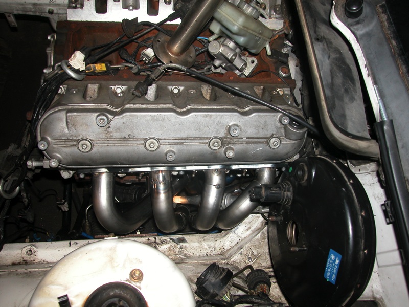
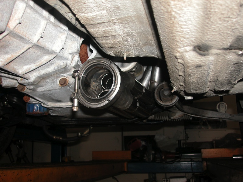
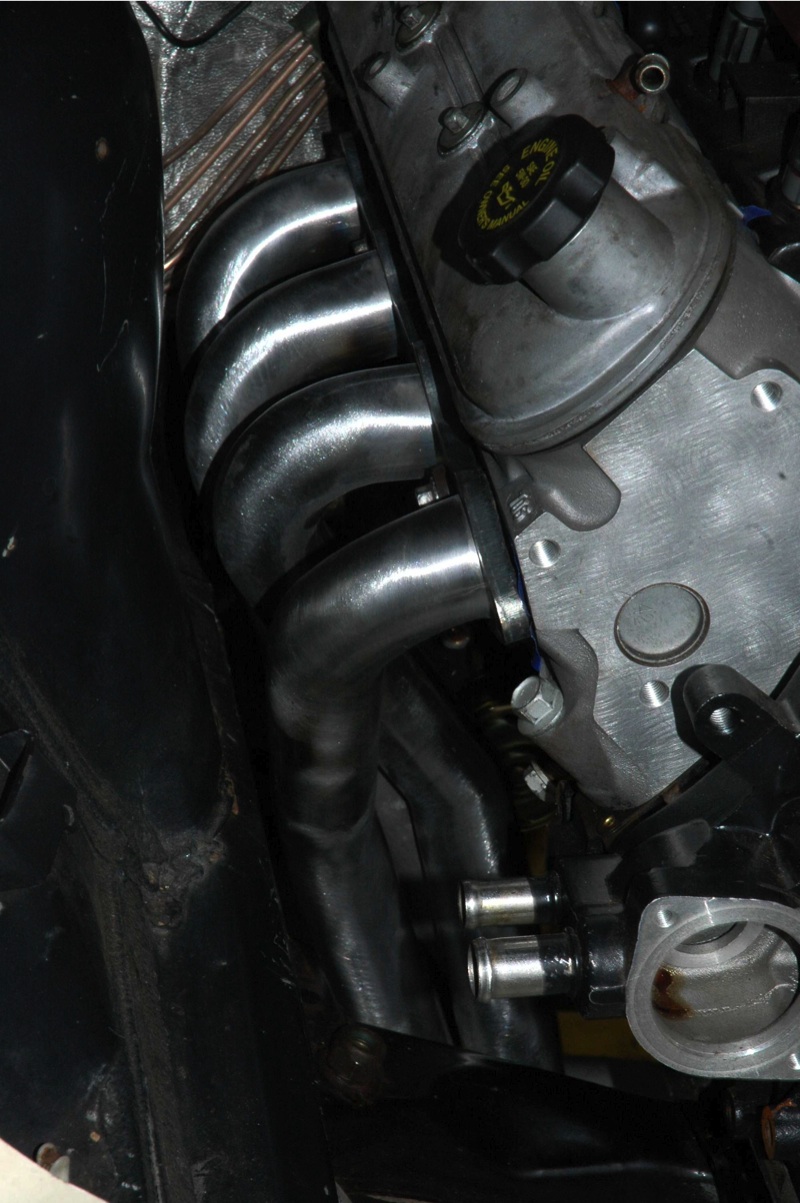
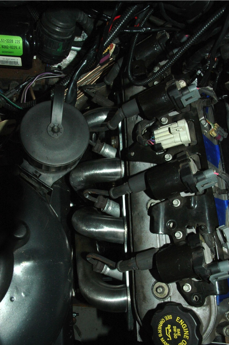
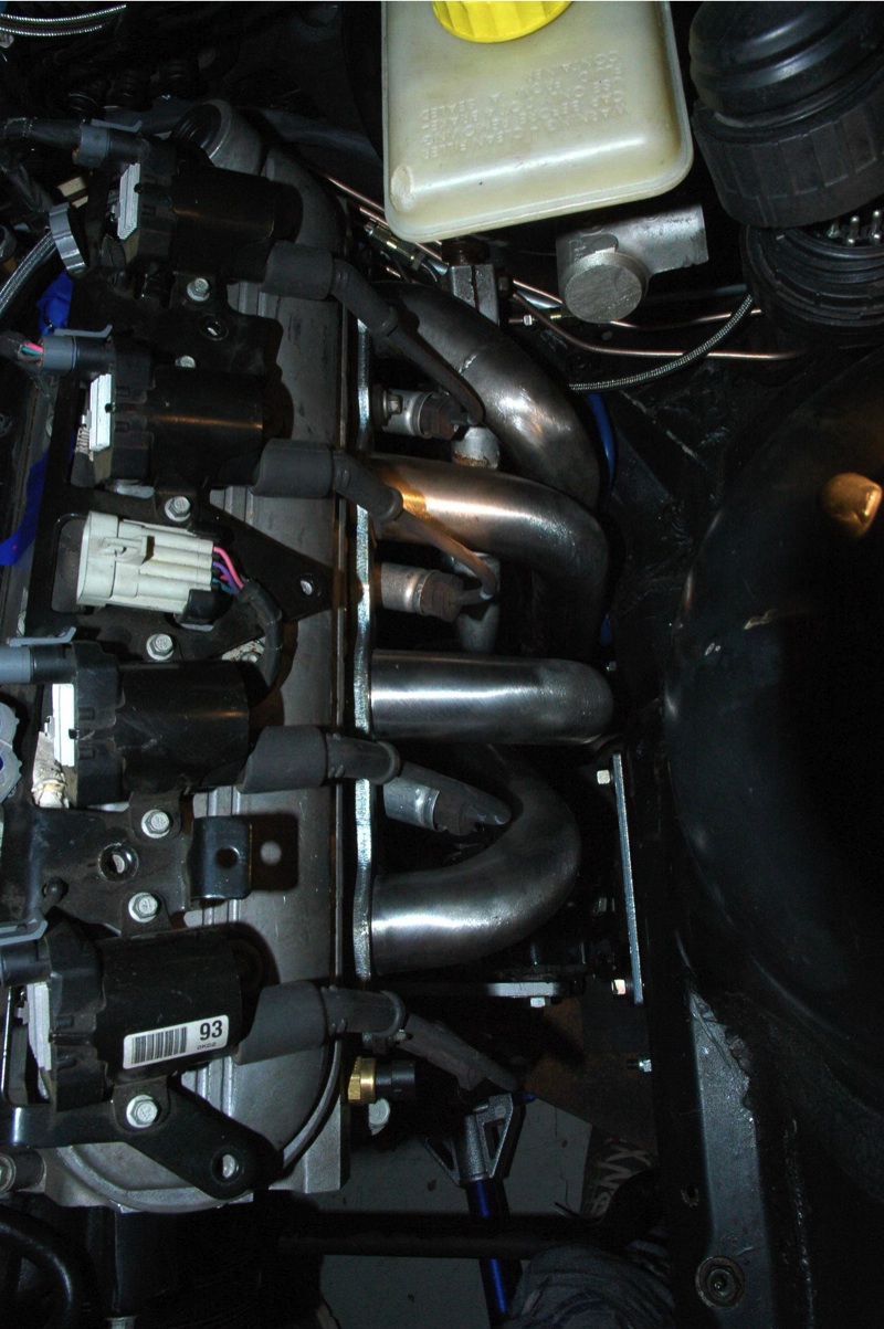
Headers arrived, excellent quality and fit very well. 1 3/4" long tube mild steel, 3� V-band flange.
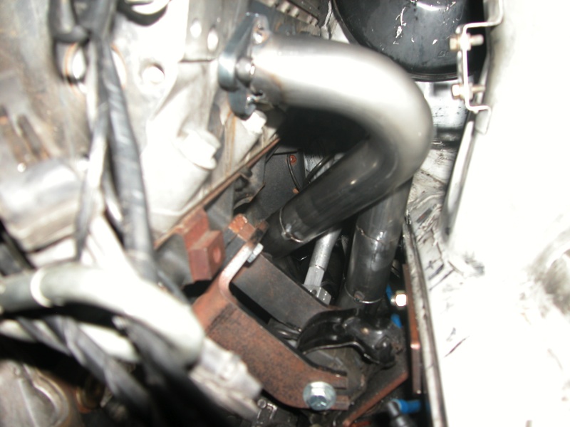
Excellent clearance between the #7 primary and Mercedes booster as well as the stock BMW steering shaft. Taking them down to Finish-line coatings here in Portland on Monday for their Turbo-Black ceramic.
Now with headers here, mounts can be finalized, trans X-member designed and built around the GM F-bod LS1 trans isolator, heater hose/pipe routed, final fuel line routing into the engine bay, etc.
Here are some shots of the soon to be released JTR E36 LSx long tube mild steel headers.


Sorry for the lack of updates on this forum, family issues have distracted me. I still have it, almost on the road.
Here are the updates Since January.
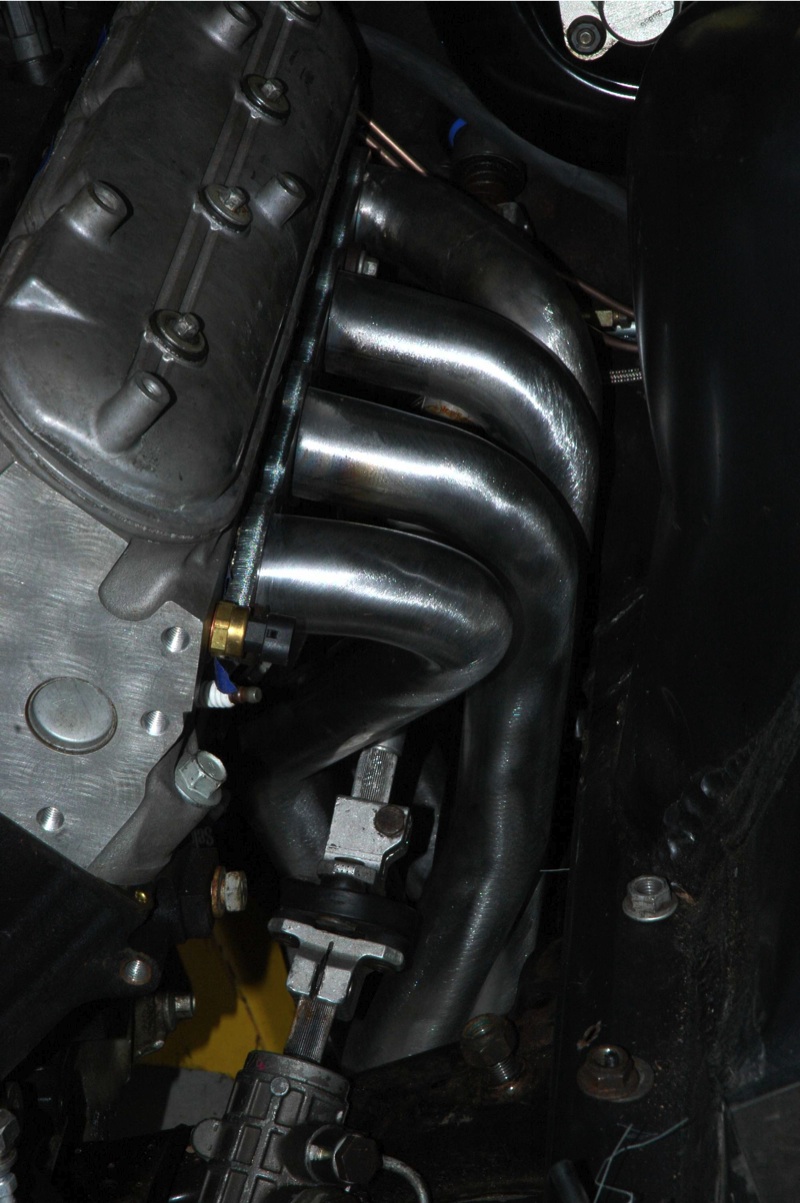
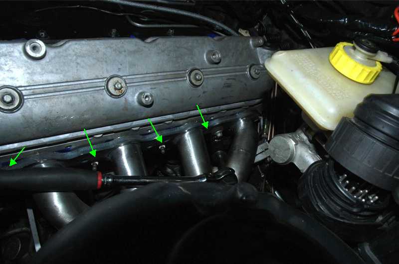
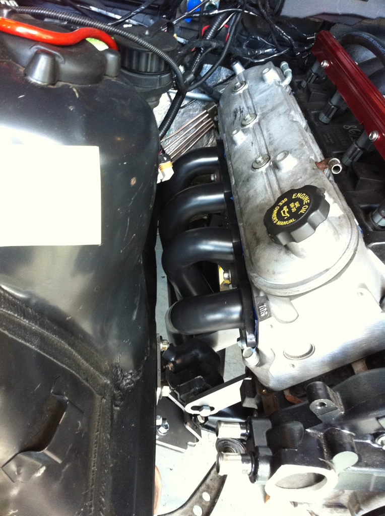
One of the criteria I hoped for in the design was adequate spark plug access and plug wire clearance, Sanderson/JTR came through. Access to all 8 spark plugs is excellent! A Ratchet, spark-bolt socket, and a 3" extension accesses all spark plugs nicely. #7 is better reached with a wobbly added, but can be accessed without if desperate.
Mocked up the coils with a set of factory GM truck plug wires with the metal shield around the plug boot, those also fit on all 8 plugs. #7 primary is close to the rubber portion protruding out the top of shield, a little creative trimming might be enough.
Here are the updates Since January.
One of the criteria I hoped for in the design was adequate spark plug access and plug wire clearance, Sanderson/JTR came through.
Access to all 8 spark plugs is excellent! A Ratchet, spark-bolt socket, and a 3" extension accesses all spark plugs nicely. #7 is better reached with a wobbly added, but can be accessed without if desperate. Mocked up the coils with a set of factory GM truck plug wires with the metal shield around the plug boot, those also fit on all 8 plugs. #7 primary is close to the rubber portion protruding out the top of shield, a little creative trimming might be enough.
Quick update sorry for crappy phone pics. Took some real pics, hope to get those posted early next week.
Any how, got the JTR headers back from Finishline Coatings here in Portland. This is the Best thermal coating they offer, they claim it is a 60% reduction of heat vs uncoated. They applied 2 coats externally, 1 coat internally. Personally, I really like matte black finish, should contrast nice with the wrinkle black valve covers that will go on after the engine is installed for the last time.
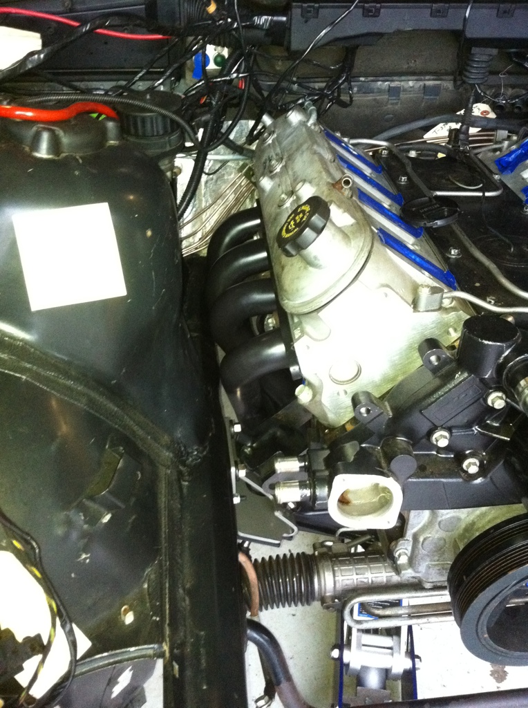
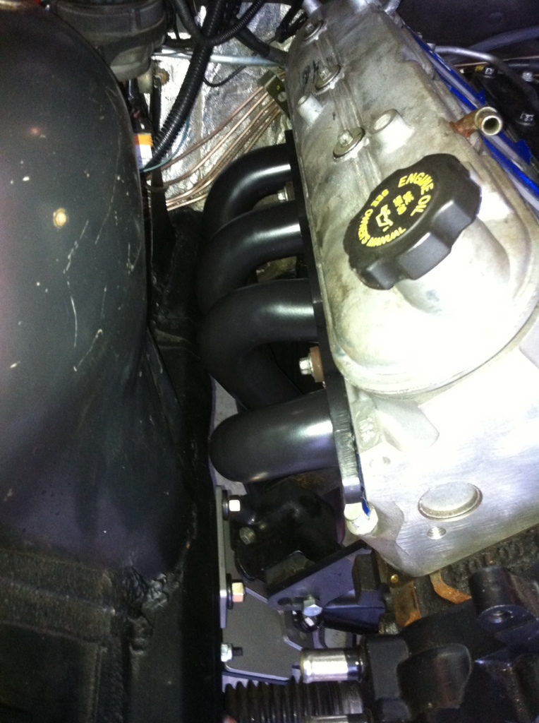
Any how, got the JTR headers back from Finishline Coatings here in Portland. This is the Best thermal coating they offer, they claim it is a 60% reduction of heat vs uncoated. They applied 2 coats externally, 1 coat internally. Personally, I really like matte black finish, should contrast nice with the wrinkle black valve covers that will go on after the engine is installed for the last time.
Sorry for the lack of updates. Family issues among other things have taken priority.
Recently was able to get back to making progress, working on the heater hoses currently, trans X-member is on the way, stay tuned. :alright
For now a couple more shots of the JTR headers in Turbo-Black ceramic coating and the JTR LSx E-36 engine mounts.

Recently was able to get back to making progress, working on the heater hoses currently, trans X-member is on the way, stay tuned. :alright
For now a couple more shots of the JTR headers in Turbo-Black ceramic coating and the JTR LSx E-36 engine mounts.
Small update.*
Made some headway this past week and weekend. Heater hoses are now done, brake booster vacuum line is done, brakes are 100% and bled.*
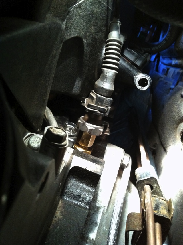
Relocated the heater valve to just under and in front of the brake M/C. I used the BMW mount that was attached to the wall and attached it to the driver fenderwell as high as possible next to the strut tower. Heater supply hose (5/8"hose off the water water pump) routed down and then under the engine above the rack and pinion up to the bottom/middle port of the valve with a 5/8"-3/4" reducer 180 bend. The other 2 lines from the valve are routed to the firewall under the brake M/C. Heater return line is the only hose routed behind intake manifold. I don't know how you other guys are able to get 3 hoses behind there when 1 hose barely fits.*
Fired up my DIY brake pressure bleeder with a converted Mercedes reservoir cap, (BMW & Merc caps are the same size and threads), hooked up shop air, regulated down to 7 PSI and pumped just over 2 qts of DOT4 through the system and ABS module purging all the old dark fluid from the car. Hooked up the electric vacuum pump to the brake booster simulating a running engine, pedal feels good. ;-)
The only other item to address while waiting the trans X-member is the PCV plumbing. :-(
Once the trans X-member arrives, tie the headers to the exhaust, detail the shifter and boot, radiator and hoses, and God willing be driving it, soon.*
Made some headway this past week and weekend. Heater hoses are now done, brake booster vacuum line is done, brakes are 100% and bled.*
Relocated the heater valve to just under and in front of the brake M/C. I used the BMW mount that was attached to the wall and attached it to the driver fenderwell as high as possible next to the strut tower. Heater supply hose (5/8"hose off the water water pump) routed down and then under the engine above the rack and pinion up to the bottom/middle port of the valve with a 5/8"-3/4" reducer 180 bend. The other 2 lines from the valve are routed to the firewall under the brake M/C. Heater return line is the only hose routed behind intake manifold. I don't know how you other guys are able to get 3 hoses behind there when 1 hose barely fits.*
Fired up my DIY brake pressure bleeder with a converted Mercedes reservoir cap, (BMW & Merc caps are the same size and threads), hooked up shop air, regulated down to 7 PSI and pumped just over 2 qts of DOT4 through the system and ABS module purging all the old dark fluid from the car. Hooked up the electric vacuum pump to the brake booster simulating a running engine, pedal feels good. ;-)
The only other item to address while waiting the trans X-member is the PCV plumbing. :-(
Once the trans X-member arrives, tie the headers to the exhaust, detail the shifter and boot, radiator and hoses, and God willing be driving it, soon.*