


Need help with LS2 DBW
Im putting a T-56 into a '08 TBSS. I'm running the motor stand alone using a 07 CTS-V ECM. The TBSS ECM is running the guages etc. It starts and runs, and all my guages work, but I cannot get the throttle to work.
Here are the DTCs that I get.
[ECM] P0315 - Crankshaft Position System Variation Not Learned (SES) (Pending) (Old) (History) (Current) (Immature)
[ECM] P060D - Internal Control Module Accelerator Pedal Position Performance (SES) (Pending) (History) (Current) (Immature)
[ECM] P2119 - Throttle Actuator Control Throttle Body Range/Performance (Pending) (Old) (History) (Current) (Immature)
[ECM] P2138 - Throttle/Pedal Position Sensor/Switch D/E Voltage Correlation (SES) (Pending) (History) (Current) (Immature)
[ECM] P0315 - Crankshaft Position System Variation Not Learned
[ECM] P060D - Internal Control Module Accelerator Pedal Position Performance
[ECM] P2138 - Throttle/Pedal Position Sensor/Switch D/E Voltage Correlation
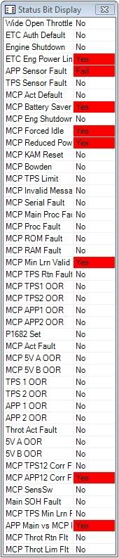
I also scanned it with status bits and got this:
The accelerator pedal is a brand new from GM, 07 CTS-V pedal. I had to swap pins A and C at the APP connector to match the pinout for the CTS-V pedal. I verified that both 5v and low refs are good at the APP connector.
Here is the GM description for the APP on a 07 CTS-V:
The APP sensors are used to determine the pedal angle. The engine control module (ECM) provides each APP sensor a 5-volt reference circuit and a low reference circuit. The APP sensors provide the ECM with signal voltage proportional to the pedal movement. The APP sensor 1 signal voltage at rest position is less than 1 volt and increases to above 4 volts as the pedal is actuated. The APP sensor 2 signal voltage at rest position is near 0.5 volt and increases to more than 2 volts as the pedal is actuated.
I tested for voltage on the two APP signal wires using two different methods..
The first time I tested, I removed the signal wire that was being tested from the ecm connetor, put the positve probe to that wire, and then put the negative probe to the negative battery terminal. The results were dead on with the GM description above.
The second time I removed the signal wire from the connector, and then inserted a short piece of wire (terminal on one end and bare wire on the other end) into the ECM connector in the same location that the signal wire was removed from. I put the positive probe on the signal wire coming from the pedal and I put the negative probe on the short piece of wire going into the ecm. This way it uses the ground through the ECM and doesnt bypass it by going straight to the battery. The voltages would never steady out on the 2nd method, they were always fluctuating just slightly.
Here are the results:
1st Test (Spot on with the GM description)
APP 1 - Rest = 0.974v
APP 1 - Floored = 4.13v
APP 2 - Rest = 0.489v
APP 2 - Floored = 2.051v
2nd Test
APP 1 - Rest = 0.787v
APP 1 - Floored = 3.2v
APP 2 - Rest = 0.331v
APP 2 - Floored = 1.42v
I also scanned for TPS% and at rest (spring loaded position) it shows 33%, at fully closed it shows 15%, and at fully open it shows 89%.
At this point I think I have a bad ECM but wanted to get some opinions before I go buy another one.
Thanks!!!
Here are the DTCs that I get.
[ECM] P0315 - Crankshaft Position System Variation Not Learned (SES) (Pending) (Old) (History) (Current) (Immature)
[ECM] P060D - Internal Control Module Accelerator Pedal Position Performance (SES) (Pending) (History) (Current) (Immature)
[ECM] P2119 - Throttle Actuator Control Throttle Body Range/Performance (Pending) (Old) (History) (Current) (Immature)
[ECM] P2138 - Throttle/Pedal Position Sensor/Switch D/E Voltage Correlation (SES) (Pending) (History) (Current) (Immature)
[ECM] P0315 - Crankshaft Position System Variation Not Learned
[ECM] P060D - Internal Control Module Accelerator Pedal Position Performance
[ECM] P2138 - Throttle/Pedal Position Sensor/Switch D/E Voltage Correlation
I also scanned it with status bits and got this:
The accelerator pedal is a brand new from GM, 07 CTS-V pedal. I had to swap pins A and C at the APP connector to match the pinout for the CTS-V pedal. I verified that both 5v and low refs are good at the APP connector.
Here is the GM description for the APP on a 07 CTS-V:
The APP sensors are used to determine the pedal angle. The engine control module (ECM) provides each APP sensor a 5-volt reference circuit and a low reference circuit. The APP sensors provide the ECM with signal voltage proportional to the pedal movement. The APP sensor 1 signal voltage at rest position is less than 1 volt and increases to above 4 volts as the pedal is actuated. The APP sensor 2 signal voltage at rest position is near 0.5 volt and increases to more than 2 volts as the pedal is actuated.
I tested for voltage on the two APP signal wires using two different methods..
The first time I tested, I removed the signal wire that was being tested from the ecm connetor, put the positve probe to that wire, and then put the negative probe to the negative battery terminal. The results were dead on with the GM description above.
The second time I removed the signal wire from the connector, and then inserted a short piece of wire (terminal on one end and bare wire on the other end) into the ECM connector in the same location that the signal wire was removed from. I put the positive probe on the signal wire coming from the pedal and I put the negative probe on the short piece of wire going into the ecm. This way it uses the ground through the ECM and doesnt bypass it by going straight to the battery. The voltages would never steady out on the 2nd method, they were always fluctuating just slightly.
Here are the results:
1st Test (Spot on with the GM description)
APP 1 - Rest = 0.974v
APP 1 - Floored = 4.13v
APP 2 - Rest = 0.489v
APP 2 - Floored = 2.051v
2nd Test
APP 1 - Rest = 0.787v
APP 1 - Floored = 3.2v
APP 2 - Rest = 0.331v
APP 2 - Floored = 1.42v
I also scanned for TPS% and at rest (spring loaded position) it shows 33%, at fully closed it shows 15%, and at fully open it shows 89%.
At this point I think I have a bad ECM but wanted to get some opinions before I go buy another one.
Thanks!!!
On The Tree
Joined: Jul 2006
Posts: 143
Likes: 0
From: great white northeast
ECM operating system, pedal, throttle body must be matched.
I believe the pedal from the CTS and the TBSS are different and so are the throttle bodies.
I went through this last year with GTO, TBSS mix and match stuff.
I ended up buying a GTO pedal to match the throttle body and re-flashing the ECM to a GTO serial #
Good luck
I believe the pedal from the CTS and the TBSS are different and so are the throttle bodies.
I went through this last year with GTO, TBSS mix and match stuff.
I ended up buying a GTO pedal to match the throttle body and re-flashing the ECM to a GTO serial #
Good luck
The above isnt necessarily true. I have and LS7 E38 ECM, with and LS2 throttle body and and cobalt pedal. I initially had a TBSS throttle body and was popping codes, not the same codes as above though. I first thought it was the pedal, but the LS2 TB fixed it.
Have you tried putting the pins back to where they originally were? I though all the pedal pinouts where the same.
Have you tried putting the pins back to where they originally were? I though all the pedal pinouts where the same.
A lot of the TBSS guys are running the LS7 TB so they should interchange.
Trending Topics
Hmmm...The LS2 throttle body is the same as the LS3/7 so I dunno what's up with that...Especially since the computer is programmed for the CTS-V pedal assembly...There are guys over on Performance trucks swapping their truck tbs for the LS2/3/7 style thinking it will add HP without any problems though...
LS1 Tech Stories
The Best V8 Stories One Small Block at Time

Topdon ONE vs. Artidiag 800 BT2: Which is the Diagnostic Tablet For You?
Pouria Savadkouei
Gas Monkey Built a 6-Wheel Ferrari Testarossa With a Corvette LT4 Engine
Verdad Gallardo
7 Most Reliable High-Performance Engines GM Has Ever Built
Verdad Gallardo
Amazing '71 Camaro Restomod Is Modern Muscle Car Under the Skin
Verdad Gallardo
6 Common C5 Corvette Failures and What's Involved In Repairing Them
Pouria Savadkouei
Retro Modern Bandit Pontiac Trans AM Comes With Burt Reynolds' Autograph
Verdad Gallardo
Top 10 Greatest Cadillac V Series Performance Models Ever, Ranked
Pouria Savadkouei
Top 10 Most Powerful Chevy Trucks Ever Made!

Hennessey's New Supercharged Silverado ZR2 Has 700 HP
Verdad Gallardo Lets get this straight.
Vehicle-2008 TBSS
Engine-2008 TBSS LS2
ECM-2008 TBSS E-??
You mention you also have a CTS-V ECM, assuming an E-38? Do you have 2 ECM's in the car?
I don't understand where the CTS-V ECM comes into play. Why did you set it up this way?
Vehicle-2008 TBSS
Engine-2008 TBSS LS2
ECM-2008 TBSS E-??
You mention you also have a CTS-V ECM, assuming an E-38? Do you have 2 ECM's in the car?
I don't understand where the CTS-V ECM comes into play. Why did you set it up this way?
The TBSS ECM will not work with a manual trans. The TBSS tune will not recognize a clutch pedal position signal, cannot control the reverse lockout solenoid, and requires the tcm to get a speedo signal. The raw AC voltage from the VSS goes to the tcm, the tcm compares that voltage with the iss signal, and then sends a buffered signal out to the ecm, which in turn generates a 4000 pulse per mile signal and sends that out to your ipc. The '07 CTS-V tune is designed to accept the raw AC voltage straight from the vss (since there is no TCM or ISS) and generates the 4000 pulse per mile signal to send out to your ipc.

Staging Lane
Joined: Jun 2007
Posts: 51
Likes: 0
I am just finishing a 2007 LS2/ 4L70 E From a Trailblazer SS . installation in a 1967 Nova . I Could not get the GM Performance wiring /E67 package to communicate with the Trans T42.Engine ran great though . Just trans issues. So I an had an extra E67 programmed at Vector to a trailblazer SS Tune.and no throttle. we determined the wiring was different like you said , we switched the wires still no response. so I bought a trailbalzer throttle pedal returned the wires to the trail blazer type , then the throttle would work. next we set MAF codes then found the wiring pinouts different on my GM performance Cadillac CTSV Programmed harness different thee another Corvette (2008) that was in there shop . we switched the pins to that arrangement and it started and ran fine then they could do their tune. Car runs great made 341 road horse . However still trying to get into the T42 .A stock TB SS T42 will not even let the trans shift.

Not sure that your problem will be the same as mine was, but I was initially running the engine without the drivebelt attached. As soon as the pcm saw no voltage from alternator, my pedal wouldn't work.
Hooked up the belt and it works perfect now.
Hooked up the belt and it works perfect now.