
Project PT-57, 1957 Chevy Pickup C5/C6 Corvette Suspension

 07-04-2011, 02:41 PM
#42
Launching!
Thread Starter
Join Date: Jan 2007
Location: Luling TX In the Hot Rod Shop
Posts: 294
Likes: 0
Received 3 Likes
on
3 Posts

So you might ask what’s been going on with the PT-57 and why has Russell stopped posting information. We’ll, we’re still in business after this last year. Its been interesting and that’s taken up too much of my time just in the day to day operations. We’ve gotten more models of the C6 parts and I’ve spent a large amount of time turning them into manageable files groups we’re I can adjust the suspension geometry in the computer depending on what car we’re working on. Lots of time consuming BS for a 2 man shop but it’s all necessary and we’re still in business. I think that saying a lot these days.
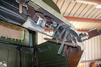
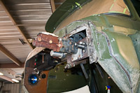
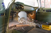
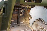
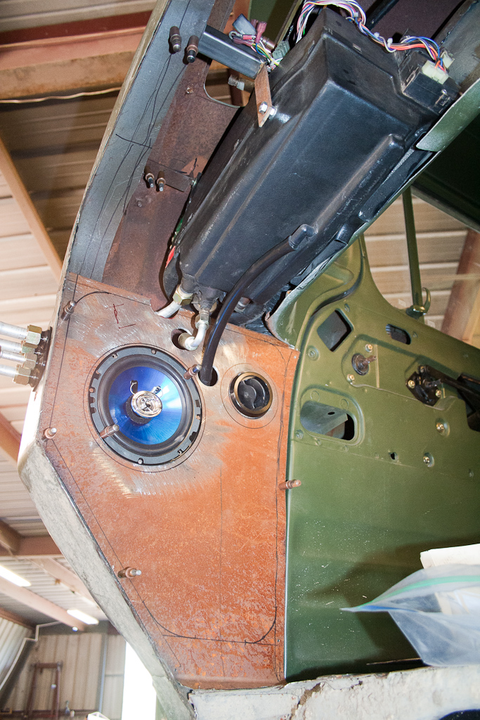
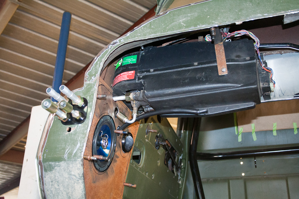
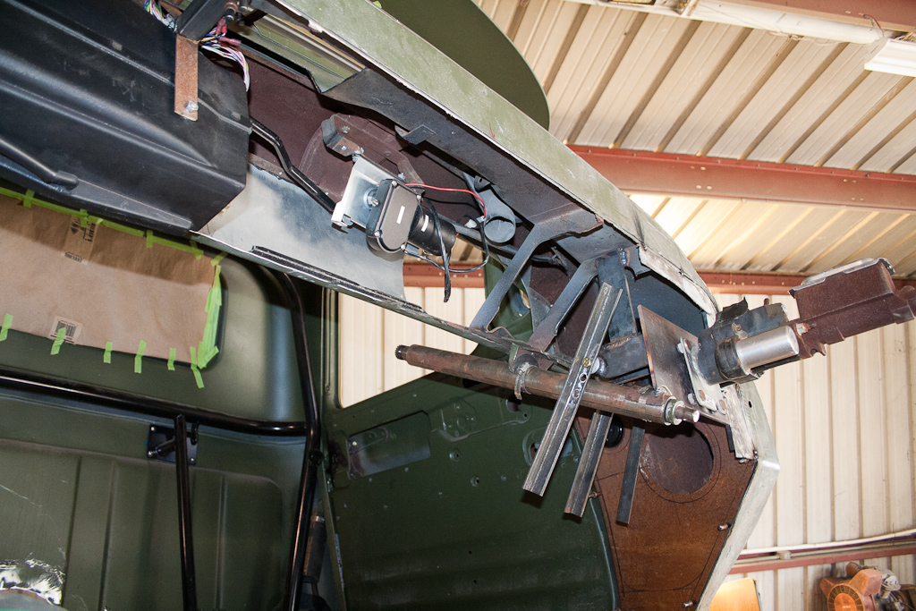
On to the truck, we were going to go to the Dallas Goodguys back in October but we had some issues and couldn’t make it in the end, that cost us a serious chuck of time. Part of that was in some new sheetmetal we wanted on the car. A local shop offered up a good price to bang out some sheetmetal work on the Fire wall of the PT-57 to help with her weight loss program. Let’s just say it didn’t work out to well, pictures are worth a thousand words so they say.
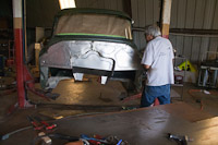
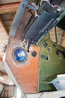
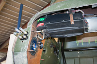
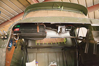
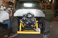
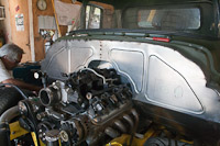
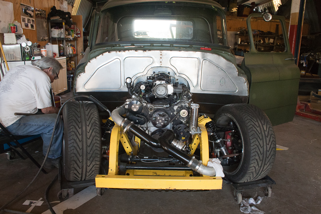
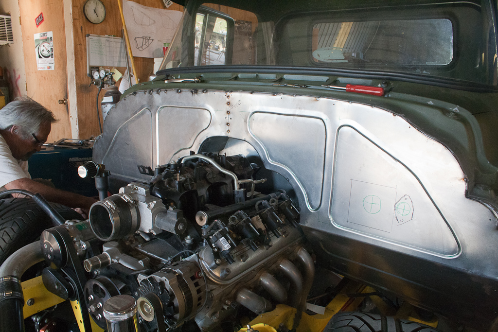
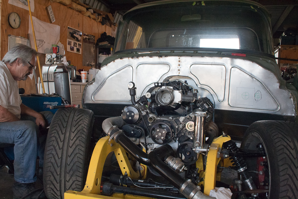
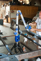
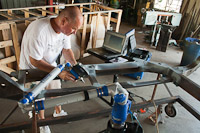
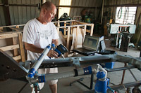
So my father (the retired metal art professor from Texas State) decided he wanted a whack at it finally. We cut out the old crap and removed lots of .250” steel flat stock that was welded in to the truck and used to form the sheetmetal around. Let’s just say I think with the new fire wall and floor tunnel, the truck is probably 20-30 Lbs lighter, and that’s being realistic. We mounted up the Vintage Air Gen 2 AC, tossed in some speakers, and decided to go to a hydro boost master cylinder on the fire wall due to packaging restrictions under the trucks floor and for the ease of daily driving.
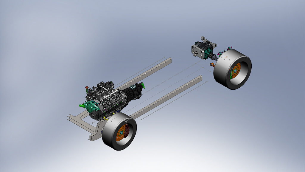
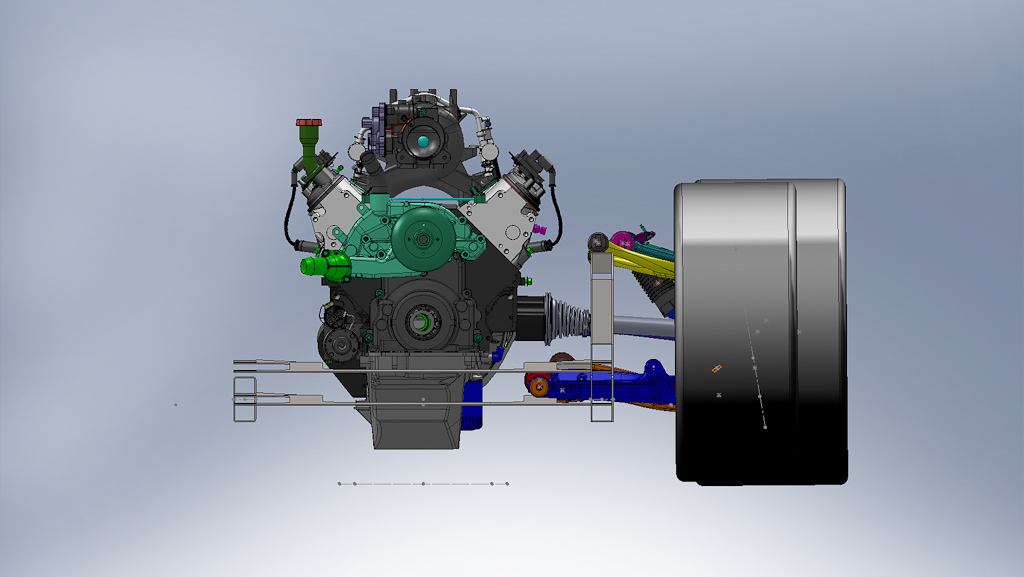
Design ideas
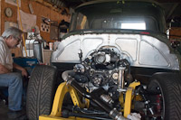
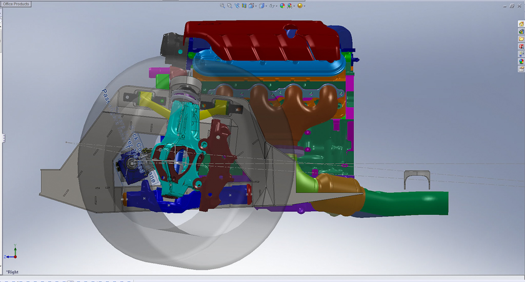
So we had some big problems with the PT-57’s front frame design and its interference with the surrounding systems. The headers and steering were the biggest problems. The headers were so close to the oil filter that in the 2000 miles I put on the truck during testing I burned up 4 oil filters. The headers were so close that is caused the internals of the filter to break. To me driving I suddenly saw the oil pressure drop from 45PSI to almost 20, scared the **** out of me the first time. I feel luck that the starter didn’t burn up, the headers were just as close on that side. Next because of the frame and the headers we didn’t have enough room for a steering linkage I would normally approve of. So we needed more room for that as well. Rack and pinion choice also needed to be reevaluated. We went with a C4 corvette rack on the original design for the availability but with GM cutting back the racks are getting harder and harder to find. I also want 32 degrees of turn in radius for the truck so I can do some more drifting so we turn to Flaming River for that one. We will be using the Flaming River FR40001 with its 6” travel over the 5” travel corvette rack. The rack doesn’t have the clearance issues with the Power Steering lines anymore and we can move the motor down a little further getting the CG down a little more.
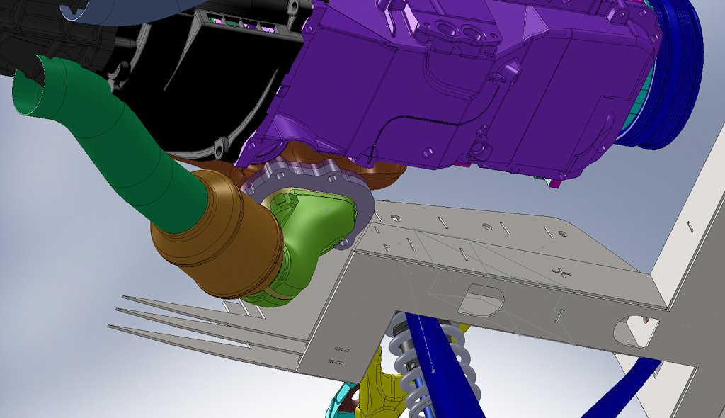
The rear of the PT-57’s frame also needs some re working for the new differential adapter and better turbo integration. The new differential adapter mounts from the top and the current frame didn’t have enough bracing to hold the differential with its short lever-less structure so more tubing needed to be woven in to make the functional support. I love the rear turbos but I need to take the complexity of the boost tubing down a notch so I’m also going to integrate some of the boost tubing into the structure of the frame so we don’t have to fish it through and around the differential and CV Shafts
Finally after some problems with the powder coating (and the final straw with the yellow V4 Frame) We built our own powder coating system again so this time we can do all the little bits and make sure they won’t crack off this time. We can also take out oven up to 800F so I plan to add ceramic (or titanium) coating to the headers and complete exhaust of the PT-57 for even better turbo response (I don’t know it that’s even possible.)
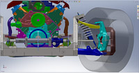
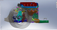
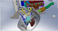
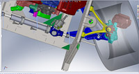
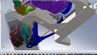
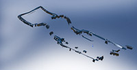
These are some of my rejected frame designs from the last year.


On to the truck, we were going to go to the Dallas Goodguys back in October but we had some issues and couldn’t make it in the end, that cost us a serious chuck of time. Part of that was in some new sheetmetal we wanted on the car. A local shop offered up a good price to bang out some sheetmetal work on the Fire wall of the PT-57 to help with her weight loss program. Let’s just say it didn’t work out to well, pictures are worth a thousand words so they say.

So my father (the retired metal art professor from Texas State) decided he wanted a whack at it finally. We cut out the old crap and removed lots of .250” steel flat stock that was welded in to the truck and used to form the sheetmetal around. Let’s just say I think with the new fire wall and floor tunnel, the truck is probably 20-30 Lbs lighter, and that’s being realistic. We mounted up the Vintage Air Gen 2 AC, tossed in some speakers, and decided to go to a hydro boost master cylinder on the fire wall due to packaging restrictions under the trucks floor and for the ease of daily driving.


Design ideas
So we had some big problems with the PT-57’s front frame design and its interference with the surrounding systems. The headers and steering were the biggest problems. The headers were so close to the oil filter that in the 2000 miles I put on the truck during testing I burned up 4 oil filters. The headers were so close that is caused the internals of the filter to break. To me driving I suddenly saw the oil pressure drop from 45PSI to almost 20, scared the **** out of me the first time. I feel luck that the starter didn’t burn up, the headers were just as close on that side. Next because of the frame and the headers we didn’t have enough room for a steering linkage I would normally approve of. So we needed more room for that as well. Rack and pinion choice also needed to be reevaluated. We went with a C4 corvette rack on the original design for the availability but with GM cutting back the racks are getting harder and harder to find. I also want 32 degrees of turn in radius for the truck so I can do some more drifting so we turn to Flaming River for that one. We will be using the Flaming River FR40001 with its 6” travel over the 5” travel corvette rack. The rack doesn’t have the clearance issues with the Power Steering lines anymore and we can move the motor down a little further getting the CG down a little more.
The rear of the PT-57’s frame also needs some re working for the new differential adapter and better turbo integration. The new differential adapter mounts from the top and the current frame didn’t have enough bracing to hold the differential with its short lever-less structure so more tubing needed to be woven in to make the functional support. I love the rear turbos but I need to take the complexity of the boost tubing down a notch so I’m also going to integrate some of the boost tubing into the structure of the frame so we don’t have to fish it through and around the differential and CV Shafts
Finally after some problems with the powder coating (and the final straw with the yellow V4 Frame) We built our own powder coating system again so this time we can do all the little bits and make sure they won’t crack off this time. We can also take out oven up to 800F so I plan to add ceramic (or titanium) coating to the headers and complete exhaust of the PT-57 for even better turbo response (I don’t know it that’s even possible.)
These are some of my rejected frame designs from the last year.


 07-04-2011, 02:42 PM
#43
Launching!
Thread Starter
Join Date: Jan 2007
Location: Luling TX In the Hot Rod Shop
Posts: 294
Likes: 0
Received 3 Likes
on
3 Posts
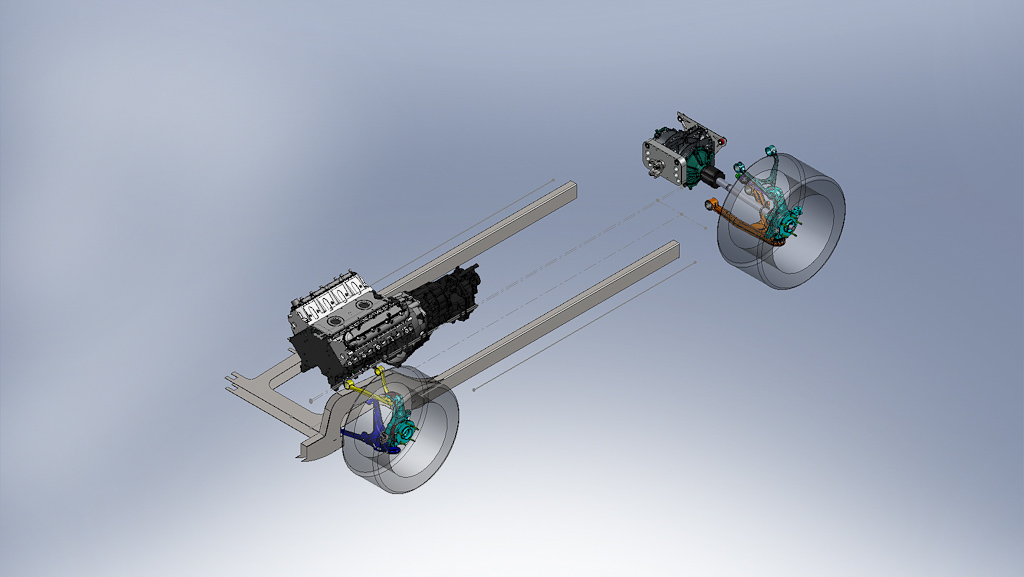
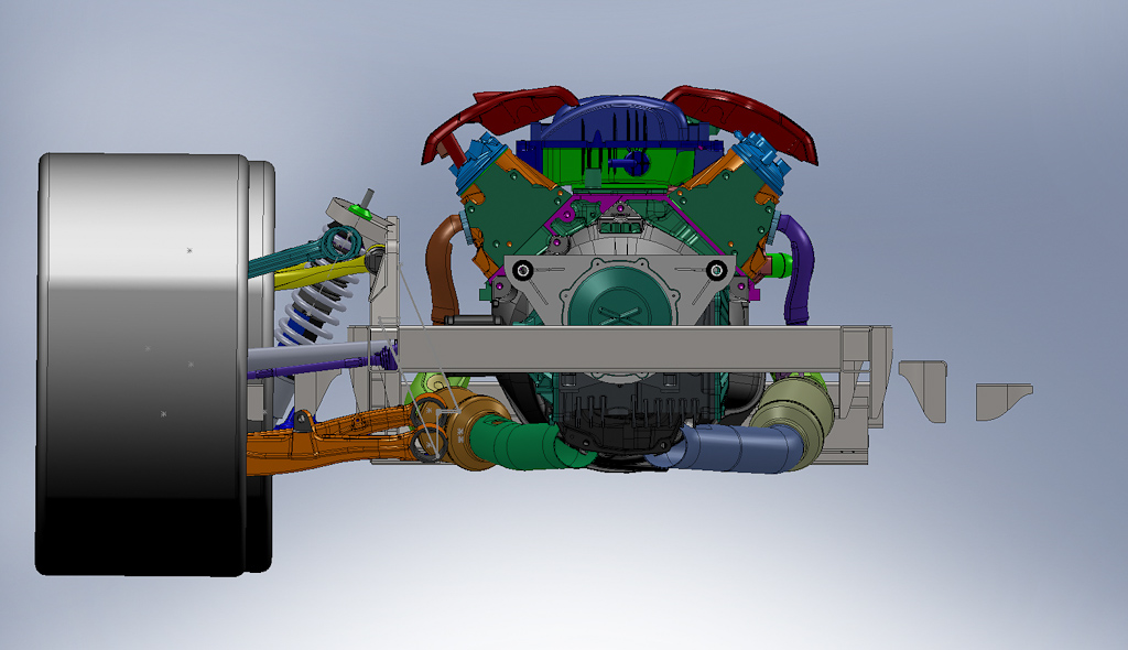
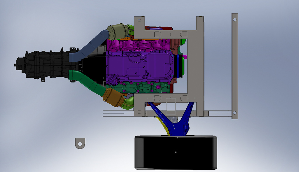
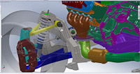
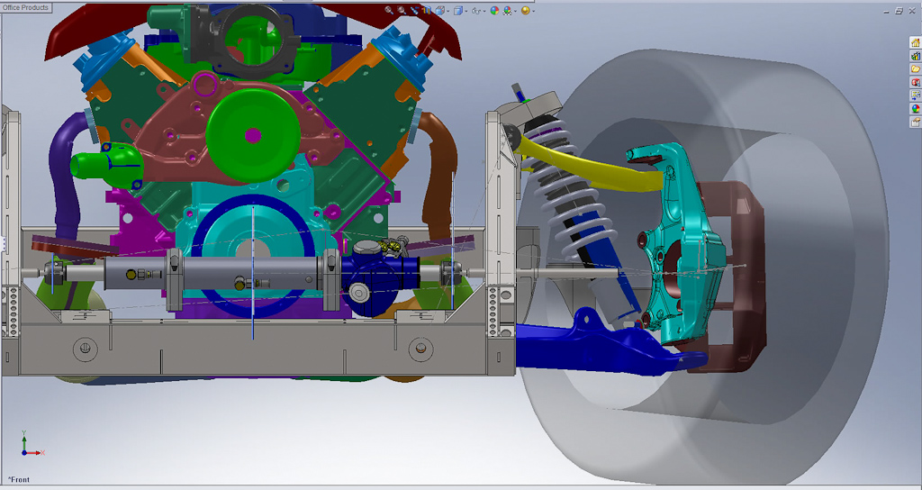
And finally after 4 rejected frames (I think) I’ve finally found the right combination to make the front really work out, take a look and let me know what you think.


2011 Should be a fun year for the PT-57 and I hope she will fully evolve into the PT nightmare I want her to be.
Thanks
Russell Alexander
Hot Rod Jim’s
http://www.hotrodjim.com


2011 Should be a fun year for the PT-57 and I hope she will fully evolve into the PT nightmare I want her to be.
Thanks
Russell Alexander
Hot Rod Jim’s
http://www.hotrodjim.com
 07-10-2011, 06:46 PM
#48
Launching!
Thread Starter
Join Date: Jan 2007
Location: Luling TX In the Hot Rod Shop
Posts: 294
Likes: 0
Received 3 Likes
on
3 Posts
thanks guys here's the last update I missed and forgot to update here on LS1tech
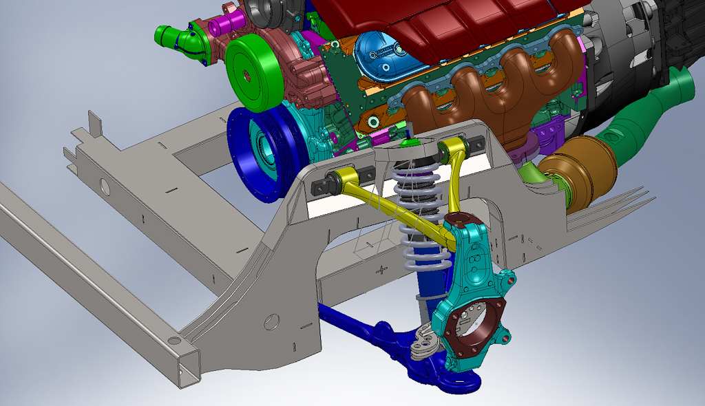
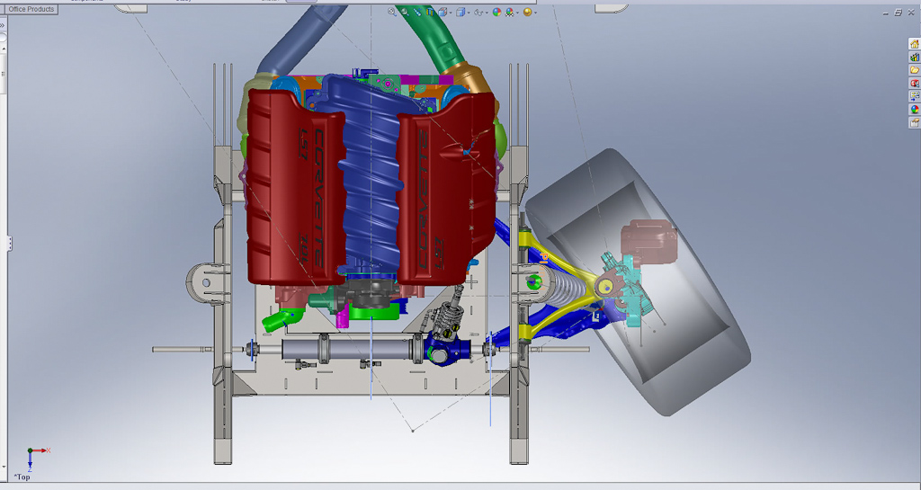
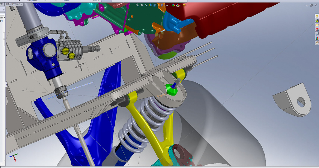
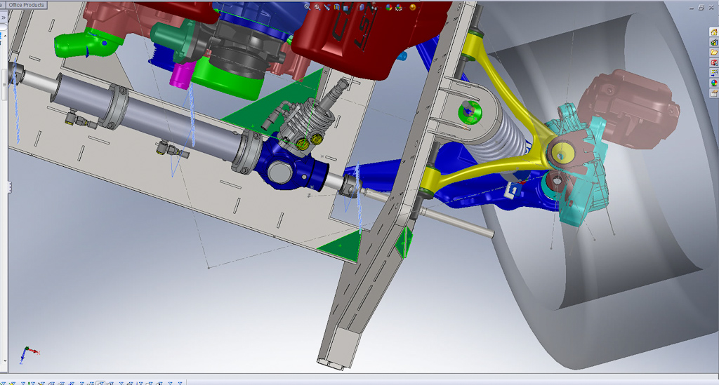
So I’m almost done with the new frame front section. Right now it looks to be right at 101.26 lbs. I’m looking for more room I can lighten the front up without losing structural integrity. I still need to add the rear shock brace and the sway bar hole so I look to pick up another 3-4 lbs there and I’m figuring on 2-3lbs of welds. The old one was just over 75lbs in the computer but I didn’t have all the parts drawn so probably closer to 85lbs with those parts and welding wire.
We now have a full 34 degrees of turning radius with 275/xx/Rxx Hoosiers. FYI Hoosiers have a serious edge on them making them almost .300” wider than a normal 275, So I can probably run 295 Front tire on this configuration and still turn around in 2 lanes without punching on it.
Flaming River Rack and Pinion, BIG thanks to those guys for sharing a part file for my design I drew one off the rack I had but there are too many compound angles and I screwed up a little here and there. We now have a much beefier rack up front to take the load and its only 2 lbs heavier than the C4 corvette rack I was using.
PFADT’s superior upper shock mount with their Coilover shocks. I love the OE Pfadt shocks I have already, the map is great and I plan on keeping them. But with some serious luck I’ll be able to get a set of these for my truck, http://www.pfadtracing.com/catalog/p...7606d692d513ba this will shave some weight from the suspension and most importantly the un sprung weight and I’ll be able to dial in my compression and rebound independently which will be important when I get back on the track.
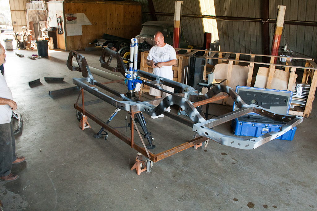
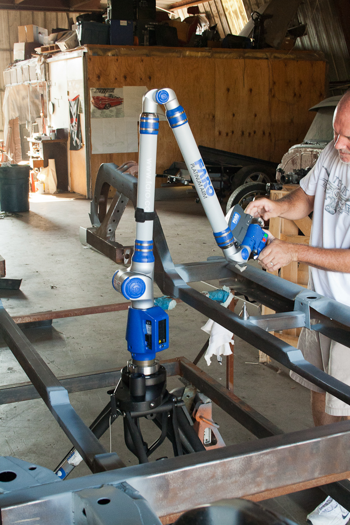
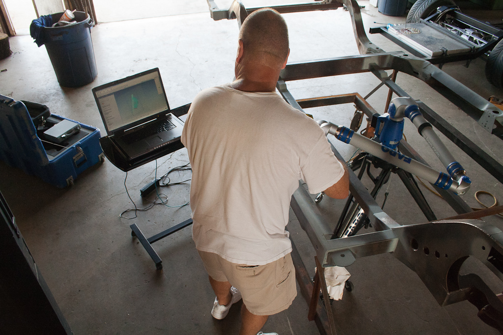
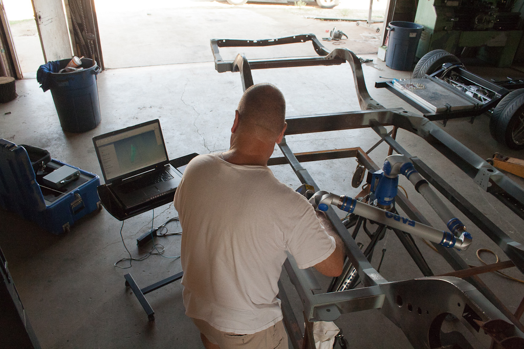
I’m waiting on a visit from these guys http://www.absolutegeometries.com/ My plan is to scan several portions of the body into a 3D point cloud so I can drop it into the computer and overlay it with the truck to make sure we have clearance. Here are some video for you guys who have never seen one of these 3D scanners at work.
http://www.youtube.com/watch?v=oZKrwkzO6-w http://www.youtube.com/watch?v=ywFb-FnT8rA


More coming soon
Later
-Russell
So I’m almost done with the new frame front section. Right now it looks to be right at 101.26 lbs. I’m looking for more room I can lighten the front up without losing structural integrity. I still need to add the rear shock brace and the sway bar hole so I look to pick up another 3-4 lbs there and I’m figuring on 2-3lbs of welds. The old one was just over 75lbs in the computer but I didn’t have all the parts drawn so probably closer to 85lbs with those parts and welding wire.
We now have a full 34 degrees of turning radius with 275/xx/Rxx Hoosiers. FYI Hoosiers have a serious edge on them making them almost .300” wider than a normal 275, So I can probably run 295 Front tire on this configuration and still turn around in 2 lanes without punching on it.
Flaming River Rack and Pinion, BIG thanks to those guys for sharing a part file for my design I drew one off the rack I had but there are too many compound angles and I screwed up a little here and there. We now have a much beefier rack up front to take the load and its only 2 lbs heavier than the C4 corvette rack I was using.
PFADT’s superior upper shock mount with their Coilover shocks. I love the OE Pfadt shocks I have already, the map is great and I plan on keeping them. But with some serious luck I’ll be able to get a set of these for my truck, http://www.pfadtracing.com/catalog/p...7606d692d513ba this will shave some weight from the suspension and most importantly the un sprung weight and I’ll be able to dial in my compression and rebound independently which will be important when I get back on the track.
I’m waiting on a visit from these guys http://www.absolutegeometries.com/ My plan is to scan several portions of the body into a 3D point cloud so I can drop it into the computer and overlay it with the truck to make sure we have clearance. Here are some video for you guys who have never seen one of these 3D scanners at work.
http://www.youtube.com/watch?v=oZKrwkzO6-w http://www.youtube.com/watch?v=ywFb-FnT8rA


More coming soon
Later
-Russell
07-10-2011, 06:50 PM
#49

Thats so fricken cool. lol
 07-11-2011, 09:40 AM
#50
Launching!
Thread Starter
Join Date: Jan 2007
Location: Luling TX In the Hot Rod Shop
Posts: 294
Likes: 0
Received 3 Likes
on
3 Posts
Update 2011.07.10
3D Scanning and getting the last parts to the puzzle
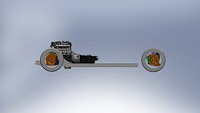
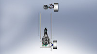
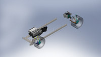
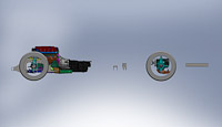
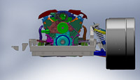
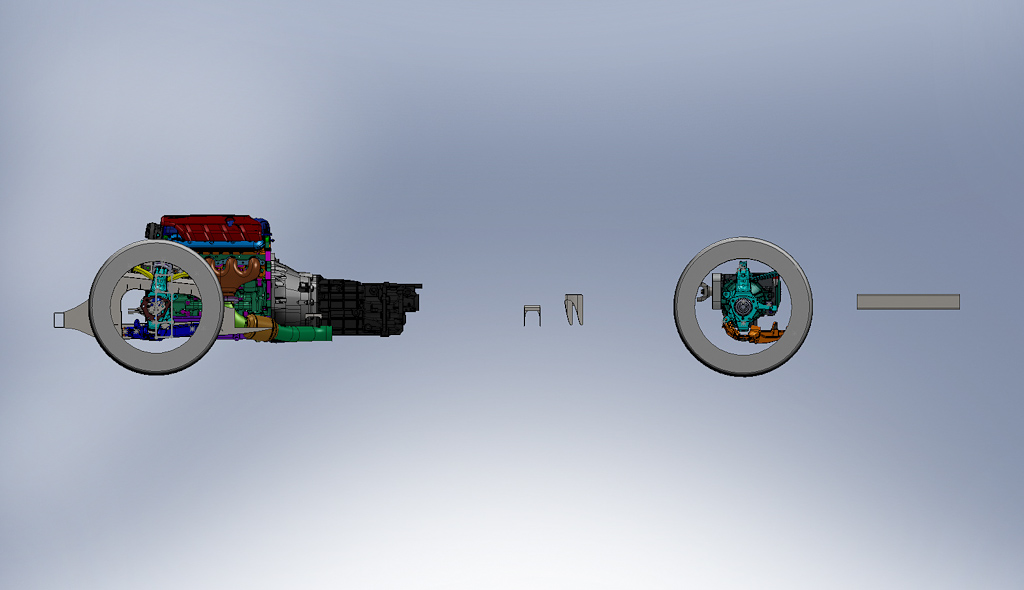
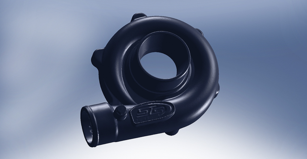
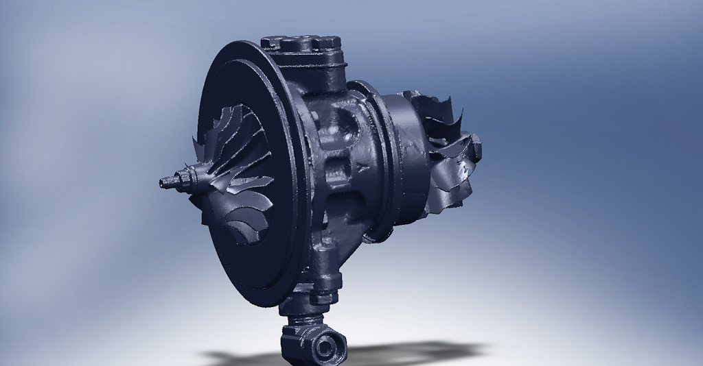
So after talking through several emails with Mike owner of Absolute Geometry (http://www.absolutegeometries.com) I figured out all I could without seeing and working with the parts myself. I spent several weeks of trying to get some free time and getting my schedule to align so I could head up to his place and talk in person with the equipment for demonstration. I also decided it would be a good idea to get some small parts I wanted scanned so I’d have something to play with in the computer to better understand the final product. The STS Turbos I want to really suck into the chassis and make them fit so I took one of the turbos and took it in 3 parts, the compressor housing, the turbin housing and the center section. This would give me 3 separate parts so I can clock the turbo in the computer for future chassis project and really fit the turbo in to the chassis, here are the results.


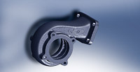

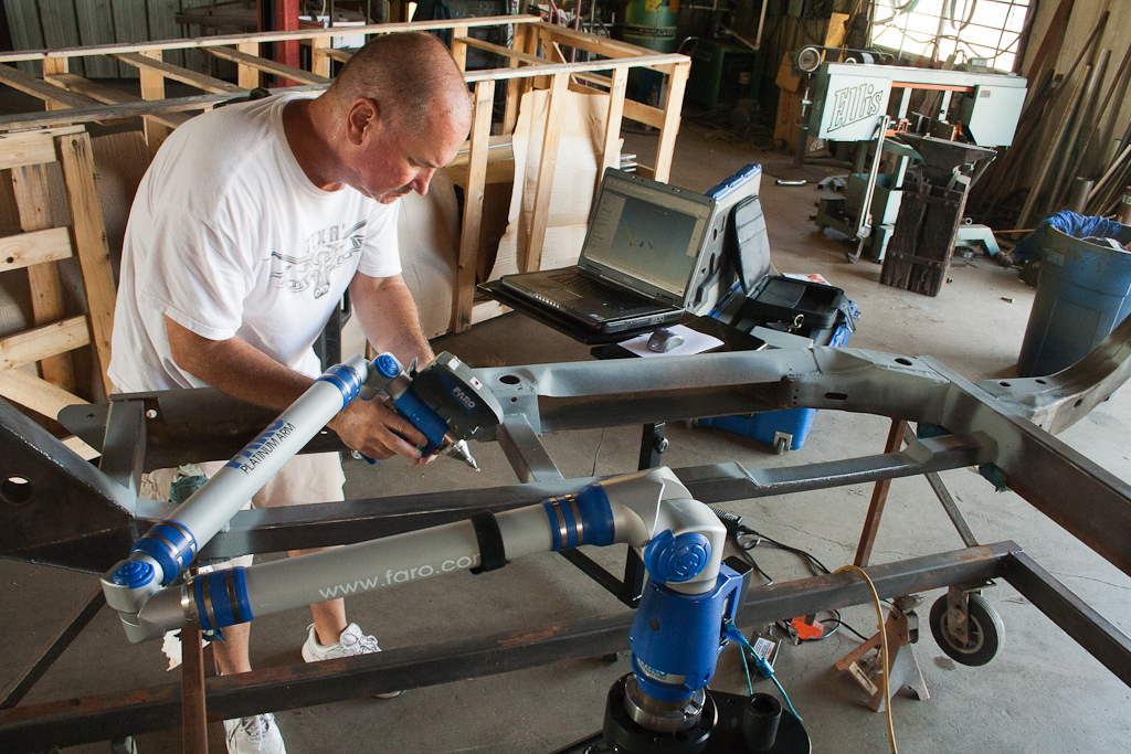
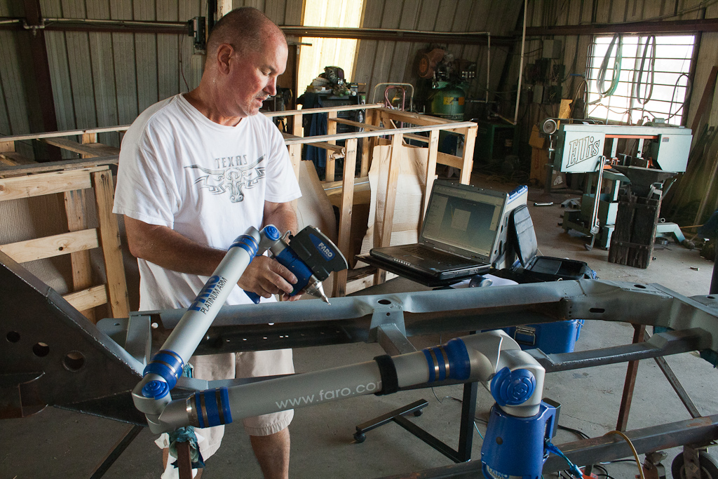
The I’m having a little trouble making 3D surface files out of them but that’s just because my version of Solidworks doesn’t have the 3D scanning software and I’m forced to go to a friend’s place to use his premium copy so I haven’t had a lot of time to play with it. I also found out he can do the laser scan of the surface and then go in and get hard points with the FARO pointer. The points come in as a IGS file that will lay over the scan. The advantage to this is I don’t have to do any work to the scan to change it from a STL file into anything else. I have the hard points to measure from and I can see where something might interfere with the outside and change that.
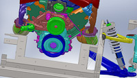
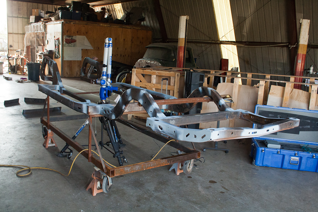
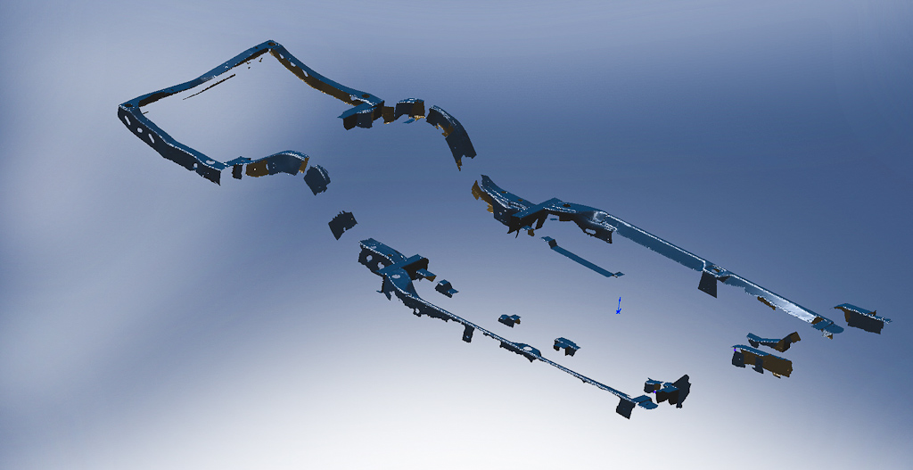
So I showed this to a friend and so he asked me to supervise the scanning of his A-Body frame. After the scan it he called and decided he wants the back to Lay frame. So he asked if I could make a quick modification and make up some rear arches that will move the loop up 4 inches. It took 15 minutes with the scan data and everything’s to scale, take a look.


So my plan is twofold. One is to have the bottom of some of my other projects scanned so in the future I have all the body bracing, inner and outer fender, firewalls and core supports all in the computer before I start so I can build my frame and look to see if it will clear without having to spend a week moving the body, building a prototype moving everything around just to find out one section is .500 to far to the left and hitting a body brace or you can’t get the wheels off, the list goes on. The second part of the plan is to check against deviation from the design. When we’re done with the frame we’ll scan the first few out of the Jig to make sure they are all within speck and not warped all to hell. The best design is useless if you can reproduce it accurately.
More to come
-Russell
3D Scanning and getting the last parts to the puzzle
So after talking through several emails with Mike owner of Absolute Geometry (http://www.absolutegeometries.com) I figured out all I could without seeing and working with the parts myself. I spent several weeks of trying to get some free time and getting my schedule to align so I could head up to his place and talk in person with the equipment for demonstration. I also decided it would be a good idea to get some small parts I wanted scanned so I’d have something to play with in the computer to better understand the final product. The STS Turbos I want to really suck into the chassis and make them fit so I took one of the turbos and took it in 3 parts, the compressor housing, the turbin housing and the center section. This would give me 3 separate parts so I can clock the turbo in the computer for future chassis project and really fit the turbo in to the chassis, here are the results.

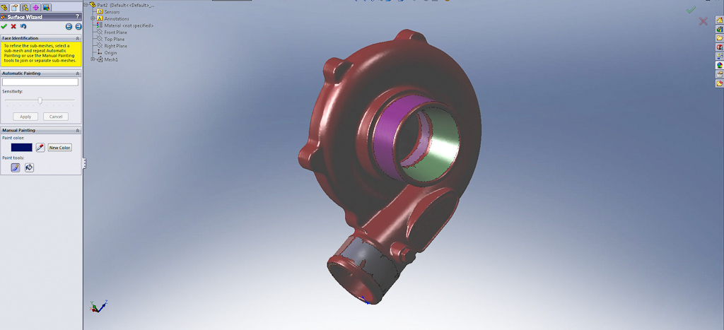
The I’m having a little trouble making 3D surface files out of them but that’s just because my version of Solidworks doesn’t have the 3D scanning software and I’m forced to go to a friend’s place to use his premium copy so I haven’t had a lot of time to play with it. I also found out he can do the laser scan of the surface and then go in and get hard points with the FARO pointer. The points come in as a IGS file that will lay over the scan. The advantage to this is I don’t have to do any work to the scan to change it from a STL file into anything else. I have the hard points to measure from and I can see where something might interfere with the outside and change that.
So I showed this to a friend and so he asked me to supervise the scanning of his A-Body frame. After the scan it he called and decided he wants the back to Lay frame. So he asked if I could make a quick modification and make up some rear arches that will move the loop up 4 inches. It took 15 minutes with the scan data and everything’s to scale, take a look.


So my plan is twofold. One is to have the bottom of some of my other projects scanned so in the future I have all the body bracing, inner and outer fender, firewalls and core supports all in the computer before I start so I can build my frame and look to see if it will clear without having to spend a week moving the body, building a prototype moving everything around just to find out one section is .500 to far to the left and hitting a body brace or you can’t get the wheels off, the list goes on. The second part of the plan is to check against deviation from the design. When we’re done with the frame we’ll scan the first few out of the Jig to make sure they are all within speck and not warped all to hell. The best design is useless if you can reproduce it accurately.
More to come
-Russell


 07-07-2013, 05:41 PM
#54
Launching!
Thread Starter
Join Date: Jan 2007
Location: Luling TX In the Hot Rod Shop
Posts: 294
Likes: 0
Received 3 Likes
on
3 Posts
Well........ The word it she's in a pill of parts. The body in on a big shelf in my shop and the complete frame has been scrapped. I'm going to design a new one but the market told me no on wanted to pay for C5/6 stuff. So I'm working on a C4 version right now to give people a more affordable option then I'll get back on the C5/6 goodies.
Here's the C4 project, We're designing it as a kit frame so you can just buy the parts and weld it together yourself at home. The frames self Jig so you don't even need a really complex system to put it together.
https://ls1tech.com/forums/conversio...me-design.html
Later
-Russell
Here's the C4 project, We're designing it as a kit frame so you can just buy the parts and weld it together yourself at home. The frames self Jig so you don't even need a really complex system to put it together.
https://ls1tech.com/forums/conversio...me-design.html
Later
-Russell