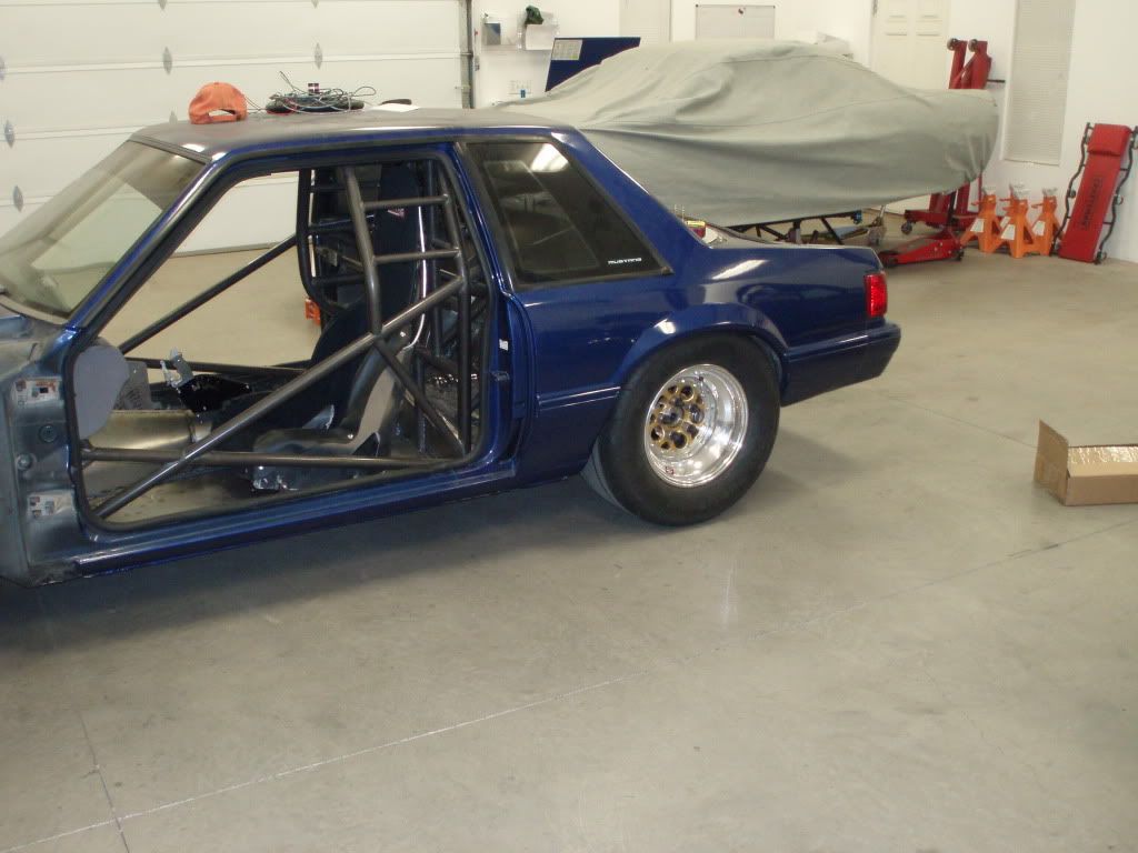
25.5 Mustang Coupe project.
Thanks, guys. But I'm a newbie to the cage building stuff. I'm just a engine builder looking to diversify.
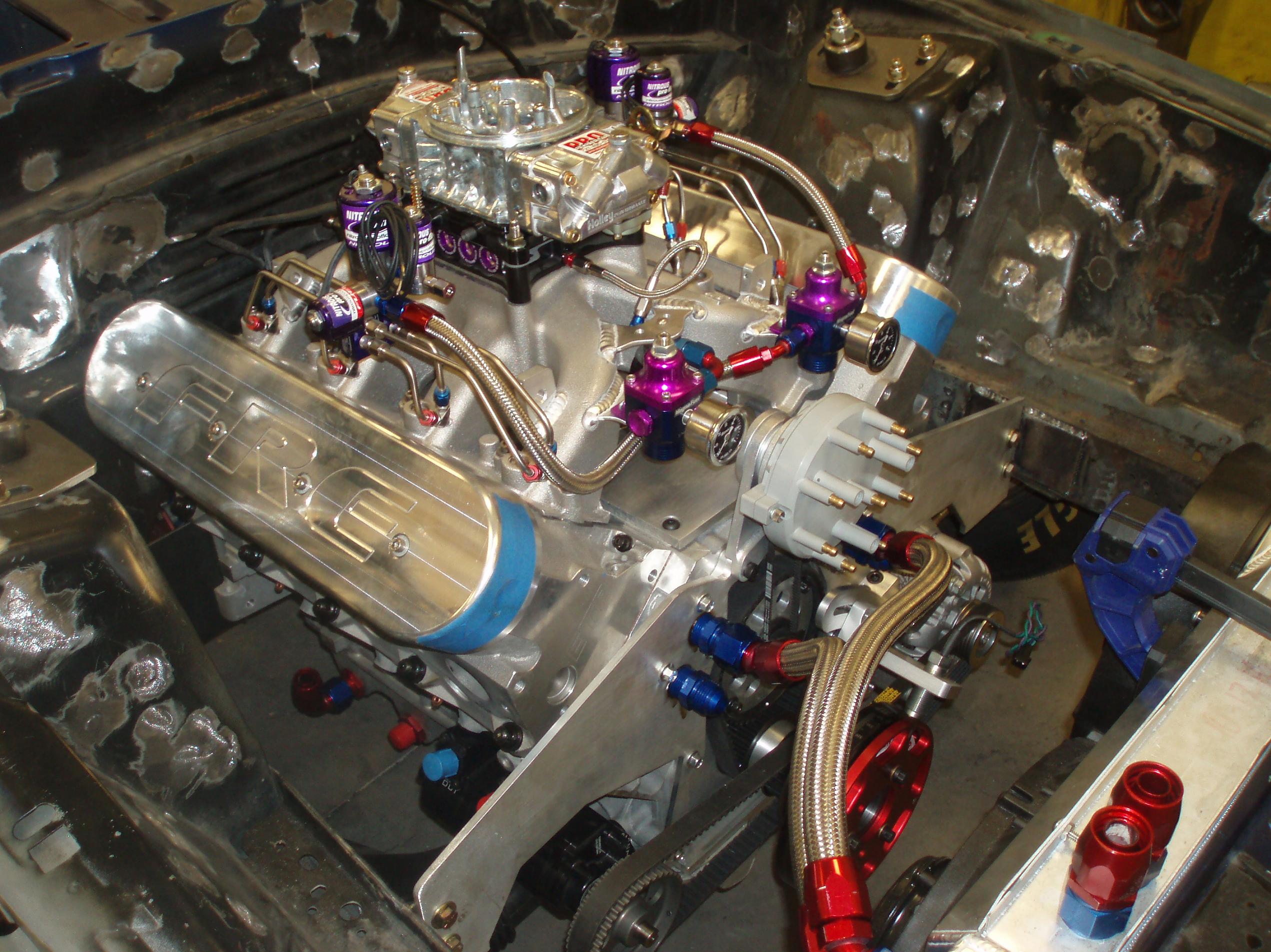
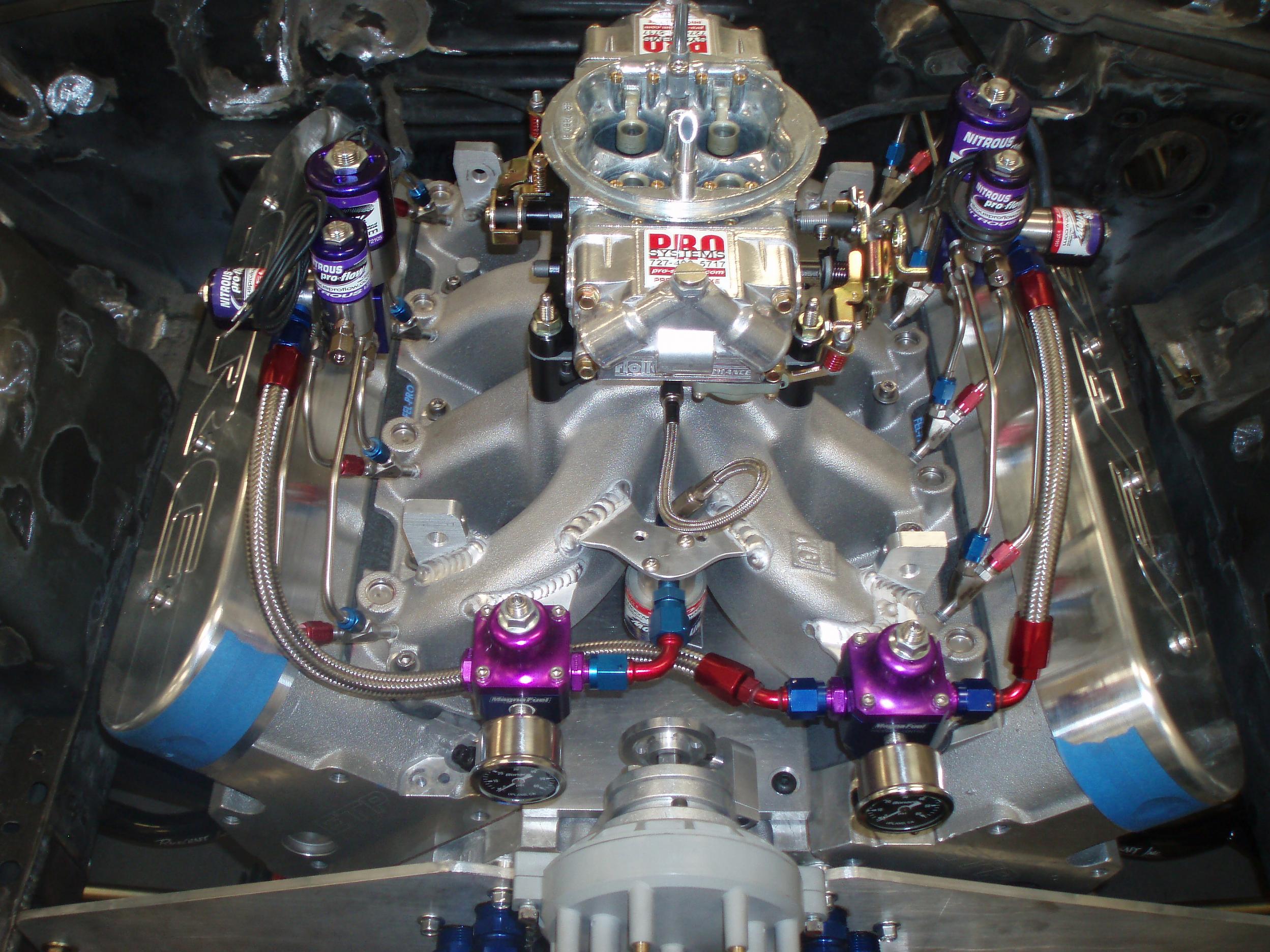
And the engine that is going in this project is a carry over for another project I have in the works. It's a 416" LS nitrous engine that should fly in this light weight car. Here's a pic, but I won't be using the distributor set-up on this car... It will be a tradition COP set-up. And the T/B Elbow is out too. I'll be eliminating that, and will be mounting the T/B, vertically on top of the nitrous plate. I'll post a pic after I get it set-up and in the car. <(More parts to make, first) :-/
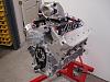
And the engine that is going in this project is a carry over for another project I have in the works. It's a 416" LS nitrous engine that should fly in this light weight car. Here's a pic, but I won't be using the distributor set-up on this car... It will be a tradition COP set-up. And the T/B Elbow is out too. I'll be eliminating that, and will be mounting the T/B, vertically on top of the nitrous plate. I'll post a pic after I get it set-up and in the car. <(More parts to make, first) :-/

Thanks, guys... It's been a lot of fun building this thing.
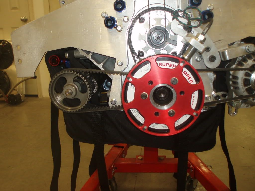
A little up-date on this project. It passed certification for 25.2 & 25.3 specs, so I'm happy about that. Now I've started working on the motor plates. Here is a rough draft of what I've got so far. The motor plate attaches to all of the timing cover/Jesel cover bolts and the water pump bolts... It should be super secure/strong. And that's a factory LS F-body alternator too and it's fully adjustable for belt tension. The pulley on the opposite side is for the dry-sump pump.

A little up-date on this project. It passed certification for 25.2 & 25.3 specs, so I'm happy about that. Now I've started working on the motor plates. Here is a rough draft of what I've got so far. The motor plate attaches to all of the timing cover/Jesel cover bolts and the water pump bolts... It should be super secure/strong. And that's a factory LS F-body alternator too and it's fully adjustable for belt tension. The pulley on the opposite side is for the dry-sump pump.
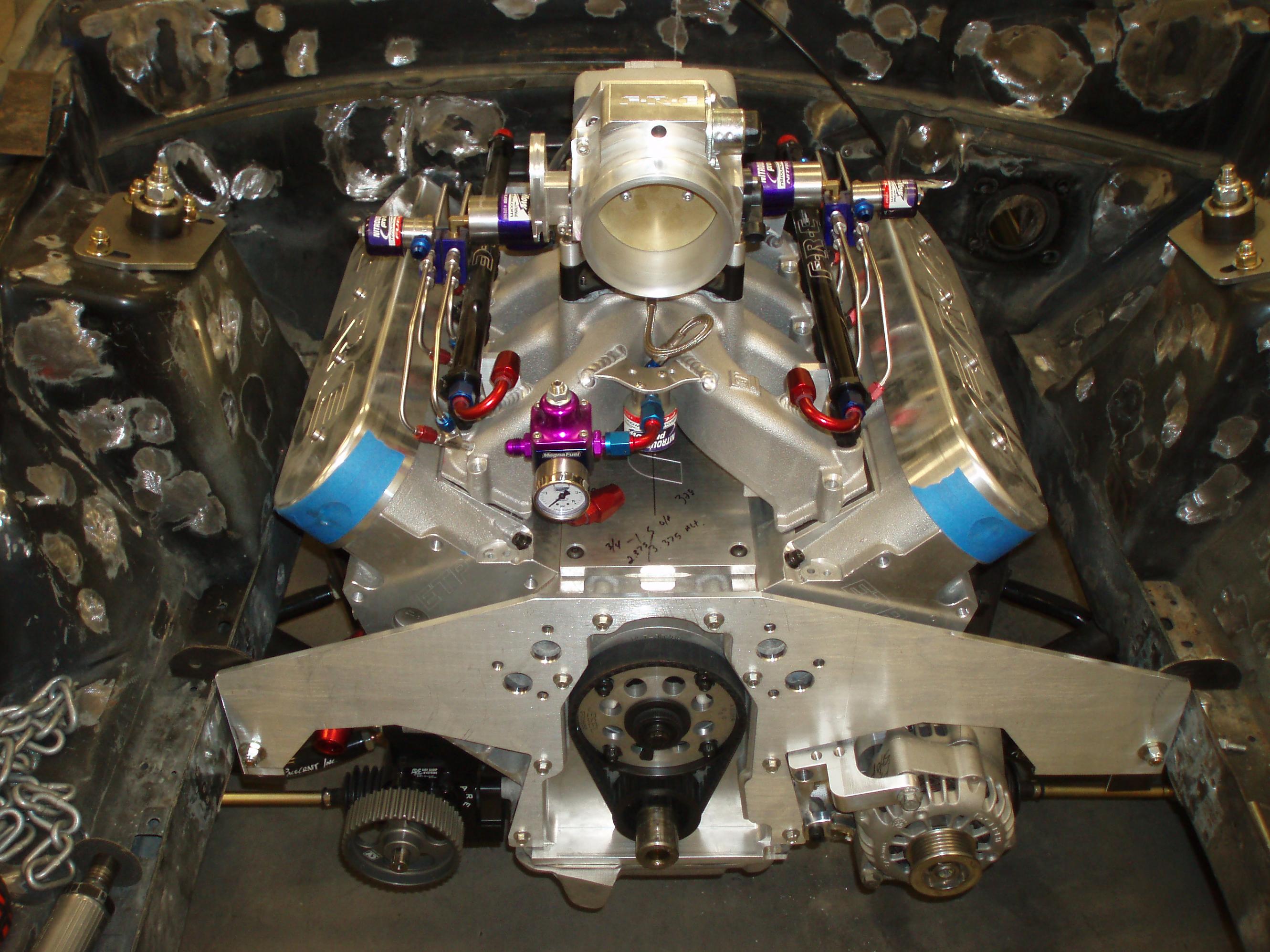
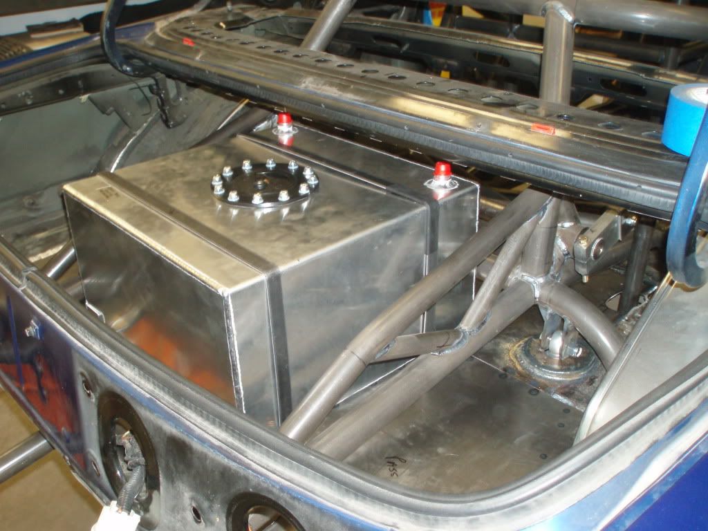
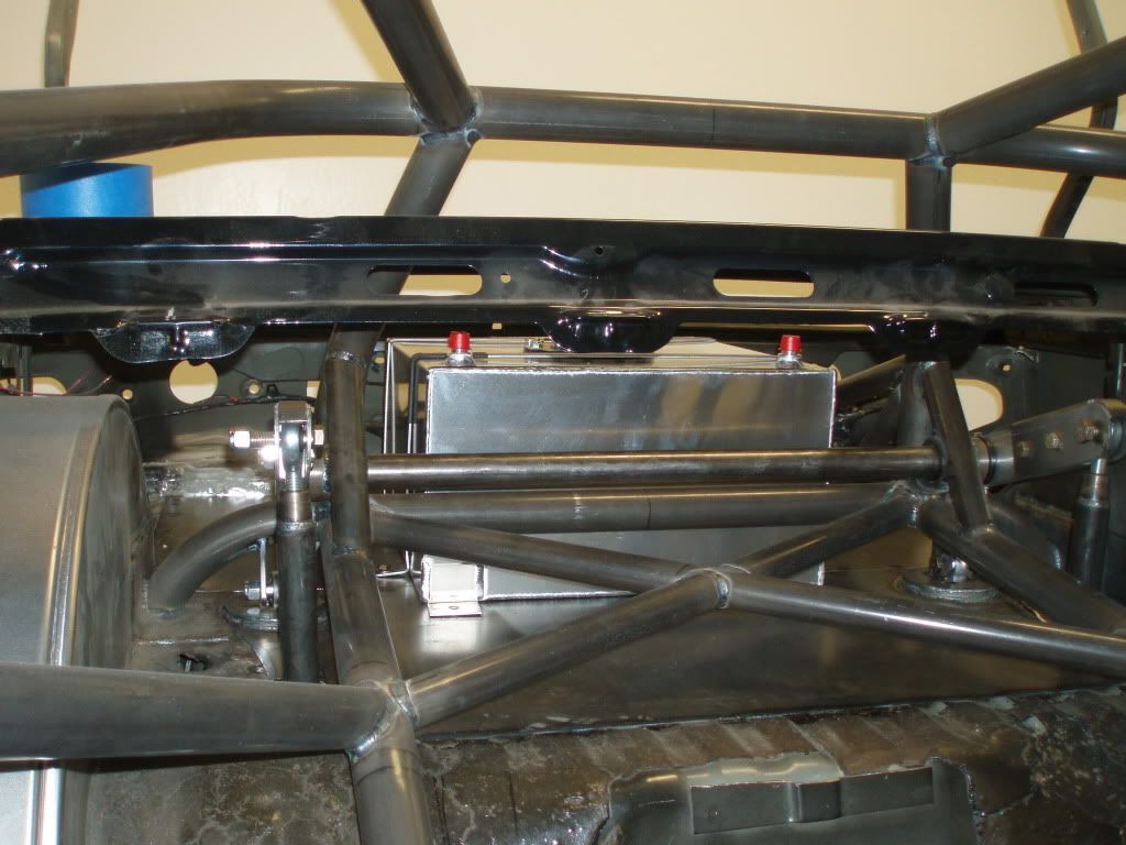
Got a little more work done. Got the motor and mid plate finished with a mock up block and got the fuel cell fitted. I have a little more tin work to do back there but it's gettin' close. (Just doing fit checks, not installing yet)
The engine should be ready by next week (I changed some things again) but I'm hopin' it will be ready to drop in soon.

The engine should be ready by next week (I changed some things again) but I'm hopin' it will be ready to drop in soon.
 Right now I'm making radiator mounts and hoses...
LS1 Tech Stories
The Best V8 Stories One Small Block at Time

Top 10 Greatest Cadillac V Series Performance Models Ever, Ranked
Pouria Savadkouei
Top 10 Most Powerful Chevy Trucks Ever Made!

Hennessey's New Supercharged Silverado ZR2 Has 700 HP
Verdad Gallardo
Coachbuilt N2A Anteros Is an LS2-Powered C6 Corvette In Italian Clothes
Verdad Gallardo
Awesome K5 Blazer Restomod Comes With C7 Corvette Power
Verdad Gallardo
10 Camaros You Should Never Buy

10 LS Engine Myths That Refuse to Die
Verdad Gallardo
Five Reasons the Camaro Was the Most Pivotal Player in the Pony Car Wars 2.0
Brett Foote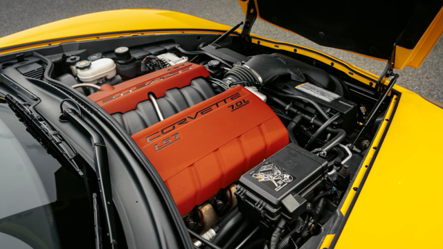
10 Reasons the LS7 Is GM's Most Extreme Naturally Aspirated V8 Engine Ever
Verdad Gallardo
^^^^Thanks!^^^^
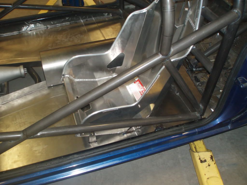
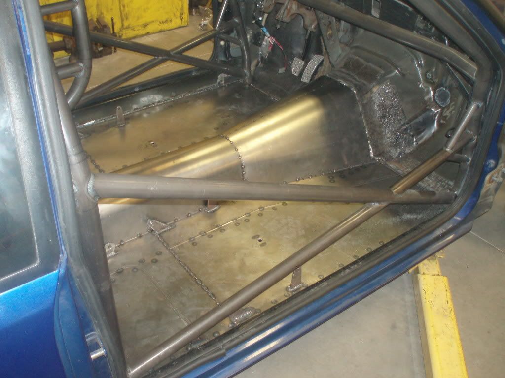
Got some tin work done. Everything is mocked up where the floor ties into the back half of the car and the driver side seat is located and well as the seat belt tabs. The passenger seat will go in the same way.
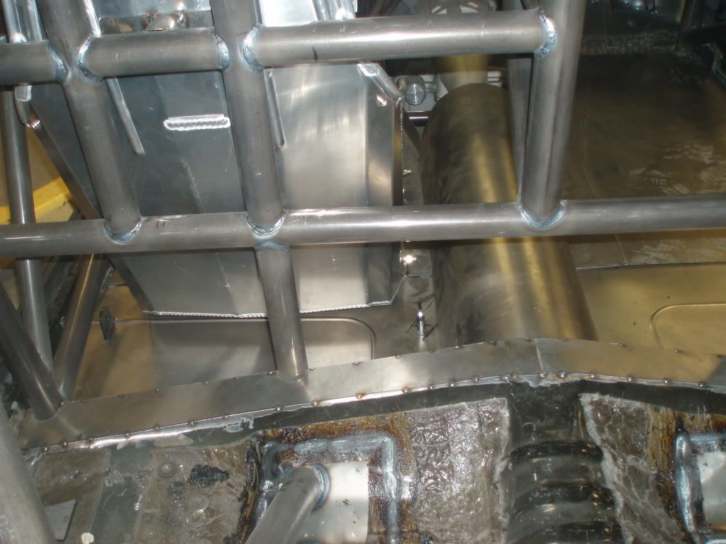
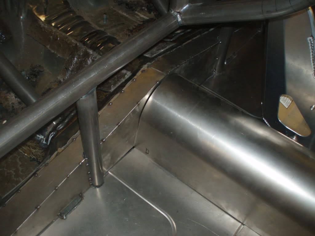
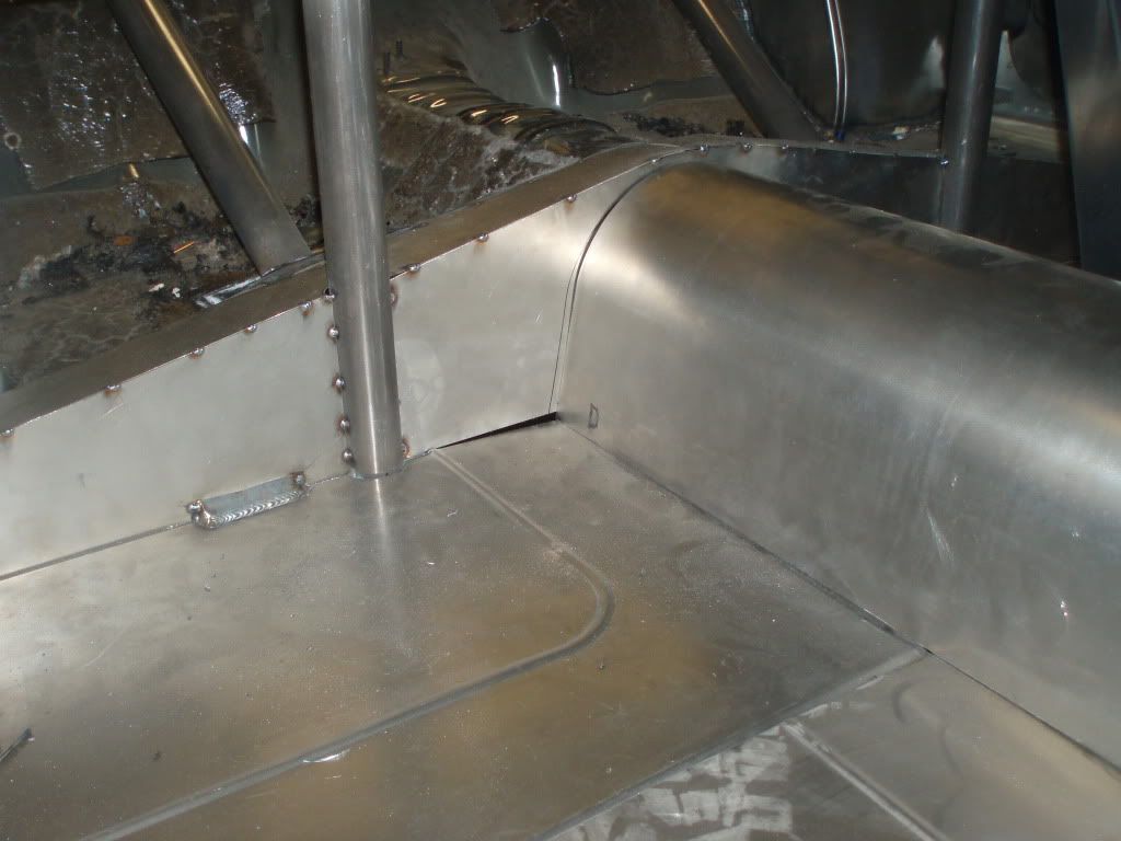
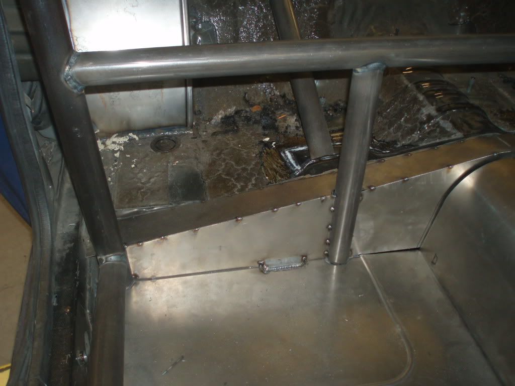
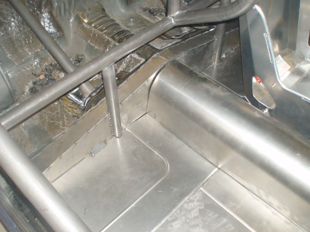
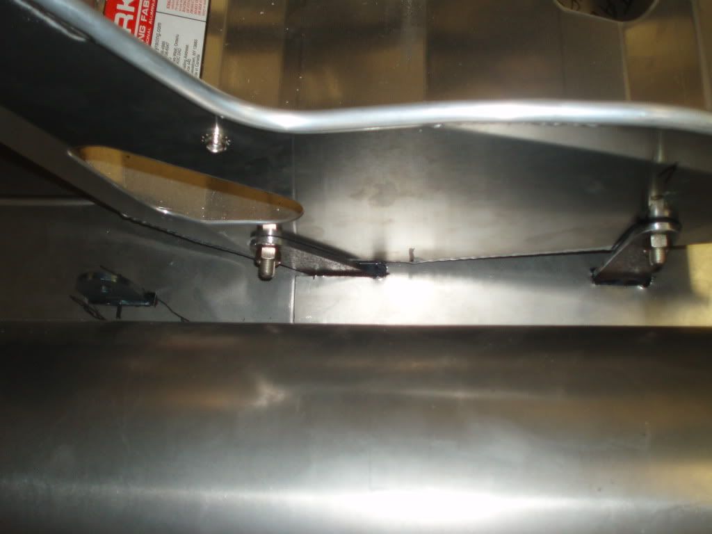
Got some tin work done. Everything is mocked up where the floor ties into the back half of the car and the driver side seat is located and well as the seat belt tabs. The passenger seat will go in the same way.
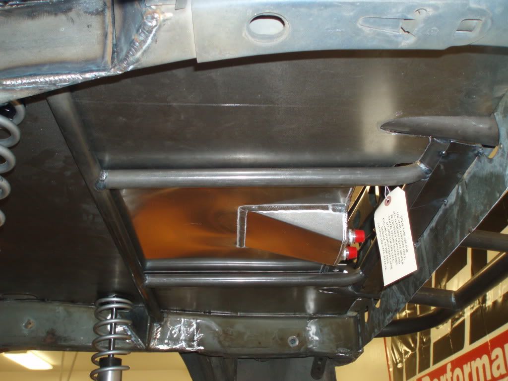
Here are some pics of the "oil containment device" ... What a pain in the *** to deal with. :-/ Anyway, here is the universial fit RCI blanket and it works pretty good. I do have to tweek it a bit but I think I can make it work. <(But I'll never run the thing on the street)... Talk about a block heater! Yikes!
But one problem I did run into is the Dyna Tech Fox body headers with the blanket... Not gonna work. The tubs are too close to the blanket and it will burn/melt it. Soooooo... I have to make my own headers if I plan on going with this set-up. $#@%^&!!!!!
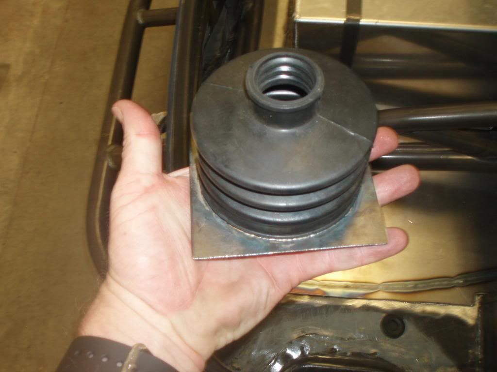
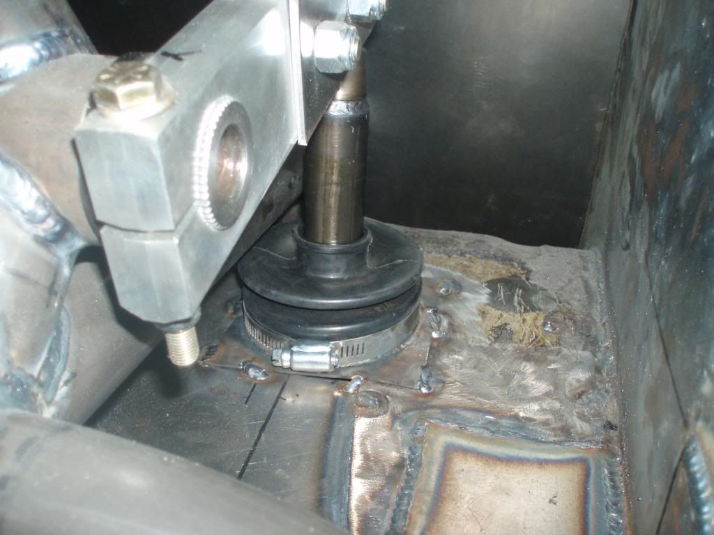
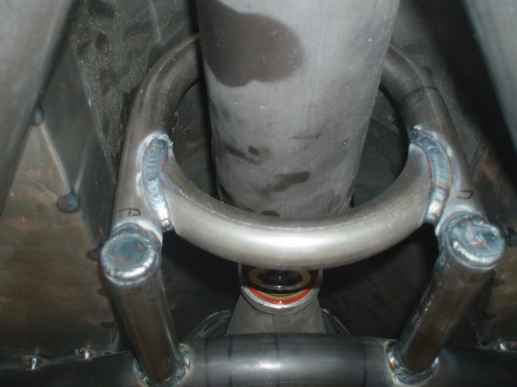
I also got my smoke out boots done. <(smoke out of the passenger compartment) The boots ride on the anti-sway bar down tubes so no smoke inside the car after a burn out.
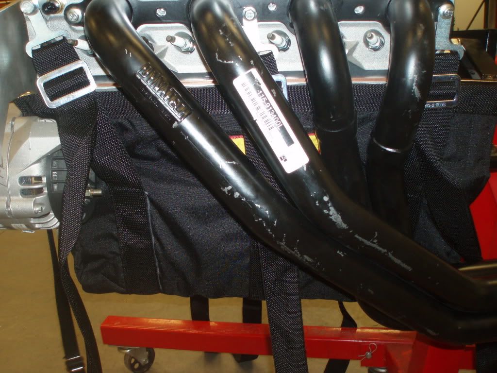
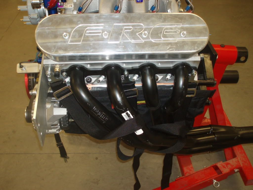
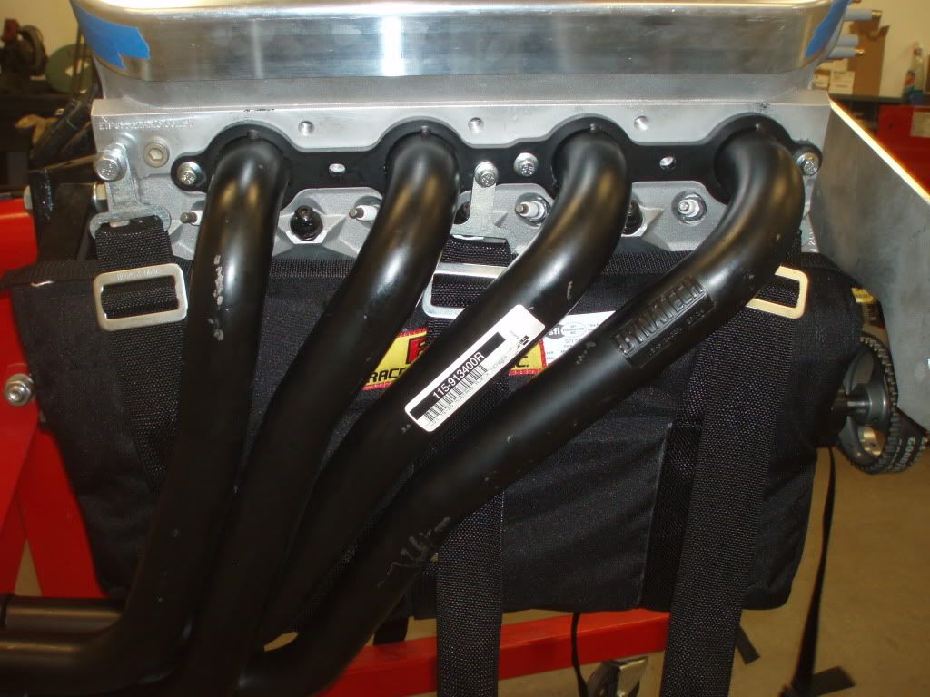
But one problem I did run into is the Dyna Tech Fox body headers with the blanket... Not gonna work. The tubs are too close to the blanket and it will burn/melt it. Soooooo... I have to make my own headers if I plan on going with this set-up. $#@%^&!!!!!
I also got my smoke out boots done. <(smoke out of the passenger compartment) The boots ride on the anti-sway bar down tubes so no smoke inside the car after a burn out.

what backspacing wheel did you end up with?
also how far are the lower control arm brackets moved in on the housing?
it looks like they are moved in quite a bit. no worries about affecting the triangulation of the factory 4-link?
very nice project!
also how far are the lower control arm brackets moved in on the housing?
it looks like they are moved in quite a bit. no worries about affecting the triangulation of the factory 4-link?
very nice project!
3.5" off each side with 5" backspacing on the rims. Housing LCA brackets re-located to line the LCA's to the original frame mounting points. The LCA's are moved inboard with RaceCraft offset spacers for tire clearance.
keep the pics coming!!!
looks good. i am doing my mustang now as well. i am still using an 8.8 but i have the racecraft lower control arm mounts for the housings and moved them in 2" each side. i just didnt know how much you can move them in without messing up the triangulation and having to run a wishbone set-up. my rear is narrowed 3" each side and i am running a 15x12 with 6" backspace. it tucks a 325/50 real nice.
keep the pics coming!!!
keep the pics coming!!!
Here's mine with a 325 on a 10" rim.