


wiring connector help needed
I have started on my wiring harness that is supposed to be from an '04 Savanna van, and have been trying to label everything, but have run into many problems. I used this link to help me
https://ls1tech.com/forums/conversio...-diagrams.html
First problem is I have nine connectors that I can not seem to match up with what color wires are going to them, second is it seems very little wiring to the tranny is correct, many colors do not match up.
The things I have not matched up yet is the
1. TAC module (thought that was for dbw only and it is showing up on a van?)
2. Accelerator petal position sensor
3. Park/neutral position switch
4. Knock sensors
5. Oil level switch (for oil pan)
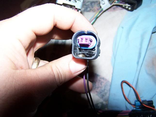
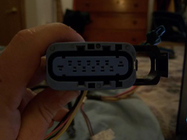
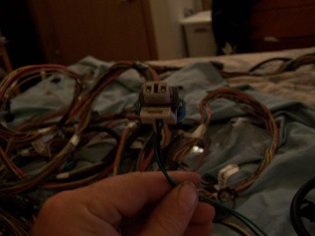
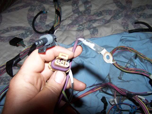
Here are the connectors I can not identify
#1
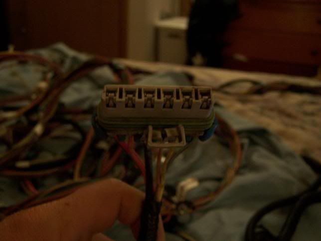
#2
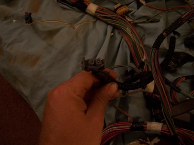
#3
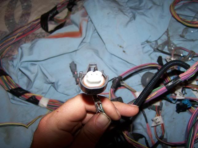
#4
#5 (edit: pin 55 on green connectors says for a/c)
#6
#7
#8
#9 (I assume these are for the alternator, right?)
Thanks to any who can help this fool who thinks he can do his own harness
https://ls1tech.com/forums/conversio...-diagrams.html
First problem is I have nine connectors that I can not seem to match up with what color wires are going to them, second is it seems very little wiring to the tranny is correct, many colors do not match up.
The things I have not matched up yet is the
1. TAC module (thought that was for dbw only and it is showing up on a van?)
2. Accelerator petal position sensor
3. Park/neutral position switch
4. Knock sensors
5. Oil level switch (for oil pan)
Here are the connectors I can not identify
#1
#2
#3
#4
#5 (edit: pin 55 on green connectors says for a/c)
#6
#7
#8
#9 (I assume these are for the alternator, right?)
Thanks to any who can help this fool who thinks he can do his own harness
Last edited by billsnogo; Jul 6, 2010 at 12:58 AM.
u know...since it out...it's prob quicker if u take an ohm meter...set it to buzz when theres a short...and put one lead on one of the pin on the socket and put the other lead up and down the pcm connector to see where it shows up...i did this on my harness making sure there wasn't an open or a short on my stock harness...but it didn't occur to me to label the plugs...
just off the top of my head...i may be wrong...
#8 looks like it goes in the back of the intake manifold for the oil sensor...
#9 since its next to the purple wire that goes to the starter solenoid...i would say goes to that sensor next to the starter...dunnoe wat that sensor is...but its on the motor behind the starter...if u have tiny hands u can get it in there...if not u need to take off the starter to get to that sensor...
my alternator plug if i recalled only had 1 wire off of it...and i think it was for some kind of dummy light...
This thread shows every required connector for a DBC system
http://www.thirdgen.org/techboard/lt...erchanges.html
2) Alt
4) ABS, large hand lock give it away
6) P/Neutral on trans
7) AC compressor clutch
8) AC pressure switch on rear of compressor
9) Oil level (brn/blk) Crank Pos sensor (Yel, Blue, Grn), starter sol ppl
Rest can be removed along with some of the above
This thread shows every required connector for a DBC system
http://www.thirdgen.org/techboard/lt...erchanges.html
Rest can be removed along with some of the above
http://www.thirdgen.org/techboard/lt...erchanges.html
Rest can be removed along with some of the above
thanks for the help so far

All the connectors needed to run. Stand alone includes a fuseblock which isnt posted, but PNs and instructions are on LT1swap.com
How to build the harness is also in that forum under the LS1 swap sticky up top
How to build the harness is also in that forum under the LS1 swap sticky up top
Thank you guys, this is helping.
Couple more questions
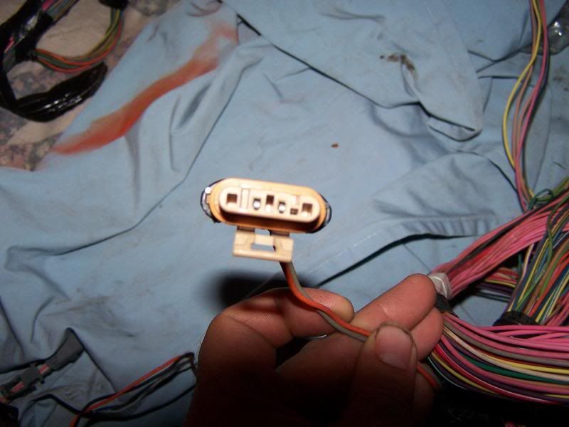
1. Why are there four wires removed from one of the tranny connectors? I thought all would be needed.
2. I am in the process of removing wires from the under hood fuse block (connector c2). According to http://www.lt1swap.com/2000harness.htm to cut all wires except pink. What are you supposed to do with all the pink wires once you find out what connector they go to?
Couple more questions
1. Why are there four wires removed from one of the tranny connectors? I thought all would be needed.
2. I am in the process of removing wires from the under hood fuse block (connector c2). According to http://www.lt1swap.com/2000harness.htm to cut all wires except pink. What are you supposed to do with all the pink wires once you find out what connector they go to?
Trending Topics
LS1 Tech Stories
The Best V8 Stories One Small Block at Time

Topdon ONE vs. Artidiag 800 BT2: Which is the Diagnostic Tablet For You?
Pouria Savadkouei
Gas Monkey Built a 6-Wheel Ferrari Testarossa With a Corvette LT4 Engine
Verdad Gallardo
7 Most Reliable High-Performance Engines GM Has Ever Built
Verdad Gallardo
Amazing '71 Camaro Restomod Is Modern Muscle Car Under the Skin
Verdad Gallardo
6 Common C5 Corvette Failures and What's Involved In Repairing Them
Pouria Savadkouei
Retro Modern Bandit Pontiac Trans AM Comes With Burt Reynolds' Autograph
Verdad Gallardo
Top 10 Greatest Cadillac V Series Performance Models Ever, Ranked
Pouria Savadkouei
Top 10 Most Powerful Chevy Trucks Ever Made!

Hennessey's New Supercharged Silverado ZR2 Has 700 HP
Verdad Gallardo So I am removing all these from the C2 fusebox just to add them to another fuseblock? The one they show with the relay on that site would not have even close to enough spaces to use with all these pink and red/white (my pcm power is not orange, they are red/white).
The tranny connector is #4 up above, or as was said is ABS, but when I trace the wires from the pcm connector, it runs up to this connector and is listed as
32 BLK/WHT 771 Transmission Range Switch Signal A (A/T)
34 WHT 776 Transmission Range Switch Signal P (A/T)
72 YEL 772 Transmission Range Switch Signal B (A/T)
62 GRY 773 Transmission Range Switch Signal C (A/T)
And then I had a light green and dark green wire that was removed from the c2 underhood fuse block, so now it is six wires so far that I have disconnected.
Or does the ABS use signals from the transmission and that is what these are? I do not know how abs determines how to activate, so that may be part of my problem
thanks again guys
Oh, and now for a real dumb question. Why re-pin the connectors? I have been reading on my searches that people want to re-pin all the time. I can understand to do it to add electric fans, but other than that why do it?
The external P/Neutral switch wiring can be deleted in its entirety. B32/B34 need to be grounded when the car is in P/Neutral, beyond that the PCM/trans doesnt care. The remaining 4L60E wiring must stay if you are using an electronic trans but it is contained within the large round trans connector
Not sure about their purpose to the ABS, I just know they dont do anything for the PCM that hinders function
I repin the PCM connectors only. This is done for speed, simplicity and minimal wiring. It's actually the #1 thing I do to harness before disassembly. To move the PCM away from its factory location nearly all the wires must be lengthened/trimmed and its 10x easier to do this with the wires pulled apart. It speeds deleting unneeded wires too because after disassembly, to delete a function one only needs to not reinstall it. Any other connector is depinned for wire repair only
Just wanted to post something I had found while researching my swap regarding the PN transmission range switch. Because of reading this I left mine in my harness. I am not sure how correct it is but thought I would share and let you guys agree/disagree?
Re: What is the PNP (Park/Neutral Position) switch needed for?
________________________________________
The PCM uses the signal to adjust idle speed based on whether the car is in gear or in park/neutral.
As soon as the PCM "sees" the car go in gear it drops the idle speed by around 100 rpm to prevent jerking going into gear, and to prevent tugging at the torque converter.
It can be considered as optional on a swap. As long as the line is left open the PCM will always assume the car is in gear, and will drop to lower rpm when the engine is started. This also causes a much quicker rpm rampdown on a cold engine start.
Some aftermarket wiring harness companies that have no clue as to how the PCM works will wire this line to ground which makes the PCM think the car is always in park or neutral. On some applications this allows some diagnostic tests to be skipped (EGR, purge, etc.) so that these items can be left off without setting a code. The problem is that the idle is too fast then, and the car wantts to pull a little when sitting still, as well as other issues.
Great info guys 
Pocket, how do you get the pins out of the pcm connector? The only way I have been able to do it is cut the wire and push it through, because if I try to pull out the pin, even lifting the white platic tab will not allow me to pull it out un-cut?
Pocket, how do you get the pins out of the pcm connector? The only way I have been able to do it is cut the wire and push it through, because if I try to pull out the pin, even lifting the white platic tab will not allow me to pull it out un-cut?
Pull the white finger back slightly then push the terminal back out the rear. You have to tilt it away from its backrest slightly when you do it. Once you get one free youll smack yourself at how simple it really is
Dang it, I could have saved many wires with the pins if I had known that
Oh well, I save a hand full that still have them.
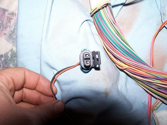
So far I have made good progress, but ran into this connector that has a large red/black wire going to it that runs to connector on pic #6. Where does this plug into?
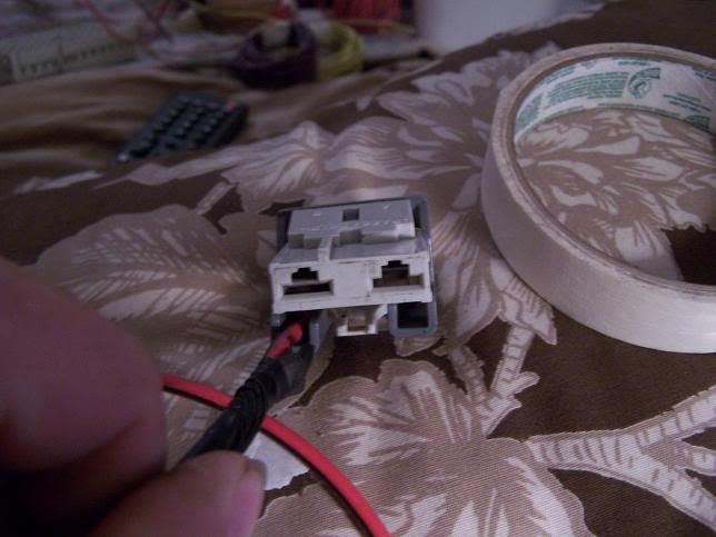
I could not find the colors to the connector on the pin out wiring schematics.
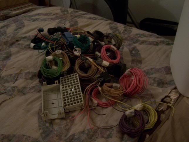
I have removed plenty of wiring though and feel like some progress is being made
Oh well, I save a hand full that still have them.
So far I have made good progress, but ran into this connector that has a large red/black wire going to it that runs to connector on pic #6. Where does this plug into?
I could not find the colors to the connector on the pin out wiring schematics.
I have removed plenty of wiring though and feel like some progress is being made
No idea
Only large wires in the harness are relay related, so start there
For more PCM terminals with wire go to any junkyard. 98+ FWD V6's, LT1s and vortec trucks use the same terminals for their PCMs. Cut the PCM connectors off a wasted car and save some time
Only large wires in the harness are relay related, so start there
For more PCM terminals with wire go to any junkyard. 98+ FWD V6's, LT1s and vortec trucks use the same terminals for their PCMs. Cut the PCM connectors off a wasted car and save some time
Thanks again, now I have another question. According to lt1swap info, on my green pcm connector, pin 10 should be a white wire for tach signal. I have no wire there, and can not find a discription for the 2004 van wiring schematic that says which pin for engine speed signal, do I just add a new wire in pin 10 and have the programmer handle it?
Man, you guys are great
edit: It says to cut all wires from c100, but what about c101? After I removed all the wires that seem to be unneeded that c101 is completely removed also. Just making sure I did not screw up yet.
edit again: ignore post #14 as I eliminated that connector after completely removing c100, now I am guessing I need to add a wire for the tach since there was no wire there.
Last edited by billsnogo; Jul 6, 2010 at 03:15 AM.
Okay, another question. Is there a way have the "gen" light come on for when the alternator dies? There are two wires for my alternator and not sure how I could wire that.
thanks again
thanks again
Run your volt gauge off any IGN wire in the car. If the alt dies you will be running on battery power which will put a substantial drain on the reserve and the overall system voltage will drop noticeably. Alt will charge around 14v, battery backup will run 9-10v