

'70 Nova LY6/TH400 6.0VVT


Its great to have you back! I have like 35 threads I am subscribed to and this one and Frojoes are the only ones having updates. It seems everyone else has either been eaten by zombies or are just so busy there is no time for any updates. Thats awesome the wife ordered your cam and such! Did she go off of the advice from Texas Speed? They seem to turn out some great combos so you should be safe. Keep the updates a coming as I am bored out of my mind right now.

dang man, she's a keeper! that seems like quite a cam -- mid 220s and .620" lift. I see TSP made a sizable power increase with their vvt-3 cam, so I'm interested to see how this bad boy stacks up. Especially since I found a brand-spanking-new LY6 for a very reasonable chunk of change (so much for selling that goat...). 

Thread Starter

Joined: Apr 2010
Posts: 2,816
Likes: 86
From: Instagram @chevyhotrodder
dang man, she's a keeper! that seems like quite a cam -- mid 220s and .620" lift. I see TSP made a sizable power increase with their vvt-3 cam, so I'm interested to see how this bad boy stacks up. Especially since I found a brand-spanking-new LY6 for a very reasonable chunk of change (so much for selling that goat...).
Thread Starter
Joined: Apr 2010
Posts: 2,816
Likes: 86
From: Instagram @chevyhotrodder
As I'm still figuring out the AC, I decided to start the passenger side frame notch for the alternator.


This notch is 3-1/2" deep from the front face of the crossmember and even with the top of the access hole for the LCA bolt. It has a 3-1/2" radius, which helps to maintain some frame height at the thinnest section and should follow the contour of the alternator fairly well. As you can see, part of the LCA perch is in this space. I will leave it intact and trim the new metal around it.
Below I made a paper template for boxing it back in and laid the radiused piece in for pictures to show what the notch will look like. You can see this will tie the top and bottom of the frame together and leave room around the LCA bolt for tool access.


I transfered the template over to a piece of 1/8" plate and cut it out using a die grinder. I made it sligthly oversize and then took my time carefully grinding away material to get a good edge fitup. Fit is very important for welding and I should get a very strong weld from this joint.


If you look closely at the pictures you can see I left two small teeth/tabs at the top edge of the plate. This helps to keep it in place for fit-up and before tacking to get the proper spacing for an open corner weld.
Next I have some welding to do - just have to find the time...
This notch is 3-1/2" deep from the front face of the crossmember and even with the top of the access hole for the LCA bolt. It has a 3-1/2" radius, which helps to maintain some frame height at the thinnest section and should follow the contour of the alternator fairly well. As you can see, part of the LCA perch is in this space. I will leave it intact and trim the new metal around it.
Below I made a paper template for boxing it back in and laid the radiused piece in for pictures to show what the notch will look like. You can see this will tie the top and bottom of the frame together and leave room around the LCA bolt for tool access.
I transfered the template over to a piece of 1/8" plate and cut it out using a die grinder. I made it sligthly oversize and then took my time carefully grinding away material to get a good edge fitup. Fit is very important for welding and I should get a very strong weld from this joint.
If you look closely at the pictures you can see I left two small teeth/tabs at the top edge of the plate. This helps to keep it in place for fit-up and before tacking to get the proper spacing for an open corner weld.
Next I have some welding to do - just have to find the time...
Glad to see your making progress. The notch is looking good. I am guessing without going back over your thread that the mounts, adapters, oil pan clearance, evaporator, headers, and such all fit well now? I hope so, you surely have had a time with all of that. Best of luck to you, keep the pics coming.
Thread Starter
Joined: Apr 2010
Posts: 2,816
Likes: 86
From: Instagram @chevyhotrodder
Time to do some welding!
First, I started with a practice piece with the same fit and orientation as the real weld.

I thought that turned out really good so I went ahead and tacked my piece in...
And welded it up

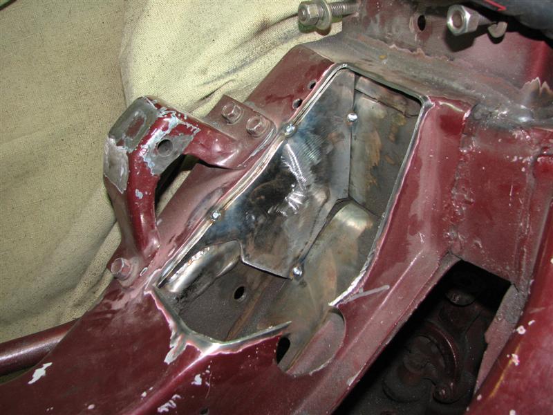
I was very happy with the outside corner weld along the top edge. I went with a full open fitup (no overlap of the metals) and set the welder up for a thinner metal to prevent burn through. I got penetration through to the back and just the right amount of filler for a nice outside radius. (4/50 0.030 C25 MM180)

I then turned up the heat and speed a bit for this standard T joint fillet (4.5/55). I should have turned up the heat and speed a bit on this weld, but it turned out pretty good. It seems like I have a really bad habbit of starting and ending welds away from the ends. I couldn't weld the corner here between the 45 and vertical face because there are lapped pieces of the OEM internal frame structure and I didn't trim my piece right to go between them. There is a piece behind this that I was trimming to, but after measuring again I realized the part had to move forward a little, creating the gap in the corner.

Then there is this booger weld below. I went vertical up on this and was having a very hard time holding the gun and seeing what I was doing. It looks like there's plenty of space to work in the pictures but there isn't. The weld looks cold. I was using the same settings as the previous weld above.

Overall I'm happy with this first round of welding. Next I will need to fit the radiussed bottom/side plate.
First, I started with a practice piece with the same fit and orientation as the real weld.
I thought that turned out really good so I went ahead and tacked my piece in...
And welded it up
I was very happy with the outside corner weld along the top edge. I went with a full open fitup (no overlap of the metals) and set the welder up for a thinner metal to prevent burn through. I got penetration through to the back and just the right amount of filler for a nice outside radius. (4/50 0.030 C25 MM180)
I then turned up the heat and speed a bit for this standard T joint fillet (4.5/55). I should have turned up the heat and speed a bit on this weld, but it turned out pretty good. It seems like I have a really bad habbit of starting and ending welds away from the ends. I couldn't weld the corner here between the 45 and vertical face because there are lapped pieces of the OEM internal frame structure and I didn't trim my piece right to go between them. There is a piece behind this that I was trimming to, but after measuring again I realized the part had to move forward a little, creating the gap in the corner.
Then there is this booger weld below. I went vertical up on this and was having a very hard time holding the gun and seeing what I was doing. It looks like there's plenty of space to work in the pictures but there isn't. The weld looks cold. I was using the same settings as the previous weld above.
Overall I'm happy with this first round of welding. Next I will need to fit the radiussed bottom/side plate.

Thread Starter
Joined: Apr 2010
Posts: 2,816
Likes: 86
From: Instagram @chevyhotrodder
Do you have better luck welding a vertical from the bottom up? I have a Hobart 175 .025" 75/25% and have better luck from top to bottom. I am prolly not using proper technique but it works for me. Most of your welds look good and should be more than adequate in strength. Your moving right along now.
Yes I am!!! But am waiting for my stroker to be completed. I got a call yesterday and its heading to the machine shop. Hopefully in 3-4 weeks it will be ready to be picked up.
Are you enjoying driving yours or has winter weather stuck it in the garage?
Thread Starter
Joined: Apr 2010
Posts: 2,816
Likes: 86
From: Instagram @chevyhotrodder
Do you have better luck welding a vertical from the bottom up? I have a Hobart 175 .025" 75/25% and have better luck from top to bottom. I am prolly not using proper technique but it works for me. Most of your welds look good and should be more than adequate in strength. Your moving right along now.
I did this vertical up and it's a lot tougher to get a pretty weld, but it also makes for a stronger weld because the contaminates "sag" out of the way of the weld puddle. I need to practice a lot more. I would have done vertical down, but I would have had no chance at seeing the leading edge of the weld puddle. Without being able to see, I may have drifted away from the joint, which I have had problems with sometimes when welding in akward places. Before I do the passenger side, I will spend some time practicing and getting tips from other welders.
If you get a tall enough tunnel ram intake you can mount the compressor between its legs!!!??? what ya think?
Thread Starter
Joined: Apr 2010
Posts: 2,816
Likes: 86
From: Instagram @chevyhotrodder
Tweeco makes a gun like that I think. I've never used one.
As for the ac, I think I'll just convert one of the cylinders for refrigerant. A 7 cylinder LSX pumping arctic cold ac would be awesome.
As for the ac, I think I'll just convert one of the cylinders for refrigerant. A 7 cylinder LSX pumping arctic cold ac would be awesome.
10 Second Club


Joined: Aug 2010
Posts: 4,460
Likes: 190
From: Harford Co. Maryland
Problem is going vertical (don't weld downhill) as the heat gets to the metal you sometimes have to cut the heat some.
Can be tough welding without a backer on thinner steel.
Your weld looks decent, but on your vertical it looks like you may have had wire speed high and/or heat low ?
The more you do it ... the better you'll get.
Can be tough welding without a backer on thinner steel.
Your weld looks decent, but on your vertical it looks like you may have had wire speed high and/or heat low ?
The more you do it ... the better you'll get.
Thread Starter
Joined: Apr 2010
Posts: 2,816
Likes: 86
From: Instagram @chevyhotrodder
New plan.


This is a Denso 10S17 compressor which is what originally would have come on this engine. I did some trimming on the OEM compressor bracket which came with my engine in order to graft it around the Doug's adapter and Energy Suspension mount. The compressor is in the OEM position and would run off a rear dedicated belt. The back of the compressor is very close to the motor mount. Frame trimming will be... interesting as will bolt access, but I think I can make it work (heard that before?). Stay tuned.
This is a Denso 10S17 compressor which is what originally would have come on this engine. I did some trimming on the OEM compressor bracket which came with my engine in order to graft it around the Doug's adapter and Energy Suspension mount. The compressor is in the OEM position and would run off a rear dedicated belt. The back of the compressor is very close to the motor mount. Frame trimming will be... interesting as will bolt access, but I think I can make it work (heard that before?). Stay tuned.
Lol!!! You and that damn A/C compressor!! Just yanking your chain, hope this works out for ya for sure. Just a question though, looking at your other accessories, how are you going to run the belt for those? It looks as if you will need an idler on the left head to make it happen. Just wondering as I like the low mount alernator!!! Now to get your butt out there for a trial fit!!! Today????