

5.3L/T56 into 70 Chevelle
 07-01-2011, 09:53 PM
#81
Staging Lane
Thread Starter

Join Date: Feb 2010
Location: Dallas, TX
Posts: 80
Likes: 0
Received 0 Likes
on
0 Posts

ACESHIGH: That speedway motors link is the exact radiator I purchased. I like it because it eliminated the long upper radiator hose (factory truck upper hose). I was having a problem keeping coolant in that giant hose but I had no problems keeping my car cool.
I had a griffin radiator before this AFCO one. I had it for years and didn't have any problems until it started seeping through the fins. When I swapped the LS motor it would gurgle and bubble. It was rather strange. I bought it for $200 or so and figured this time I'd spend to get the right fit.
I had a griffin radiator before this AFCO one. I had it for years and didn't have any problems until it started seeping through the fins. When I swapped the LS motor it would gurgle and bubble. It was rather strange. I bought it for $200 or so and figured this time I'd spend to get the right fit.
 07-01-2011, 11:46 PM
#82
Staging Lane
Thread Starter
Join Date: Feb 2010
Location: Dallas, TX
Posts: 80
Likes: 0
Received 0 Likes
on
0 Posts
Ok, I've been super busy with college and homework as well as work and life. Or at least trying to have one. I've failed to update this as often as I should.
Recently I installed a Vintage Air Sure-Fit kit on the Chevelle. While I had the dash off I wanted to do some clean up and organization of the factory wiring. As i've mentioned before I like to make things easy to remove if every I need to service or repair something.
I started with my dash and the wiring of the new Autometer gauges. To mount the gauges in a 70-72 Chevelle with SS dash you only have a few options. Both involve cutting up your dash and buying premade pieces. Then you screw them into you dash and hope that it doesn't look like a race car. I wanted my gauges to look like they belonged there from the factory.
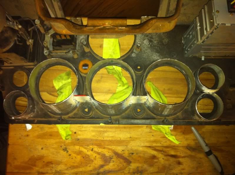
I took the factory plastic gauge bezel and used it as a template.
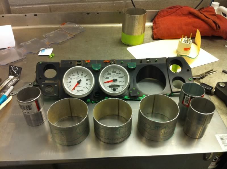
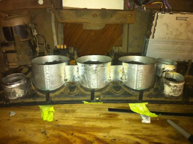
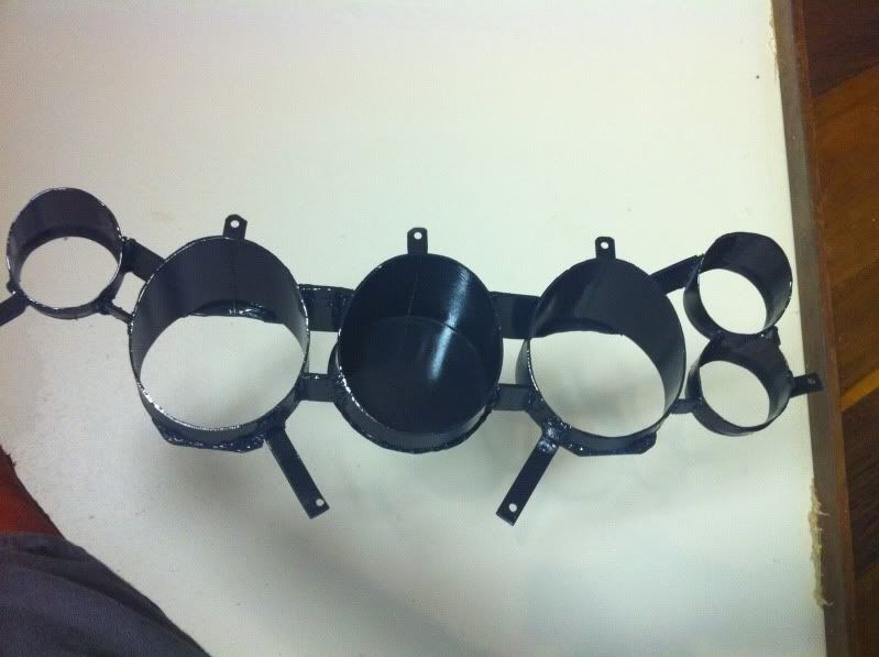
I then took 4" pipe and cut sections to length. I also used a few exhaust transition 2 1/4" for the small gauges. With a bench grinder I beveled them to mimic the factory bezel.
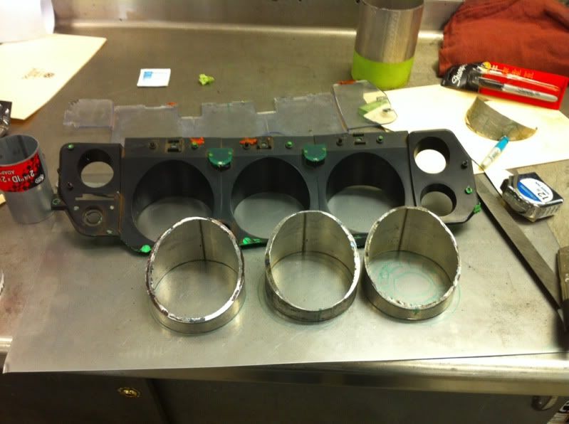
I mocked all the pieces up and started welding them together. I wanted something that contained all the gauges for easy removal and wiring.
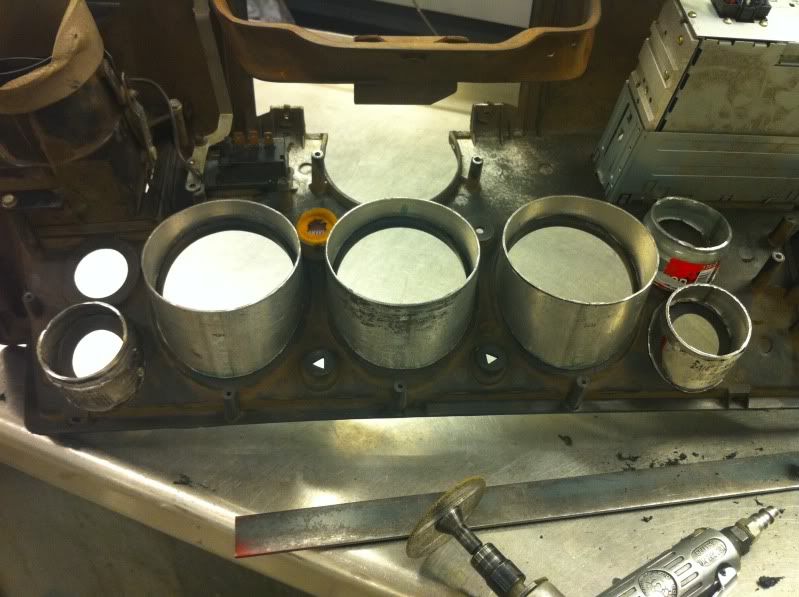
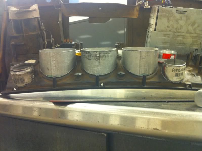
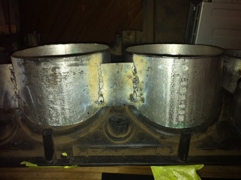
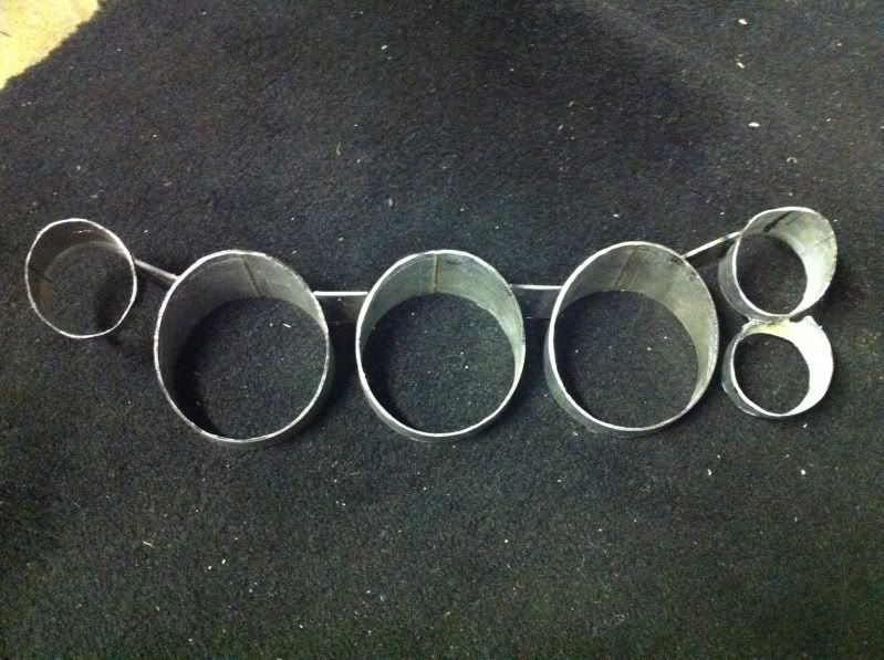
Welded some mounting tabs to screw into the factory holes in the back of the dash. Also welded a blank plate for the center gauge. Unfortunately Autometer doesn't make a 3 3/8" clock in the Ultra-Lite II series.
FYI: had I bought Ultra-Lite I instead there's a company that will make a 3 3/8" clock to match.
With gauges installed
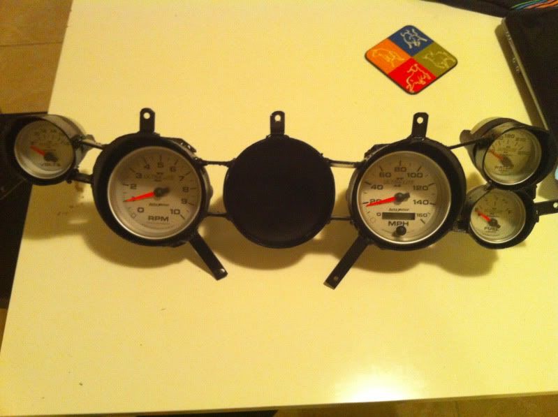
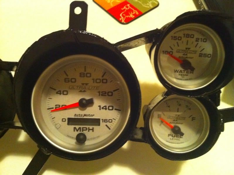
Mounting them was easy using the factory screw locations and screws. Now to start the wiring.
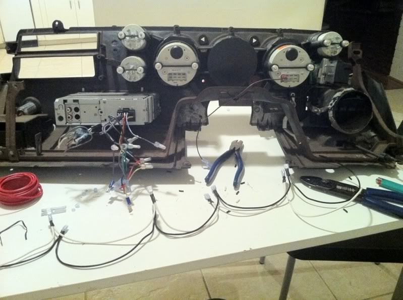
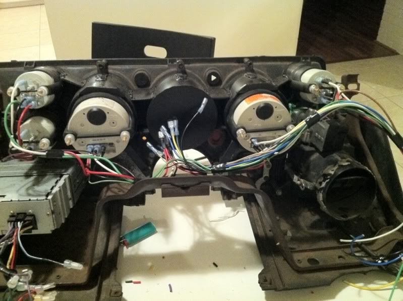
And all done
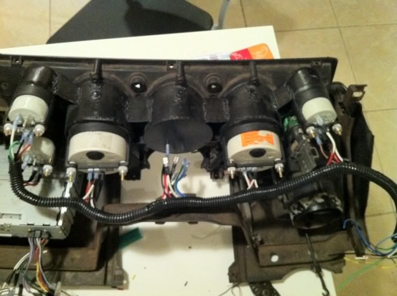
Every gauge has 12V, Ground, Lamp and signal wires. The wires in the center are for Check Engine, Brake, High Beam, turn signals, and 12V/Ground for the future Boost gauge I'll be mounting there.
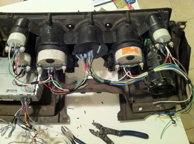
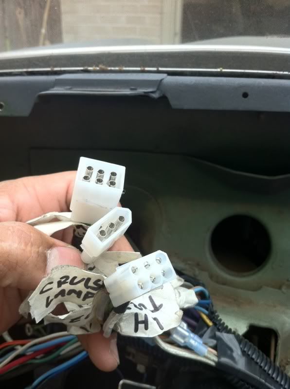
Now for the connectors. Obviously we don't need expensive waterproof connectors on the interior. I found some affordable electrical connectors at Fry's Electronics (www.frys.com) that are available in multiple pin counts of 1,2,3,4,6,8, and 12. They are male/female connectors as well as male/female pins so you could make connectors that cannot be mistakenly plugged in to each other.
I marked all my factory circuits before pinning and color coded my gauge wiring to match.
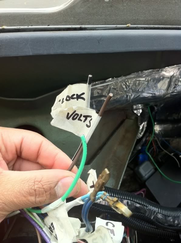
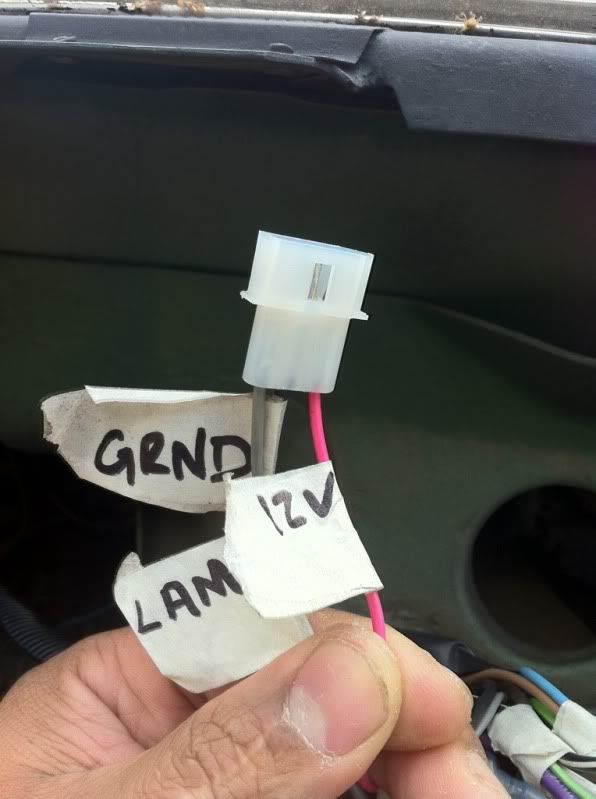
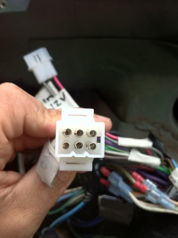
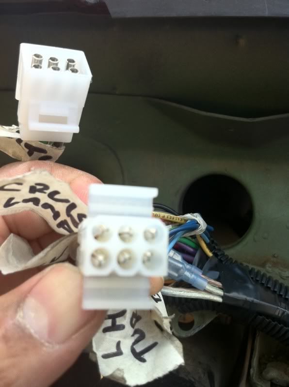
I separated the six gauge signal wires from the indicator light wires and made them different 6-pin connectors. one male and one female so there's no confusion. I also separated the 12V, Ground, and Lamp wires onto a 3-pin connector. If there's any trouble shooting later this will make it easy to chase down.
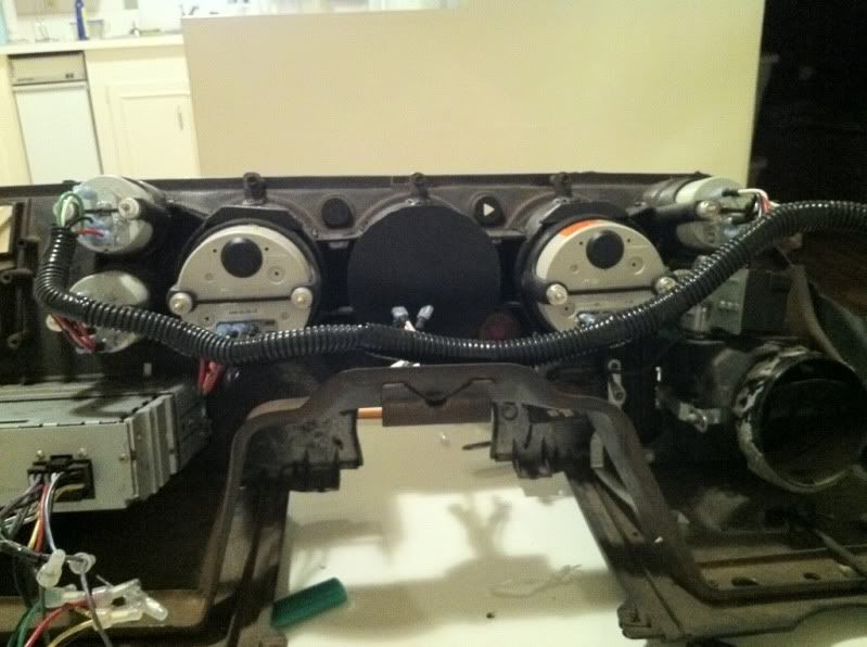
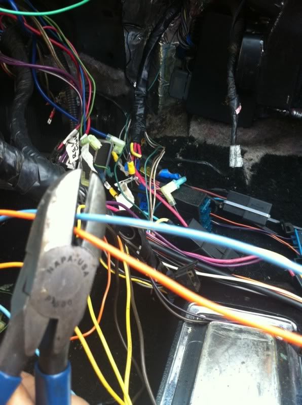
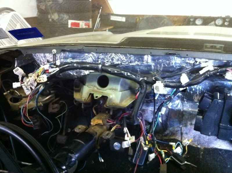
This was my wiring before with the dash out...
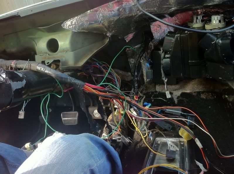
The famous conundrum: which color wire to cut
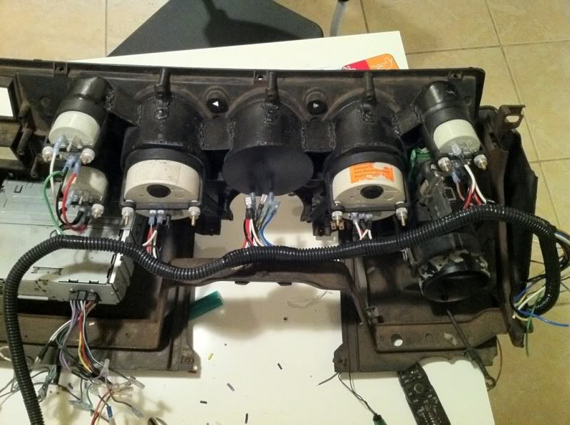
All the wiring after clean up. Everything is loomed, secured up and all the connectors are easily reached once you pull the dash pad. Instead of pulling pins one by one you just disconnect all the connectors, hit the 8-10 bolts that hold the dash in and out it comes. There's connectors for A/C, under dash courtesy lamp, power seats, and Radio (which includes all speakers, 12V, Keyed 12V, ground and lamp all in one).
I like the Radio connector this way because you can swap radios and just add the 12-pin connector to whatever comes with the Radio rather than hard wiring, crimping, or butt-connecting it to your dash harness.
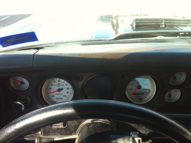
And with the dash in, the view from the drivers seat. (crappy photo but you get the idea)
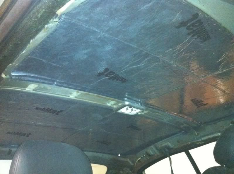
I also took this time to HushMat the roof.
Recently I installed a Vintage Air Sure-Fit kit on the Chevelle. While I had the dash off I wanted to do some clean up and organization of the factory wiring. As i've mentioned before I like to make things easy to remove if every I need to service or repair something.
I started with my dash and the wiring of the new Autometer gauges. To mount the gauges in a 70-72 Chevelle with SS dash you only have a few options. Both involve cutting up your dash and buying premade pieces. Then you screw them into you dash and hope that it doesn't look like a race car. I wanted my gauges to look like they belonged there from the factory.
I took the factory plastic gauge bezel and used it as a template.
I then took 4" pipe and cut sections to length. I also used a few exhaust transition 2 1/4" for the small gauges. With a bench grinder I beveled them to mimic the factory bezel.
I mocked all the pieces up and started welding them together. I wanted something that contained all the gauges for easy removal and wiring.
Welded some mounting tabs to screw into the factory holes in the back of the dash. Also welded a blank plate for the center gauge. Unfortunately Autometer doesn't make a 3 3/8" clock in the Ultra-Lite II series.
FYI: had I bought Ultra-Lite I instead there's a company that will make a 3 3/8" clock to match.
With gauges installed
Mounting them was easy using the factory screw locations and screws. Now to start the wiring.
And all done
Every gauge has 12V, Ground, Lamp and signal wires. The wires in the center are for Check Engine, Brake, High Beam, turn signals, and 12V/Ground for the future Boost gauge I'll be mounting there.
Now for the connectors. Obviously we don't need expensive waterproof connectors on the interior. I found some affordable electrical connectors at Fry's Electronics (www.frys.com) that are available in multiple pin counts of 1,2,3,4,6,8, and 12. They are male/female connectors as well as male/female pins so you could make connectors that cannot be mistakenly plugged in to each other.
I marked all my factory circuits before pinning and color coded my gauge wiring to match.
I separated the six gauge signal wires from the indicator light wires and made them different 6-pin connectors. one male and one female so there's no confusion. I also separated the 12V, Ground, and Lamp wires onto a 3-pin connector. If there's any trouble shooting later this will make it easy to chase down.
This was my wiring before with the dash out...
The famous conundrum: which color wire to cut
All the wiring after clean up. Everything is loomed, secured up and all the connectors are easily reached once you pull the dash pad. Instead of pulling pins one by one you just disconnect all the connectors, hit the 8-10 bolts that hold the dash in and out it comes. There's connectors for A/C, under dash courtesy lamp, power seats, and Radio (which includes all speakers, 12V, Keyed 12V, ground and lamp all in one).
I like the Radio connector this way because you can swap radios and just add the 12-pin connector to whatever comes with the Radio rather than hard wiring, crimping, or butt-connecting it to your dash harness.
And with the dash in, the view from the drivers seat. (crappy photo but you get the idea)
I also took this time to HushMat the roof.
09-06-2011, 07:52 PM
#83
On The Tree

 09-09-2011, 01:35 AM
#84
Staging Lane
Thread Starter
Join Date: Feb 2010
Location: Dallas, TX
Posts: 80
Likes: 0
Received 0 Likes
on
0 Posts
The Autokraft pan was on my list but I didn't want to deal with an oil filter adapter that wasn't built in like factory. I would go with the Autokraft or the RetroLSX. Even the new Holley pan is similar.

 01-04-2013, 12:18 PM
#90
That's what I did, I installed everything where I wanted it then found a place to do the crimping. Several places like napa and the like say they can make hydraulic hoses and etc but when I said I was working on an a/c everyone said they couldn't do it. Had to go to a place that does nothing but make and crimp hoses, which isn't a big deal it was just hard to find. I had no clue what to search for other than 'hose' or 'crimp' or whatever.
Install is a massive pain in the ***, if you are flexible you can get it in without pulling the dash or fender or any of that stuff, but in hindsight I wish I would've at least pulled the fender and thrown in a power radio antennae while in there. But hindsight is 20/20. Either way, the install of the a/c was to date the least fun thing I've done to the car.
Install is a massive pain in the ***, if you are flexible you can get it in without pulling the dash or fender or any of that stuff, but in hindsight I wish I would've at least pulled the fender and thrown in a power radio antennae while in there. But hindsight is 20/20. Either way, the install of the a/c was to date the least fun thing I've done to the car.