

Opinions for my proposed high current wiring
 06-12-2011, 06:05 AM
#1
Teching In
Thread Starter

Join Date: Oct 2010
Posts: 31
Likes: 0
Received 0 Likes
on
0 Posts
I am installing a LS1 in a C3 Corvette. I have proposed the following wiring for the battery/alternator:
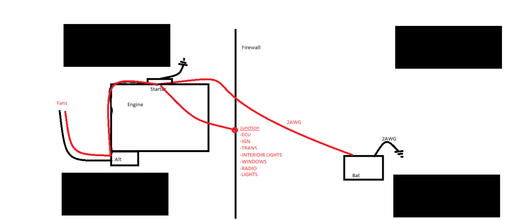
The earth symbol at the starter and the battery is ground to the frame, as per the original setup on the Corvette.
Also did some thread searching and there seems to be some different opinions on how to wire up the two smaller gauge wires that go to the alternator in the connector:
The white wire looks like it goes straight to the battery but where should I connect the other wire (brown)?
 06-12-2011, 11:51 AM
#2

The white wire should not be connected directly to the battery without a 470 ohm 1/2 watt resisitor, you will fry it. The other way to get around connecting it to the battery is to wire it into the red pcm connector #15, no resistor is needed then. The brown wire should be connected to your voltage gauge.
06-13-2011, 07:36 AM
#4
Teching In
Thread Starter
Join Date: Oct 2010
Posts: 31
Likes: 0
Received 0 Likes
on
0 Posts
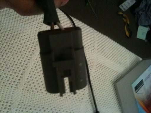
The engine and loom came from a Holden Commodore. So I can see the original connection made to the alternator.
Ok the white wire does go straight to the battery but there looks to be some sort of crimp with heat shrink over it just before it get to the battery. I think this might be the resistor? The brown wire goes to a connector that I think went through the firewall to somewhere.
Can you explain exactly what these wires are doing, both the brown and the white?
06-13-2011, 01:06 PM
#5
If the white wire is going to the battery then its supplying the power the alt needs in order for it to start charging. The brown wire going inside was more than likely linked to the voltage gauge.
06-14-2011, 02:13 AM
#6
 06-14-2011, 02:16 AM
#7
Teching In
Thread Starter
Join Date: Oct 2010
Posts: 31
Likes: 0
Received 0 Likes
on
0 Posts
Ok, but in my car the white wire is going through a resistor straight onto the battery terminal. So there musn't be any control done by the ECU right? So is the brown wire and the high current +ve terminal on the alternator electrically connected?
Can anyone make some comments on how I have proposed to lay the cables out? Does this seem fine?
Can anyone make some comments on how I have proposed to lay the cables out? Does this seem fine?