
59 El Camino LS3 Build
 01-27-2012, 12:34 PM
#21
Teching In

Join Date: Sep 2003
Location: Finland
Posts: 23
Likes: 0
Received 0 Likes
on
0 Posts

Got the pics open today. What a great project "59ElCamino". Really looking forward mine to arive. Lots of similar thoughts what to do. LSx, air-ride, air, brakes... But guess first year will be rust repairing though...
 01-31-2012, 07:58 AM
#22
Teching In
Thread Starter
iTrader: (1)

Join Date: Mar 2011
Location: SE Alabama
Posts: 13
Likes: 0
Received 0 Likes
on
0 Posts
I have been making slow but steady progress. since it is too cold to paint I have decided to work on getting the engine ready to crank. I have the original harness that came with the engine. I inspected the harness and found no damage execpt for a couple scuff marks on the plastic covering. I removed the covering from almost all of the harness and inspected all of the wire for damage. I found a diagram on the internet that had all of engine harness so I tested all of the connctions with a OHM meter and labeled them. I also removed the 6L80 wiring and any wiring not need to run the motor.

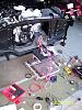
I fitted the harness to the motor by routing the the connectors to the proper locations. Because I changed to a LS3 manifold I had to move things around. Some of the cabling like the O2 sensors were too long. Instead of cutting the wiring I folded it back on it's self and re wraped it. During this process I taped the cables every 5 or 6 inches to keep then organized If I need to reroute I would untape just enough to reroute than tape it up again. It is important to keep you harness organized. In these new motors every sensor, injector and coil has its own wiring that goes back to the computer. So even though there are a lot of wires, every component can be isolated to it's location on the computer and traced bak. This also gives you good insite on what the computer is doing when you program it.


I fitted the harness to the motor by routing the the connectors to the proper locations. Because I changed to a LS3 manifold I had to move things around. Some of the cabling like the O2 sensors were too long. Instead of cutting the wiring I folded it back on it's self and re wraped it. During this process I taped the cables every 5 or 6 inches to keep then organized If I need to reroute I would untape just enough to reroute than tape it up again. It is important to keep you harness organized. In these new motors every sensor, injector and coil has its own wiring that goes back to the computer. So even though there are a lot of wires, every component can be isolated to it's location on the computer and traced bak. This also gives you good insite on what the computer is doing when you program it.
01-31-2012, 08:47 AM
#23
Teching In
Thread Starter
iTrader: (1)
Join Date: Mar 2011
Location: SE Alabama
Posts: 13
Likes: 0
Received 0 Likes
on
0 Posts
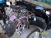
I used the EFI fuse block from Current Performace to integrate the harness with the rest of the car. Their fuse block has the power for the coil packs, injectors, O2 sensors and switched and unswitched voltage for the two ECMs. Also has fan relays and starter relay. It makes the harness look professional and should make it easier to trouble shoot later on. I took most of a day to find all the power wires and solder and heat shrink them. I do not believe I would crimp any connections on the EFI system. Just me. I also had Current Performance build me a harness for the 4L80 trans, TBW, and OBDII connector to finish the harness. I mounted the ECM on the back of the core support and mounted the trans ECM on the fender opposite the motor ECM. The fuse panel is located on the inner fender panel between the two ECMs. The cabling is long enough that you can pull the connectors up and test things if you need too. This is the location is used on the stock Silverado. With the old systems you could hide them under the dash but the new systems have so much wiring to completly hide. So I am trying to hide it in plain sight buy positioning the air cleaner and PS tank.


 01-31-2012, 09:29 AM
#24
Teching In
Thread Starter
iTrader: (1)
Join Date: Mar 2011
Location: SE Alabama
Posts: 13
Likes: 0
Received 0 Likes
on
0 Posts
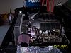
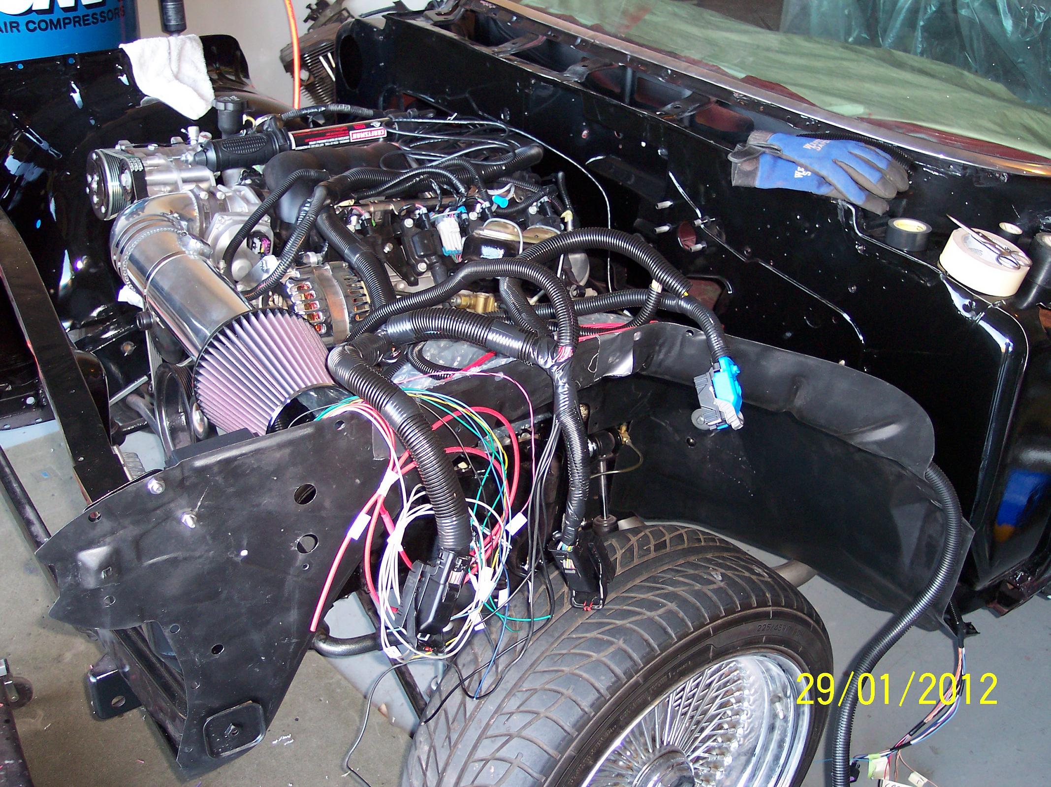
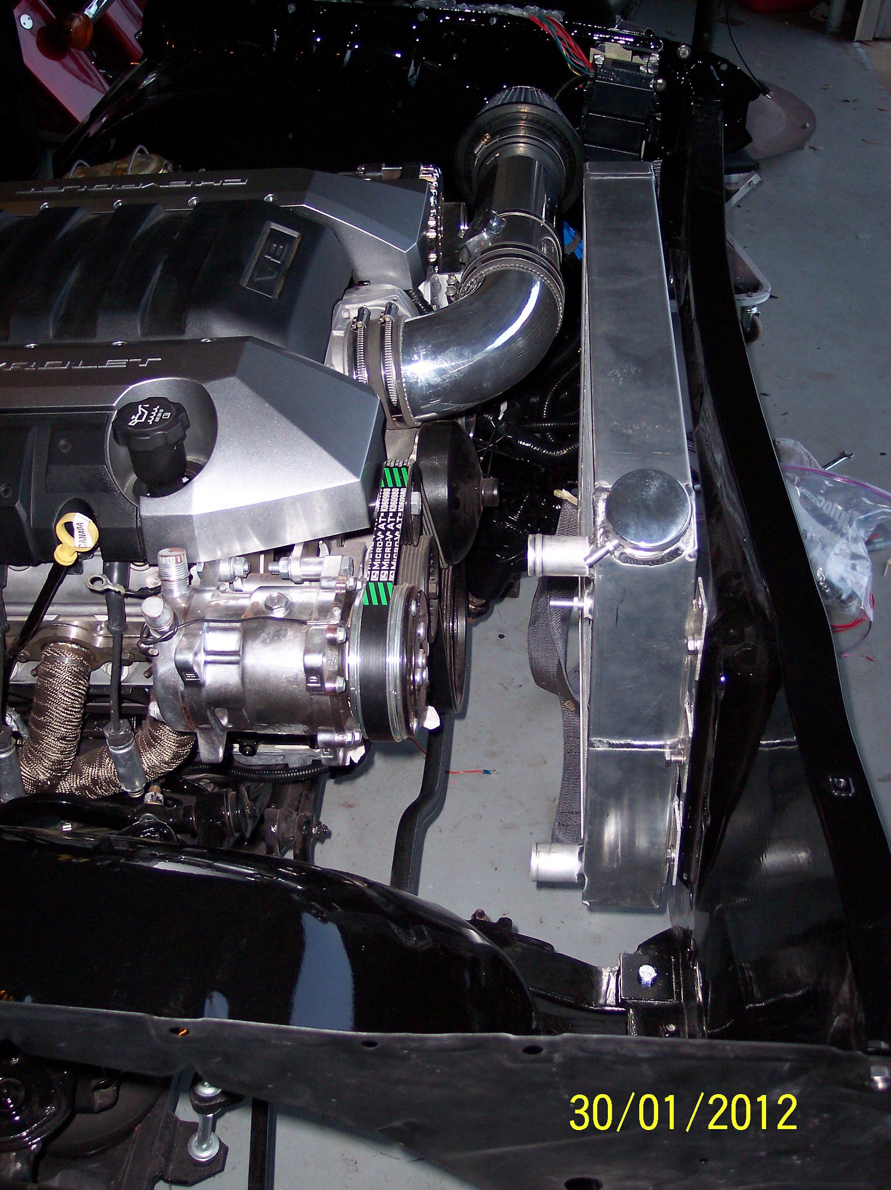
I also worked on the air intake. I used the aluminum tubing because I could weld bungs to it and therfore it is more flexable in the long run. I also like the looks better. I decided to build a bracket to support the tubing because of the length I used. I wanted to get the air clearner away from the motor and take advantage of the vent holes buit into the 59s hood. I also helps to hide the ECMs. I am using the card MAF and mounted it about 10 inches from the TB and 11 inches from the air cleaner. I could not find my instuction when I welded it. I got lucky that it was at least 10 inches from the TB because I did not remember that part. I still need to weld a bung for the PCV connection. I also trimed the camero engine cover and got it on the motor. I helps to dress it up but I will need to extend the back to cover the rest on the engine.
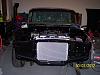
I had to remount the radiator after installing the CPP steering box. I read so much bad stuff on the 605 unit that I broke down and bought the CPP unit. The problem with the CPP unit is that it is longer then the 605 and I had to move the radiator up 1 1/2 inches to clear. They make a notched radiator for a gen 1 engine. I am using a LS syle radiator. It made my hoses line up better but I am real close on the radiator cap. I think I have 1/4-3/8 gap but will not know until I put the hood on. I may have to reposition the radiator cap if it rubs. I hope the new steeing box is worth the trouble.


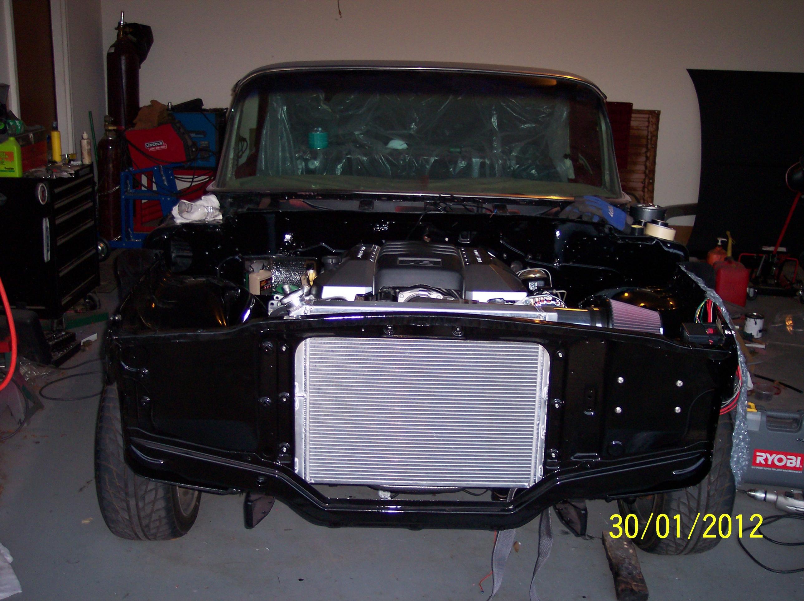
I had to remount the radiator after installing the CPP steering box. I read so much bad stuff on the 605 unit that I broke down and bought the CPP unit. The problem with the CPP unit is that it is longer then the 605 and I had to move the radiator up 1 1/2 inches to clear. They make a notched radiator for a gen 1 engine. I am using a LS syle radiator. It made my hoses line up better but I am real close on the radiator cap. I think I have 1/4-3/8 gap but will not know until I put the hood on. I may have to reposition the radiator cap if it rubs. I hope the new steeing box is worth the trouble.